CN210141867U - Rod body calibration device - Google Patents
Rod body calibration device Download PDFInfo
- Publication number
- CN210141867U CN210141867U CN201921235697.5U CN201921235697U CN210141867U CN 210141867 U CN210141867 U CN 210141867U CN 201921235697 U CN201921235697 U CN 201921235697U CN 210141867 U CN210141867 U CN 210141867U
- Authority
- CN
- China
- Prior art keywords
- rod body
- rod
- plumb bob
- distance
- calibration device
- Prior art date
- Legal status (The legal status is an assumption and is not a legal conclusion. Google has not performed a legal analysis and makes no representation as to the accuracy of the status listed.)
- Active
Links
Images


Abstract
The utility model relates to the field of measuring instrument calibration, in particular to a rod body calibration device, which comprises a measuring mechanism and a supporting mechanism, wherein the supporting mechanism is detachably connected with the top of a rod body, at least one plumb bob mechanism is hung on the supporting mechanism, the measuring mechanism is used for measuring the distance between the plumb bob mechanism and the rod body, so that the distance between any two points on the plumb bob mechanism and the rod body can be measured by the measuring mechanism, the direction of rod body deviation can be judged easily through the difference of the measured distance, and the rod body can be conveniently adjusted to the state that the distance between any two points on the plumb bob mechanism and the distance between the rod body are equal, thereby realizing the plumb calibration of the rod body, the calibration mode is simpler, the calibration device has simple structure, easy preparation and convenient operation, the occupied area is smaller when in use, and only one measuring person is needed to complete the calibration of the rod body, manpower, material resources and time consumed in the rod body calibration process are reduced.
Description
Technical Field
The utility model relates to a measuring apparatu proofreading field, in particular to school device is examined to the body of rod.
Background
The centering rod or the RTK moving rod is widely applied to construction measurement, the rod body needs to be kept vertical in the using process of the centering rod or the RTK moving rod to ensure the measurement precision, whether the rod body is vertical or not is generally determined through judging the position of the circular level bubble on the rod body, but due to the influence of factors such as vibration, carrying, collision and the like, the circular level bubble on the rod body is leveled, but the rod body is still plumb, the precision of a measurement result is directly influenced, and therefore before the construction measurement, the rod body needs to be strictly corrected, so that the rod body is in a plumb state when the level bubble is leveled.
At present, a simple mechanism capable of assisting in rod body calibration of a centering rod or an RTK moving rod does not exist, a traditional calibration method is to use a rod body as a center, two theodolites or total stations are arranged in directions with lines of sight forming 90 degrees with each other, a third measurer is instructed to erect the rod body and adjust a calibration screw of a leveling bubble through observation instruments of the two measurers, the bubble is centered, and the rod body is kept in a completely vertical state after repeated adjustment.
Therefore, there is a need to design a calibration device capable of assisting in calibrating a rod body of a centering rod or an RTK moving rod to overcome the above-mentioned disadvantages.
SUMMERY OF THE UTILITY MODEL
The utility model aims to provide a: aiming at the defects of rod body calibration of the conventional centering rod or TRK moving rod, the rod body calibration device which is small in occupied area, convenient to operate, high in precision, simple in calibration process and low in labor consumption, material resources and time consumption is provided.
In order to realize the purpose, the utility model discloses a technical scheme be:
the utility model provides a school device is examined to body of rod, includes measuring mechanism and supporting mechanism, the supporting mechanism can be dismantled with the body of rod top and be connected, the last at least one plumb bob mechanism that hangs of supporting mechanism, measuring mechanism is used for measuring plumb bob mechanism with distance between the body of rod.
The utility model discloses a school device is examined to the body of rod sets up the structure that supporting mechanism hung plumb bob mechanism through adopting at the body of rod top of waiting to examine the school, makes plumb bob mechanism remains vertical state all the time under self action of gravity, and the rethread measuring mechanism measures the distance between arbitrary two points and the body of rod in plumb bob mechanism, and easier through the difference of surveying the distance, judges the direction of body of rod skew, and then when convenient adjusting the body of rod to the distance between arbitrary two points and the body of rod in plumb bob mechanism equals, realizes the plumb school of examining of the body of rod, it is simpler to examine the school mode, this school device simple structure of examining, the preparation is easy, convenient operation, need not set up with the help of the outside during use, area is less, only need a measuring personnel can accomplish the school of examining of the body of rod, the manpower and materials and the time that the.
Preferably, the plumb bob mechanism comprises a connecting wire and a balancing weight connected with the connecting wire, and the connecting wire is hung on the supporting mechanism. The balancing weight can be easier to maintain the vertical state of the connecting wire through the action of gravity, so that the accuracy of data measured by the measuring mechanism is ensured, meanwhile, the connecting wire and the supporting mechanism are convenient to connect, and the preparation and the use of the calibration device are further convenient.
Preferably, the supporting mechanism comprises a connector and a hanging piece arranged on the connector, the connector is detachably connected with the rod body, and the connecting line is hung on the hanging piece. The installation of suspension part on waiting to examine the school rod body is realized through the connector more convenient, through hang the connecting wire and realize the installation of plumb bob mechanism on the suspension part, further makes things convenient for this use of checking the school device.
Preferably, the hanger is provided with at least one threading hole adapted to the connecting line. The connecting wire can more easily pass realize after the through wires hole with being connected of flying piece, make things convenient for the installation of plumb bob mechanism to be favorable to regarding the distance between through wires hole and the body of rod top central point as the benchmark distance.
Preferably, the hanging piece further comprises a notch penetrating through the edge of the hanging piece, and the notch is communicated with the threading hole. Go into the through wires hole with the connecting wire from the notch card, further make things convenient for the installation of plumb bob mechanism, simultaneously, can adopt the connecting wire of both ends connection balancing weight according to actual conditions, make the connecting wire card go into the body of rod in the different radial ascending threading holes of side, realize the installation of plumb bob mechanism, make plumb bob mechanism structure simpler, it is more convenient to use.
Preferably, the hanging part comprises at least two support plates which are arranged in a coplanar manner, an included angle between every two adjacent support plates is 90 degrees, and each support plate is provided with at least one threading hole. According to the actual situation, when the plumb bob mechanisms are respectively arranged on the two supporting plates which are distributed in the right-angle state, the vertical state of the rod body is measured from different radial directions of the rod body, and then the adjustment and calibration are realized, so that the calibration result is more accurate.
Preferably, a horizontal bubble instrument is arranged on the suspension member. Make the horizontal state of flying piece is judged to the bubble position of accessible horizontal bubble appearance, when flying piece level setting, also can further ensure that the line between through wires hole and the body of rod top central point extends along the flying piece surface for distance between through wires hole and the body of rod top central point is fixed, and the convenience is as the benchmark distance, makes the calibration result more accurate.
Preferably, at least one hook portion is provided on the hanger. Hang plumb bob mechanism through couple portion for plumb bob mechanism's installation is more convenient, makes the connecting wire combination that conveniently adopts the unilateral to connect the balancing weight as plumb bob mechanism, when plumb bob mechanism is a plurality of, makes things convenient for the independent suspension installation respectively of a plurality of plumb bob mechanisms.
Preferably, the leveling device further comprises a correction poking needle, and the correction poking needle is used for adjusting the level bubble on the rod body. The leveling bubble is adjusted by adopting a conventional correction poking needle, so that when the rod body is in a vertical state, the circular bubble of the leveling bubble is positioned on the central axis of the rod body, and the vertical correction of the rod body is completed.
To sum up, owing to adopted above-mentioned technical scheme, the utility model discloses a body of rod is examined school device's beneficial effect is:
1. the structure that the supporting mechanism is arranged at the top of the rod body to be calibrated to hang the plumb bob mechanism is adopted, the distance between any two points on the plumb bob mechanism and the rod body is measured through the measuring mechanism, the offset direction of the rod body is judged easily through the difference of the measured distances, and further the vertical calibration of the rod body is realized when the rod body is conveniently adjusted to the condition that the distance between any two points on the plumb bob mechanism and the distance between the rod bodies are equal, and the calibration mode is simpler;
2. the checking device is simple in structure, easy to prepare and convenient to operate, occupies a small area during use, can finish checking the rod body by only one measuring person, and reduces manpower, material resources and time consumed in the checking process of the rod body.
Drawings
Fig. 1 is a schematic structural view of a rod body calibration device in a use state according to the present invention;
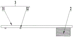
FIG. 2 is a schematic structural view of the support mechanism in embodiment 1;
FIG. 3 is a schematic structural view of the support mechanism in embodiment 2;
FIG. 4 is a schematic structural view of the supporting mechanism in embodiment 3;
FIG. 5 is a schematic structural view of a supporting mechanism for carrying out another effect of embodiment 3;
fig. 6 is a schematic flow chart of a calibration method of the rod calibration device of the present invention.
Reference numerals
1-measuring mechanism, 2-connector, 3-suspension part, 31-supporting plate, 32-hook part, 4-plumb bob mechanism, 41-connecting wire, 42-balancing weight, 5-threading hole, 6-notch, 7-horizontal bubble instrument, 8-correction poking needle, 9-rod body, 91-level bubble and 92-rod body bracket.
Detailed Description
In order to make the objects, technical solutions and advantages of the present invention more clearly understood, the present invention will be further described in detail with reference to the accompanying drawings and specific embodiments. It should be understood that the specific embodiments described herein are for purposes of illustration only and are not intended to limit the invention.
Example 1
As shown in fig. 1-2, a calibration device is examined to body of rod, including measuring mechanism 1 and supporting mechanism, supporting mechanism includes connector 2 and sets up flying piece 3 on the connector 2, connector 2 can be dismantled with the body of rod 9 top and be connected, it has at least one plumb bob mechanism 4 to hang on the flying piece 3, plumb bob mechanism 4 include connecting wire 41 with the balancing weight 42 that connecting wire 41 connects, connecting wire 41 hangs on the flying piece 3, measuring mechanism 1 is used for measuring plumb bob mechanism 4 with distance between the body of rod 9, measuring mechanism 1 is steel tape and/or square.
In the rod body calibration device of the present embodiment, the connector 2 adopted when the prism lens in the prior art is connected with the centering rod is preferably adopted, so that the hanging part 3 is stably connected with the top of the rod body 9 through the connector 2; preferably, a plurality of hook portions 32 for hanging the connection wire 41 of the plumb bob mechanism 4 are provided on the hanger 3; preferably, two connecting wires 41 with one end hanging with a balancing weight 42 are hung on the hook part 32, and two plumb bob mechanisms 4 are arranged on two radial directions of the rod body 9, so that the distance between the connecting wires 41 of the two plumb bob mechanisms 4 and the rod body 9 can be conveniently and respectively measured, the rod body bracket 92 is adjusted in two directions according to the distance difference, when the distance between any two points on the plumb bob mechanisms 4 and the rod body 9 is equal, the rod body 9 is adjusted to be in a vertical state, an adjusting screw under a level bubble 91 seat on the rod body 9 is adjusted through a conventional correcting poking needle 8, the round bubble of the level bubble 91 is positioned on the central axis of the rod body 9, four lines of the connecting wires 41 of the two plumb bob mechanisms 4, the central axis of the rod body 9 and the round bubble of the level bubble 91 in the vertical direction are parallel to each other and are vertical to the vertical plane, the checking and the checking device is simple in operation, the floor area is little, do not need other auxiliary facilities, only need a measurement personnel to measure the perpendicular distance between the selection point of co-altitude and the body of rod 9 the central axis many times on the connecting wire, and adjust body of rod support 92 to the same connecting wire 41 on the multi-point measure the distance homogeneous phase isochronism, can realize the body of rod 9 and examine the school in this connecting wire 41 ascending plumb, through the measurement and the contrast of measuring result to setting up plumb bob mechanism 4 in the equidirectional, realize the body of rod 9 and examine the school completely plumbly, the principle is simple, the operation is convenient, the manpower and materials and the time that the body of rod 9 process of examining the school consumes.
Preferably, a horizontal bubble meter 7 is arranged on the suspension member 3. When the hanger 3 is horizontally arranged, the length of a connecting line between the hook part 32 and the top center of the rod body 9 along the surface of the hanger 3 is the vertical state of the rod body 9, the vertical distance between the connecting line 41 and the central axis of the rod body 9 cannot be changed under the influence of the inclined state of the rod body 9, the distance can be used as a reference distance for judging the offset direction of the rod body 9, when the measured vertical distance between any point on the connecting line 41 and the central axis of the rod body 9 is larger than the reference distance, the rod body 9 is adjusted towards the opposite direction of the connecting line 41, the measured distance is equal to the reference distance, and after vertical and multi-point measurement comparison and adjustment, the calibration of the rod body 9 is realized, and the calibration result is more accurate.
Example 2
As shown in fig. 1 to 3, the rod body calibration device of the present embodiment has the same structure as that of embodiment 1, except that: the hanger 3 comprises at least two support plates 31 arranged in a coplanar manner, an included angle between every two adjacent support plates 31 is 90 degrees, and each support plate 31 is provided with a threading hole 5 matched with the connecting wire 41.
The rod body calibration device of the embodiment preferably adopts a steel plate with the thickness of 3mm and the width of 2.5cm to process and manufacture a suspension part 3 with two support plates 31, the two support plates 31 are mutually distributed in a 90-degree right-angle state on the same plane, a 1mm small hole is drilled on each support plate 31 to serve as a threading hole 5, the distance between the two threading holes 5 and the foot point of the suspension part 3 is equal, the connector 2 is welded at the central bottom of the right-angle intersection of the support plates 31 to manufacture the support mechanism, preferably, the connecting wire 41 passes through the threading holes 5 to be wound, bound and fixed, so as to realize the installation of the plumb bob mechanism 4, the plumb bob mechanism 4 and the support mechanism are conveniently connected, the arrangement of the two plumb bob mechanisms 4 in two mutually perpendicular radial directions of the rod body 9 is relatively easily realized, the calibration of the rod body 9 in the two mutually perpendicular radial directions is realized, and the calibration result is relatively, and manpower, material resources and time consumed in the rod body calibration process are further reduced.
Example 3
As shown in fig. 1 to 5, the rod body calibration device of the present embodiment has the same structure as that of embodiment 2, except that: a plurality of threading holes 5 are equidistantly arranged on a supporting plate 31 of the supporting mechanism, notches 6 penetrating through the side edges of the supporting plate 31 are formed in the width direction of the supporting plate 31, the notches 6 correspond to the threading holes 5 one to one, and distance marks used for marking the distance between the threading holes 5 and foot hanging points of a hanging piece 3 are arranged on the edges of the notches 6.
The rod body checking and calibrating device of the embodiment preferably adopts the plumb bob mechanism 4 formed by connecting the balancing weights 42 at two ends of the connecting wire 41, when the checking and calibrating device is used, the middle position of the connecting wire 41 of the plumb bob mechanism 4 is clamped into the threading holes 5 on the two adjacent supporting plates 31, the arrangement of the plumb bob mechanism 4 on different radial directions of the rod body 9 is realized, and the connecting wire 41 of the plumb bob mechanism 4 and the supporting plates 31 are in a clamping structure, so that the connection of the plumb bob mechanism 4 and the supporting plates 31 can be more conveniently realized, the checking and calibrating device with the structure is more convenient to use, the connecting wire 41 can be adjusted to be matched with different threading holes 5 or a plurality of plumb bob mechanisms 4 are hung on one supporting plate 31 according to actual conditions, the reference point in the checking and calibrating process is increased, and the connecting wire 41 with different vertical distances from the central axis of the rod body 9 conveniently passes through, Diversified distance measurement and contrast, more accurate judgement body of rod 9's vertical state avoids the checking error that measuring error leads to, makes the checking result more accurate.
Example 4
As shown in fig. 1 to 6, the calibration method of the rod calibration device of the present embodiment includes the following steps: step 1: installation and calibration device: erecting a rod body 9, and arranging the calibration device on the rod body 9; step 2: measuring and recording the reference distance: measuring the connecting line distance of the top suspension point of the plumb bob mechanism 4 and the top center of the rod body 9 on the same plane, and recording the connecting line distance as a reference distance; and step 3: measuring and recording comparison distance: measuring the vertical distance from any point on the plumb bob mechanism 4 to the central axis of the rod body 9, and recording the vertical distance as a comparison distance; and 4, step 4: judging the deflection direction of the rod body 9: when the comparison distance is greater than the reference distance, judging that the rod body 9 deviates towards one side of the threading hole 5, and when the comparison distance is less than the reference distance, judging that the rod body 9 deviates towards the side opposite to the threading hole 5; and 5: checking the rod body 9: measuring the reference distance and the comparison distance corresponding to the plumb bob mechanisms 4 arranged on the rod body 9 in different radial directions, and respectively adjusting the rod body 9 according to the judgment result of the step 4 until the comparison distance and the reference distance measured on each plumb bob mechanism 4 are equal, wherein the rod body 9 is in a vertical state; step 6: and (4) overall calibration: after the rod body 9 is in a vertical state, measuring the distance between any two points on the connecting line 41 and the rod body 9 for comparison, and if the comparison result is unequal, deforming the rod body 9 and needing to be replaced or maintained; and 7: adjusting a level bubble: and a correcting poking needle 8 is adopted to adjust a screw below the level bubble 91 on the rod body 9, so that the bubble of the level bubble 91 is positioned on the central axis of the rod body 9, and the calibration is completed.
The rod body checking and calibrating method of the rod body checking and calibrating device of the embodiment adopts the rod body checking and calibrating device which has small occupied area, convenient operation, high precision, simple calibrating process and less consumption of manpower, material resources and time, so that the vertical calibration of the rod body 9 can be completed only by one measuring person, meanwhile, the plumb bob mechanisms 4 are respectively arranged on the different radial directions of the rod body 9, so that the calibration of the rod body 9 is respectively realized on the different radial directions of the rod body 9, the precision of the calibration result is higher, in addition, the top of the rod body 9 to be calibrated is provided with the calibrating device, so that the calibrating process is not influenced by the height of the rod body 9 or the environment, the rod body 9 after the calibration can be ensured to be more accurate in the testing results on different heights or different directions in the using process, and a plurality of plumb bob mechanisms 4 can be arranged on the supporting mechanism on the top of the rod body 9 according to the actual situation, each plumb bob mechanism 4 is arranged in one radial direction of the rod body 9, and when checking, the vertical distance between the connecting line 41 of each plumb bob mechanism 4 and the central axis of the rod body 9 is respectively measured, the vertical distance between each measuring point on the rod body 9 and the connecting line 41 and the vertical distance between the rod bodies 9 are adjusted to be equal, so that the rod bodies 9 are in a vertical state, and then the level bubble 91 is adjusted, thereby realizing the checking and the calibration of the rod bodies 9, and the checking and the calibration method are simple.
The above embodiments are only used to illustrate the present invention and not to limit the technical solutions of the present invention, and although the present invention has been described in detail with reference to the above embodiments, the present invention is not limited to the above embodiments, therefore, any modifications or equivalent replacements of the present invention can be made, and all technical solutions and modifications without departing from the spirit and scope of the present invention should be covered by the claims of the present invention.
Claims (8)
1. The utility model provides a body of rod calibration device which characterized in that: including measuring mechanism and supporting mechanism, the supporting mechanism can be dismantled with the body of rod top and be connected, the last at least one plumb bob mechanism that hangs of supporting mechanism, measuring mechanism is used for measuring plumb bob mechanism with distance between the body of rod.
2. A rod calibration device according to claim 1 wherein: the plumb bob mechanism comprises a connecting line and a balancing weight connected with the connecting line, and the connecting line is hung on the supporting mechanism.
3. A rod calibration device according to claim 2, wherein: the supporting mechanism comprises a connector and a hanging piece arranged on the connector, the connector is detachably connected with the rod body, and the connecting wire is hung on the hanging piece.
4. A rod calibration device according to claim 3 wherein: the hanging piece is provided with at least one threading hole matched with the connecting line.
5. A rod calibration device according to claim 4, wherein: the hanging piece is characterized by further comprising a notch penetrating through the edge of the hanging piece, and the notch is communicated with the threading hole.
6. A rod calibration device according to claim 5, wherein: the hanger comprises at least two support plates which are arranged in a coplanar manner, an included angle between every two adjacent support plates is 90 degrees, and each support plate is provided with at least one threading hole.
7. A rod calibration device according to claim 3 wherein: at least one hook part is arranged on the hanging part.
8. A rod calibration device according to any one of claims 1 to 7 wherein: the leveling device further comprises a correction poking needle, and the correction poking needle is used for adjusting the level bubble on the rod body.
Priority Applications (1)
| Application Number | Priority Date | Filing Date | Title |
|---|---|---|---|
| CN201921235697.5U CN210141867U (en) | 2019-08-01 | 2019-08-01 | Rod body calibration device |
Applications Claiming Priority (1)
| Application Number | Priority Date | Filing Date | Title |
|---|---|---|---|
| CN201921235697.5U CN210141867U (en) | 2019-08-01 | 2019-08-01 | Rod body calibration device |
Publications (1)
| Publication Number | Publication Date |
|---|---|
| CN210141867U true CN210141867U (en) | 2020-03-13 |
Family
ID=69736887
Family Applications (1)
| Application Number | Title | Priority Date | Filing Date |
|---|---|---|---|
| CN201921235697.5U Active CN210141867U (en) | 2019-08-01 | 2019-08-01 | Rod body calibration device |
Country Status (1)
| Country | Link |
|---|---|
| CN (1) | CN210141867U (en) |
Cited By (1)
| Publication number | Priority date | Publication date | Assignee | Title |
|---|---|---|---|---|
| CN110307859A (en) * | 2019-08-01 | 2019-10-08 | 中铁二局集团有限公司 | A kind of body of rod calibration device and its calibration method |
-
2019
- 2019-08-01 CN CN201921235697.5U patent/CN210141867U/en active Active
Cited By (1)
| Publication number | Priority date | Publication date | Assignee | Title |
|---|---|---|---|---|
| CN110307859A (en) * | 2019-08-01 | 2019-10-08 | 中铁二局集团有限公司 | A kind of body of rod calibration device and its calibration method |
Similar Documents
| Publication | Publication Date | Title |
|---|---|---|
| CN202255381U (en) | Level bar | |
| CN206709845U (en) | A kind of forced centering pedestal of levelling | |
| US6137065A (en) | Level weighing device | |
| CN210141867U (en) | Rod body calibration device | |
| CN111121736A (en) | Segment attitude deviation measuring method and device based on any angle | |
| CN108225263B (en) | Elevation vertical transfer device and method for measuring elevation by using same | |
| CN113063399A (en) | Elevation measurement method and system | |
| CN210952737U (en) | Flatness detection device for building construction template | |
| CN207850385U (en) | A kind of marker post for level meter | |
| CN213748402U (en) | Digital display precision measuring instrument for measuring major diameter main cable strand of suspension bridge | |
| CN213579900U (en) | Measurement calibrating device | |
| CN209783546U (en) | Laser arch measuring instrument of large-span template | |
| CN210154503U (en) | Prefabricated component straightness detection device that hangs down | |
| CN209085601U (en) | Inclination measuring device | |
| CN209841025U (en) | Measure measuring device of girder steel levelness, steel column straightness that hangs down | |
| CN220625292U (en) | Self-balancing leveling device | |
| CN208792065U (en) | Orbit measurement rail centralizer | |
| CN112683254A (en) | Verticality measuring device and verticality measuring method | |
| CN207946093U (en) | A kind of prism apparatus for measurement | |
| CN110307859A (en) | A kind of body of rod calibration device and its calibration method | |
| CN215064481U (en) | Building wall body settlement leveling ruler pad | |
| CN107014355A (en) | Detection method and detection means that a kind of tapered stud is spent vertically | |
| CN211576202U (en) | Building engineering straightness measuring device that hangs down | |
| CN213543800U (en) | Positioning device for microphone for indoor noise test | |
| CN111780733B (en) | Method for measuring levelness and verticality of crane beam |
Legal Events
| Date | Code | Title | Description |
|---|---|---|---|
| GR01 | Patent grant | ||
| GR01 | Patent grant |