CN210138609U - Stirring device for processing powdery mullite into paste - Google Patents
Stirring device for processing powdery mullite into paste Download PDFInfo
- Publication number
- CN210138609U CN210138609U CN201920856743.7U CN201920856743U CN210138609U CN 210138609 U CN210138609 U CN 210138609U CN 201920856743 U CN201920856743 U CN 201920856743U CN 210138609 U CN210138609 U CN 210138609U
- Authority
- CN
- China
- Prior art keywords
- stirring
- mullite
- fixedly connected
- wall
- hollow
- Prior art date
- Legal status (The legal status is an assumption and is not a legal conclusion. Google has not performed a legal analysis and makes no representation as to the accuracy of the status listed.)
- Active
Links
Images


Abstract
The utility model discloses a process pulverous mullite into pasty agitating unit of thick liquid, including the agitator tank, the top fixedly connected with driving motor of agitator tank, the first spiral stirring leaf of circumference inner wall fixedly connected with of hollow churn, the water conservancy diversion hole has been seted up on the circumference surface of hollow churn, initiative conical gear's surface toothing has driven conical gear, the surface of stirring horizontal pole is connected with T type puddler through coupling mechanism. The utility model discloses an above-mentioned isotructure's cooperation has solved current agitating unit and has stirred the in-process that changes thick liquid to mullite, is difficult for stirring against the current to the mullite thick liquid, leads to the mullite thick liquid to stir and changes thick liquid thoroughly inadequately easily, produces the influence to the further processing of mullite easily, and then can produce the problem of influence to the density and the heat conductivity of mullite bonding property, high temperature oxidation resistance and mullite.
Description
The technical field is as follows:
the utility model relates to a mullite processing stirring technical field specifically is a processing pulverous mullite into pasty agitating unit of thick liquid.
Background art:
mullite (or mullite, Aluminum silicate) refers to a series of minerals composed of aluminosilicate, mullite is a high-quality refractory material and is a main component of clay bricks, high-alumina bricks, porcelain and the like, the process flow for artificially producing mullite comprises the steps of directly conveying purchased raw materials coal gangue and kaolin into a raw material warehouse, loading the raw materials coal gangue and kaolin into an original ore warehouse by a loader, feeding the raw materials into a jaw crusher for crushing and screening by a groove type feeder, and then carrying out a series of steps of batching, ball milling, slurry pond melting, spray granulation, extrusion molding, drying, sintering, crushing, inspection and warehousing and the like, wherein in the production and processing process of mullite, slurry stirring is an important step, if slurry melting is not complete, the later stage can influence the bonding performance, the high-temperature oxidation resistance and the density and the thermal conductivity of mullite, and because the existing stirring device is used for stirring and slurrying the mullite, the countercurrent stirring of the mullite slurry is not easy, the stirring and slurrying of the mullite slurry are not sufficient and thorough, the further processing of the mullite is easy to be influenced, and further the combination property, the high-temperature oxidation resistance and the density and the heat conductivity of the mullite are influenced, so the improvement is needed.
The utility model has the following contents:
the utility model aims to provide a processing pulverous mullite into thick pasty agitating unit, possess through the setting of axis of rotation, hollow churn, first spiral stirring leaf, second spiral stirring leaf and water conservancy diversion hole, and the direction of rotation of first spiral stirring leaf and second spiral stirring leaf is opposite, simultaneously under the effect of water conservancy diversion hole, can produce the adverse current in the agitator tank, make the raw materials stirring in the agitator tank more thorough, and through the setting of initiative conical gear, driven conical gear, fixed disk, spring and T type puddler, stirring horizontal pole rotates and makes can stir the bottom of agitator tank, the fixed disk rotates and makes under the effect of centrifugal force, T type puddler can the outside motion, thereby changed the stirring scope, make the more thorough advantage of stirring thick liquid, solved current agitating unit and stirred the pasty in-process to mullite, the countercurrent stirring of the mullite slurry is not easy to realize, the stirring and slurrying of the mullite slurry are not sufficient and thorough, the further processing of the mullite is easy to be influenced, and the combination property, the high-temperature oxidation resistance and the density and the heat conductivity of the mullite are further influenced.
The utility model discloses by following technical scheme implement: a stirring device for processing powdery mullite into paste comprises a stirring box, wherein a feeding hole is formed in the left side, close to the top, of the stirring box, a discharging hole is formed in the bottom of the stirring box, supporting legs are fixedly connected to the bottom of the stirring box, a driving motor is fixedly connected to the top of the stirring box, an output end of the driving motor is fixedly connected with a rotating shaft, the bottom end of the rotating shaft penetrates through the top end of the stirring box and is rotatably connected with the top end of the stirring box through a bearing, a groove is formed in the top of the inner wall of the stirring box, a hollow stirring cylinder is rotatably connected to the inner wall of the groove through a bearing, a first spiral stirring blade is fixedly connected to the circumferential inner wall of the hollow stirring cylinder, a second spiral stirring blade is fixedly connected to the circumferential surface of the hollow stirring cylinder, a flow guide hole is formed in the circumferential surface of the hollow stirring, and with hollow churn fixed connection, the axis of rotation is close to the fixed surface of bottom and is connected with initiative conical gear, initiative conical gear's surface toothing has driven conical gear, driven conical gear's inner wall fixedly connected with stirring horizontal pole, the one end that driven conical gear was kept away from to the stirring horizontal pole is passed through the bearing and is connected with the side rotation of agitator tank inner wall, the surface of stirring horizontal pole is connected with T type puddler through coupling mechanism.
Preferably, the rotation directions of the first spiral stirring blade and the second spiral stirring blade are opposite.
Preferably, coupling mechanism includes the fixed disk, fixed disk fixed connection is on the surface of stirring horizontal pole, four cavities have been seted up to the inner wall equidistant of fixed disk, and the inner wall fixedly connected with spring of cavity, the one end and the T type puddler fixed connection that the cavity inner wall was kept away from to the spring, and the edge that the fixed disk was run through to T type puddler.
Preferably, the number of the driven bevel gears is two, and the two driven bevel gears are symmetrically distributed on two sides of the driving bevel gear and are meshed with the surface of the driving bevel gear.
Preferably, the bottom of the inner wall of the stirring box is provided with an inclined surface.
The utility model has the advantages that: through the axis of rotation, hollow churn, first spiral stirring leaf, the cooperation in second spiral stirring leaf and water conservancy diversion hole, and the rotation of first spiral stirring leaf and second spiral stirring leaf is opposite, simultaneously under the effect in water conservancy diversion hole, make and can produce the adverse current in the agitator tank, make more thorough to the raw materials stirring in the agitator tank, and through initiative conical gear, driven conical gear, the fixed disk, the cooperation of spring and T type puddler, the stirring horizontal pole rotates and makes and to stir the bottom of agitator tank, the fixed disk rotates and makes under the effect of centrifugal force, T type puddler can the outside movement, thereby the stirring range has been changed, make the more thorough of stirring thick liquid, guarantee has been provided for spray granulation on next step, thereby the bonding property of mullite has been improved, high temperature oxidation resistance, reduce the density and the heat conductivity of mullite simultaneously.
Description of the drawings:
in order to more clearly illustrate the embodiments of the present invention or the technical solutions in the prior art, the drawings used in the description of the embodiments or the prior art will be briefly described below, it is obvious that the drawings in the following description are only some embodiments of the present invention, and for those skilled in the art, other drawings can be obtained according to these drawings without creative efforts.
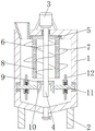
FIG. 1 is a main sectional view of the structure of the present invention;
FIG. 2 is an enlarged cross-sectional view of the fixing plate of the present invention;
fig. 3 is a front view of the mixing drum of the present invention.
In the figure: 1-stirring box, 2-supporting legs, 3-driving motor, 4-rotating shaft, 5-hollow stirring barrel, 6-first spiral stirring blade, 7-second spiral stirring blade, 8-diversion hole, 9-driving conical gear, 10-driven conical gear, 11-stirring cross rod, 12-T-shaped stirring rod, 13-fixed disk and 14-spring.
The specific implementation mode is as follows:
the technical solutions in the embodiments of the present invention will be described clearly and completely with reference to the accompanying drawings in the embodiments of the present invention, and it is obvious that the described embodiments are only some embodiments of the present invention, not all embodiments. Based on the embodiments in the present invention, all other embodiments obtained by a person skilled in the art without creative efforts belong to the protection scope of the present invention.
Referring to fig. 1 to 3, a stirring apparatus for processing powdered mullite into paste comprises a stirring box 1, wherein an inclined plane is formed at the bottom of the inner wall of the stirring box 1, the inclined plane is provided for facilitating discharging, a feed inlet is formed at the left side of the stirring box 1 close to the top, a discharge outlet is formed at the bottom of the stirring box 1, a support leg 2 is fixedly connected to the bottom of the stirring box 1, a driving motor 3 is fixedly connected to the top of the stirring box 1, a rotating shaft 4 is fixedly connected to the output end of the driving motor 3, mullite raw material is firstly put into the stirring box 1 from the feed inlet, then the driving motor 3 is started, the driving motor 3 drives the rotating shaft 4 to rotate, so as to drive a hollow stirring cylinder 5 to rotate, a bearing enables the hollow stirring cylinder 5 to rotate more stably, the bottom end of the rotating shaft 4 penetrates through the top end of the stirring box 1 and is rotatably connected, the top of the inner wall of the stirring box 1 is provided with a groove, the inner wall of the groove is rotatably connected with a hollow stirring cylinder 5 through a bearing, the circumferential inner wall of the hollow stirring cylinder 5 is fixedly connected with a first spiral stirring blade 6, the circumferential surface of the hollow stirring cylinder 5 is fixedly connected with a second spiral stirring blade 7, the rotation directions of the first spiral stirring blade 6 and the second spiral stirring blade 7 are opposite, and under the action of the diversion holes 8, the rotation of the hollow stirring cylinder 5 causes the mullite slurry in the stirring box 1 to generate countercurrent, so that the mullite is stirred more thoroughly and fully, the slurry dissolving of the mullite in the stirring box 1 is more thoroughly and fully, the circumferential surface of the hollow stirring cylinder 5 is provided with the diversion holes 8, the bottom end of the rotating shaft 4 penetrates through the top of the hollow stirring cylinder 5 and is fixedly connected with the hollow stirring cylinder 5, the surface of the rotating shaft 4 close to the bottom end is fixedly connected with a driving bevel gear 9, the surface of the driving bevel gear 9 is meshed with driven bevel gears 10, the number of the driven bevel gears 10 is two, the two driven bevel gears 10 are symmetrically distributed on two sides of the driving bevel gear 9 and are meshed with the surface of the driving bevel gear 9, the two driven bevel gears 10 and a stirring cross rod 11 are arranged to fully stir mullite slurry at the bottom of the stirring box 1, the inner wall of the driven bevel gear 10 is fixedly connected with the stirring cross rod 11, one end of the stirring cross rod 11 far away from the driven bevel gear 10 is rotatably connected with the side surface of the inner wall of the stirring box 1 through a bearing, the surface of the stirring cross rod 11 is connected with a T-shaped stirring rod 12 through a connecting mechanism, the connecting mechanism comprises a fixed disk 13, and the fixed disk 13 is fixedly connected on the surface of the stirring cross, four cavities have been seted up to the equidistant of inner wall of fixed disk 13, and the inner wall fixedly connected with spring 14 of cavity, 4 rotations of axis of rotation can drive initiative conical gear 9 and rotate, initiative conical gear 9 can drive driven conical gear 10 and rotate, thereby drive stirring horizontal pole 11 and rotate, fixed disk 13 rotates and makes under the effect of centrifugal force, T type puddler 12 can outwards move, thereby the stirring range has been changed, make the stirring of mullite thick liquid more thorough, the one end and the T type puddler 12 fixed connection of cavity inner wall are kept away from to spring 14, and T type puddler 12 runs through the edge of fixed disk 13.
The working principle is as follows: when the stirring device for processing powdery mullite into paste is used and needs to stir and change the mullite raw material into slurry, the mullite raw material is firstly put into the stirring box 1 from the feeding hole, then the driving motor 3 is started, the driving motor 3 drives the rotating shaft 4 to rotate so as to drive the hollow stirring cylinder 5 to rotate, the bearing enables the hollow stirring cylinder 5 to rotate more stably, the rotation directions of the first spiral stirring blade 6 and the second spiral stirring blade 7 are opposite, and the mullite slurry in the stirring box 1 can generate countercurrent under the action of the diversion hole 8 when the hollow stirring cylinder 5 rotates, so that the mullite is stirred more thoroughly and completely, the slurry of the mullite in the stirring box 1 is changed more thoroughly, meanwhile, the rotating shaft 4 rotates to drive the driving bevel gear 9 to rotate, the driving bevel gear 9 drives the driven bevel gear 10 to rotate, thereby drive stirring horizontal pole 11 and rotate, fixed disk 13 rotates and makes under the effect of centrifugal force, and T type puddler 12 can outwards move to changed the stirring scope, made the stirring slurrying of mullite thick liquid more thorough, provided the guarantee for spray granulation on next step, thereby improved mullite's bonding property, high temperature oxidation resistance, reduced mullite's density and heat conductivity simultaneously.
The above description is only a preferred embodiment of the present invention, and should not be taken as limiting the invention, and any modifications, equivalent replacements, improvements, etc. made within the spirit and principle of the present invention should be included in the protection scope of the present invention.
Claims (5)
1. The utility model provides a with pasty agitating unit of powdered mullite processing thick liquid, includes agitator tank (1), and agitator tank (1) is close to the left side at top and has seted up the feed inlet, and the discharge gate has been seted up to the bottom of agitator tank (1), the bottom fixedly connected with supporting leg (2) of agitator tank (1), its characterized in that: the top of the stirring box (1) is fixedly connected with a driving motor (3), the output end of the driving motor (3) is fixedly connected with a rotating shaft (4), the bottom end of the rotating shaft (4) penetrates through the top end of the stirring box (1) and is rotatably connected with the top end of the stirring box (1) through a bearing, the top of the inner wall of the stirring box (1) is provided with a groove, the inner wall of the groove is rotatably connected with a hollow stirring cylinder (5) through a bearing, the circumferential inner wall of the hollow stirring cylinder (5) is fixedly connected with a first spiral stirring blade (6), the circumferential surface of the hollow stirring cylinder (5) is fixedly connected with a second spiral stirring blade (7), the circumferential surface of the hollow stirring cylinder (5) is provided with a flow guide hole (8), the bottom end of the rotating shaft (4) penetrates through the top of the hollow stirring cylinder (5) and is fixedly connected with the hollow stirring cylinder (, axis of rotation (4) are close to surperficial fixedly connected with initiative conical gear (9) of bottom, the meshing of the surface of initiative conical gear (9) has driven conical gear (10), the inner wall fixedly connected with stirring horizontal pole (11) of driven conical gear (10), the one end that driven conical gear (10) were kept away from in stirring horizontal pole (11) is passed through the bearing and is connected with the side rotation of agitator tank (1) inner wall, the surface of stirring horizontal pole (11) is connected with T type puddler (12) through coupling mechanism.
2. The stirring device for processing the powdery mullite into the paste state as claimed in claim 1, wherein: the rotating directions of the first spiral stirring blade (6) and the second spiral stirring blade (7) are opposite.
3. The stirring device for processing the powdery mullite into the paste state as claimed in claim 1, wherein: coupling mechanism includes fixed disk (13), fixed disk (13) fixed connection is on the surface of stirring horizontal pole (11), four cavities have been seted up to the inner wall equidistant of fixed disk (13), and the inner wall fixedly connected with spring (14) of cavity, the one end and the T type puddler (12) fixed connection of cavity inner wall are kept away from in spring (14), and the edge of fixed disk (13) is run through in T type puddler (12).
4. The stirring device for processing the powdery mullite into the paste state as claimed in claim 1, wherein: the number of the driven bevel gears (10) is two, and the driven bevel gears (10) are symmetrically distributed on two sides of the driving bevel gear (9) and meshed with the surface of the driving bevel gear (9).
5. The stirring device for processing the powdery mullite into the paste state as claimed in claim 1, wherein: the bottom of the inner wall of the stirring box (1) is provided with an inclined surface.
Priority Applications (1)
| Application Number | Priority Date | Filing Date | Title |
|---|---|---|---|
| CN201920856743.7U CN210138609U (en) | 2019-06-06 | 2019-06-06 | Stirring device for processing powdery mullite into paste |
Applications Claiming Priority (1)
| Application Number | Priority Date | Filing Date | Title |
|---|---|---|---|
| CN201920856743.7U CN210138609U (en) | 2019-06-06 | 2019-06-06 | Stirring device for processing powdery mullite into paste |
Publications (1)
| Publication Number | Publication Date |
|---|---|
| CN210138609U true CN210138609U (en) | 2020-03-13 |
Family
ID=69735083
Family Applications (1)
| Application Number | Title | Priority Date | Filing Date |
|---|---|---|---|
| CN201920856743.7U Active CN210138609U (en) | 2019-06-06 | 2019-06-06 | Stirring device for processing powdery mullite into paste |
Country Status (1)
| Country | Link |
|---|---|
| CN (1) | CN210138609U (en) |
Cited By (3)
| Publication number | Priority date | Publication date | Assignee | Title |
|---|---|---|---|---|
| CN111805786A (en) * | 2020-05-28 | 2020-10-23 | 汪大红 | Agitating unit is used in rubber production processing based on inside backward flow |
| CN111888962A (en) * | 2020-08-03 | 2020-11-06 | 巩莉 | Preparation process of high-molecular water-based paint |
| CN115869890A (en) * | 2023-02-11 | 2023-03-31 | 泰安亚荣生物科技有限公司 | Triethyl phosphate continuous production equipment and method |
-
2019
- 2019-06-06 CN CN201920856743.7U patent/CN210138609U/en active Active
Cited By (4)
| Publication number | Priority date | Publication date | Assignee | Title |
|---|---|---|---|---|
| CN111805786A (en) * | 2020-05-28 | 2020-10-23 | 汪大红 | Agitating unit is used in rubber production processing based on inside backward flow |
| CN111888962A (en) * | 2020-08-03 | 2020-11-06 | 巩莉 | Preparation process of high-molecular water-based paint |
| CN115869890A (en) * | 2023-02-11 | 2023-03-31 | 泰安亚荣生物科技有限公司 | Triethyl phosphate continuous production equipment and method |
| CN115869890B (en) * | 2023-02-11 | 2023-09-29 | 山东亚荣化学股份有限公司 | Continuous production equipment and method for triethyl phosphate |
Similar Documents
| Publication | Publication Date | Title |
|---|---|---|
| CN210138609U (en) | Stirring device for processing powdery mullite into paste | |
| CN211069848U (en) | Mixer for improving granulating uniformity of sinter | |
| CN204746141U (en) | Special mixer of fertilizer formula | |
| CN110559905A (en) | Conical double-screw mixer | |
| CN209682595U (en) | A kind of stir mixing machine | |
| CN208020529U (en) | A kind of plastic grain agitating device | |
| CN109453693A (en) | A kind of food batch mixer | |
| CN111820310A (en) | Energy type chocolate is with compounding agitating unit | |
| CN211164611U (en) | Heat preservation mortar agitated vessel | |
| CN207493592U (en) | Powder batch mixing taper agitating device | |
| CN202983558U (en) | Blender mixer for mixing two kinds of liquid with different densities | |
| CN212119613U (en) | Slurry stirring device with good stirring effect | |
| CN212492537U (en) | Vertical blendor of sodium xanthate | |
| CN212701912U (en) | Production device for biodegradable SMA resin | |
| CN212142313U (en) | Blending device of high-strength energy-saving concrete water reducing agent | |
| CN208097878U (en) | A kind of batch mixer with scraper | |
| CN210252137U (en) | Multifunctional gravity-free mixer | |
| CN207805495U (en) | It is a kind of that agitating shaft and the mixing machine of outer barrel rotation are directly driven by decelerating motor | |
| CN206980505U (en) | A kind of efficient mixing arrangement of composite purifying agent | |
| CN218358964U (en) | Raw material mixing device for chemical resin processing | |
| CN102935339A (en) | Mixer for mixing two liquid with different densities | |
| CN215202859U (en) | Rubber production raw material stirring device | |
| CN210544482U (en) | Horizontal type cement mixer | |
| CN219984540U (en) | Mixing arrangement is used in waterproof coating production | |
| CN209828836U (en) | Corundum miropowder batching agitating unit |
Legal Events
| Date | Code | Title | Description |
|---|---|---|---|
| GR01 | Patent grant | ||
| GR01 | Patent grant |