CN212119613U - Slurry stirring device with good stirring effect - Google Patents
Slurry stirring device with good stirring effect Download PDFInfo
- Publication number
- CN212119613U CN212119613U CN201922436850.7U CN201922436850U CN212119613U CN 212119613 U CN212119613 U CN 212119613U CN 201922436850 U CN201922436850 U CN 201922436850U CN 212119613 U CN212119613 U CN 212119613U
- Authority
- CN
- China
- Prior art keywords
- stirring
- shaft
- mixing
- wall
- driving motor
- Prior art date
- Legal status (The legal status is an assumption and is not a legal conclusion. Google has not performed a legal analysis and makes no representation as to the accuracy of the status listed.)
- Active
Links
Images


Abstract
The utility model provides a ground paste agitating unit that stirring effect is good, including the agitator, first driving motor is installed to the front end of agitator, first driving motor's output is connected with first (mixing) shaft through the rotor rotation, fixed parcel has spiral stirring vane on the outer wall of first (mixing) shaft, just the fixed block has been cup jointed to the one end symmetry of first (mixing) shaft, two install four trapezoidal framves, four on the outer wall of fixed block the inboard center department of trapezoidal frame all is equipped with the connecting rod, just it is connected with second (mixing) shaft and third (mixing) shaft to rotate side by side on the interior bottom plate of agitator, the second (mixing) shaft with the impeller is all installed on the top of third (mixing) shaft, two equal welded fastening has a plurality of stirring fan blades on the outer wall of impeller. The utility model discloses a first (mixing) shaft, spiral stirring vane, trapezoidal frame, second (mixing) shaft, third (mixing) shaft and stirring fan blade have realized the upper and lower even stirring of material, and stirring effect is good.
Description
Technical Field
The utility model mainly relates to a technical field of ground paste agitating unit specifically is a ground paste agitating unit that stirring effect is good.
Background
Among the present ground paste stirring technique, generally mix solid material and liquid material stirring, in order to satisfy the construction demand, the ground paste stirring is not abundant, lead to the adhesion of ground paste to reduce, influence building engineering's quality, current ground paste agitating unit, adopt a agitator to stir the material mostly, though can realize the mixing of raw materials, but the scope of stirring is limited, the stirring effect of the nearer material of distance agitator is better, but the material mixing stirring far away from the agitator is abundant inadequately, lead to the material to mix inhomogeneously, influence the quality of ground paste. Therefore, it is necessary to develop a slurry stirring apparatus having a good stirring effect to improve the stirring effect of the slurry.
SUMMERY OF THE UTILITY MODEL
The utility model mainly provides a slurry stirring device with good stirring effect for solve the technical problem provided in the above background art.
The utility model provides a technical scheme that above-mentioned technical problem adopted does:
a slurry stirring device with good stirring effect comprises a stirring barrel, wherein a first driving motor is horizontally installed at the front end of the stirring barrel, the output end of the first driving motor is connected with a first stirring shaft through a rotor in a rotating mode, one end, far away from the first driving motor, of the first stirring shaft horizontally penetrates through the stirring barrel and extends to the inner side wall of the stirring barrel to be in rotating connection through a ball bearing, a spiral stirring blade is fixedly wrapped on the outer wall of the first stirring shaft, fixed blocks are symmetrically sleeved at one end, far away from the spiral stirring blade, of the first stirring shaft, four trapezoid frames are installed on the outer walls of the two fixed blocks in a staggered mode, the open ends of the four trapezoid frames are respectively and fixedly connected with the outer walls of the two fixed blocks, connecting rods are fixedly welded at the centers of the inner sides of the four trapezoid frames, and a second stirring shaft and a third stirring shaft are vertically and rotatably connected with the inner bottom plate of the stirring, impellers are arranged at the top ends of the second stirring shaft and the third stirring shaft, and a plurality of stirring fan blades are welded and fixed on the outer walls of the impellers in a staggered mode.
Further, a supporting box is installed perpendicularly to the bottom of agitator, install the runner assembly in the cavity of supporting box, the runner assembly includes second driving motor, second driving motor's output is connected with straight-tooth bevel gear through the flat key rotation, straight-tooth bevel gear keeps away from one side meshing of second driving motor is connected with bevel gear, install first straight gear directly over bevel gear perpendicularly, one side of first straight gear is connected with the second straight gear through the chain meshing, just first straight gear with the second straight gear is located respectively the second (mixing) shaft with under the third (mixing) shaft.
Further, the second (mixing) shaft is kept away from two the one end of impeller runs through perpendicularly in proper order the agitator first spur gear with bevel gear extends to the infrabasal plate of supporting box is through ball bearing and rotates the connection, just two are kept away from to the third (mixing) shaft the one end of impeller runs through perpendicularly in proper order the agitator with the second spur gear extends to the infrabasal plate of supporting box is through ball bearing and rotates the connection.
Further, the top center department of agitator installs the feeder hopper, it is connected with the feed plate to rotate through universal ball on the inner wall of feeder hopper, the vibrator is installed perpendicularly to the bottom center department of feed plate, the bottom of feed plate is close to outer edgewise symmetry and installs elastic connecting piece, two elastic connecting piece keeps away from the one end of feed plate all with the inner wall fixed connection of feeder hopper.
Furthermore, a discharge hopper is vertically installed at the bottom end of the stirring barrel close to the outer edge, and a clamping groove is formed in the inner wall of the discharge hopper.
Furthermore, the rear end horizontal installation of play hopper is equipped with the baffle, the one end of baffle runs through it extends to its inside welded fastening has the fixture block to go out the hopper, the fixture block with the draw-in groove joint is connected, just the baffle is kept away from the one end welded fastening of fixture block has the pull ring.
Furthermore, a plurality of fixing plates are spirally welded and fixed on the inner wall of the stirring barrel.
Compared with the prior art, the beneficial effects of the utility model are that:
one of the two, the utility model discloses an even mixing of ground paste, stirring effect is good, through the work of first driving motor, drive first (mixing) shaft and rotate, first (mixing) shaft drives spiral stirring vane and trapezoidal frame rotation, carry out the stirring in the horizontal direction to the material through spiral stirring vane's rotation, carry the material to the position of hopper when stirring, further stir the material through rotatory trapezoidal frame, later through the rotation of second (mixing) shaft and third (mixing) shaft, drive the impeller rotation, drive the stirring flabellum rotation through the rotation of impeller, carry out the stirring in the vertical direction to the material through the rotation of stirring flabellum, the upper and lower even stirring of material has been realized, stirring effect has been improved;
and secondly, the utility model discloses a runner assembly simple structure is convenient for realize, is fit for bulk production, through second driving motor work, and drive straight bevel gear is rotatory, because straight bevel gear is connected with bevel gear's meshing, drives the second (mixing) shaft and rotates, because first straight gear passes through the chain and is connected with second straight gear meshing, consequently drives the third (mixing) shaft and rotates, has realized the rotation of second (mixing) shaft and third (mixing) shaft, and rotating-structure is simple, is convenient for realize, is fit for producer's bulk production.
The present invention will be explained in detail with reference to the drawings and specific embodiments.
Drawings
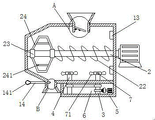
Fig. 1 is a schematic view of the overall structure of the present invention;
FIG. 2 is a sectional view of the internal structure of the mixing tank of the present invention;
FIG. 3 is a schematic structural view of the rotating assembly of the present invention;
FIG. 4 is an enlarged view of area A in FIG. 2;
fig. 5 is an enlarged view of region B in fig. 2.
In the figure: 1. a stirring barrel; 11. a feed hopper; 12. a discharge hopper; 121. a card slot; 13. a fixing plate; 14. a baffle plate; 141. a pull ring; 142. a clamping block; 15. a feeding plate; 151. an elastic connecting member; 152. a vibrator; 2. a first stirring shaft; 21. a first drive motor; 22. a helical mixing blade; 23. a fixed block; 24. a ladder frame; 241. a connecting rod; 3. a second stirring shaft; 4. a third stirring shaft; 5. a support box; 6. a rotating assembly; 61. a second drive motor; 62. a straight bevel gear; 63. a bevel gear; 64. a first straight gear; 65. a second spur gear; 7. an impeller; 71. stirring fan blades.
Detailed Description
In order to facilitate understanding of the present invention, the present invention will be described more fully with reference to the accompanying drawings, in which several embodiments of the present invention are shown, but the present invention can be implemented in different forms, and is not limited to the embodiments described in the text, but rather, these embodiments are provided to make the disclosure of the present invention more thorough and comprehensive.
It will be understood that when an element is referred to as being "secured to" another element, it can be directly on the other element or intervening elements may be present, and when an element is referred to as being "connected" to another element, it can be directly connected to the other element or intervening elements may also be present, as the terms "vertical", "horizontal", "left", "right" and the like are used herein for descriptive purposes only.
Unless defined otherwise, all technical and scientific terms used herein have the same meaning as commonly understood by one of ordinary skill in the art to which this invention belongs, and the use of the term knowledge in the specification of the present invention is for the purpose of describing particular embodiments and is not intended to limit the present invention, and the term "and/or" as used herein includes any and all combinations of one or more of the associated listed items.
Please refer to fig. 1-5 in greater detail, a slurry stirring apparatus with good stirring effect comprises a stirring barrel 1, a first driving motor 21 is horizontally installed at the front end of the stirring barrel 1, the output end of the first driving motor 21 is connected with a first stirring shaft 2 through a rotor, one end of the first stirring shaft 2 far away from the first driving motor 21 horizontally penetrates through the stirring barrel 1 and extends to the inner side wall thereof to be connected through a ball bearing in a rotating manner, a helical stirring blade 22 is fixedly wrapped on the outer wall of the first stirring shaft 2, one end of the first stirring shaft 2 far away from the helical stirring blade 22 is symmetrically sleeved with fixed blocks 23, four trapezoidal frames 24 are installed on the outer walls of the two fixed blocks 23 in a staggered manner, the open ends of the four trapezoidal frames 24 are respectively fixedly connected with the outer walls of the two fixed blocks 23, and connecting rods 241 are welded and fixed at the centers of the inner sides of the four trapezoidal frames 24, and the interior bottom plate of agitator 1 is gone up and is rotated perpendicularly side by side and is connected with second (mixing) shaft 3 and third (mixing) shaft 4, impeller 7, two are all installed to second (mixing) shaft 3 with the top of third (mixing) shaft 4 all crisscross welded fastening has a plurality of stirring fan blades 71 on the outer wall of impeller 7, spiral welded fastening has a plurality of fixed plates 13 on the inner wall of agitator 1. In this embodiment, the slurry is sheared by the plurality of fixing plates 13 provided spirally, thereby improving the slurry stirring effect.
Please refer to fig. 1 and fig. 4, the top center of the mixing tank 1 is provided with a feeding hopper 11, the inner wall of the feeding hopper 11 is rotatably connected with a feeding plate 15 through a universal ball, the bottom center of the feeding plate 15 is vertically provided with a vibrator 152, the bottom of the feeding plate 15 near the outer edge is symmetrically provided with elastic connecting members 151, and one ends of the two elastic connecting members 151 far away from the feeding plate 15 are fixedly connected with the inner wall of the feeding hopper 11. In this embodiment, through the work of vibrator 152, because the feed plate 15 passes through the inner wall fixed connection of universal ball feeder hopper 11, consequently the feed plate 15 vibrates, under the effect of vibration, has prolonged the dwell time of material, can evenly spill the material in agitator 1 simultaneously, has improved stirring effect, through elastic connection piece 151 firm support feed plate 15.
Please refer to fig. 1 and fig. 5, a discharge hopper 12 is vertically installed at the bottom end of the mixing tank 1 near the outer edge, a clamping groove 121 is disposed on the inner wall of the discharge hopper 12, a baffle plate 14 is horizontally installed at the rear end of the discharge hopper 12, one end of the baffle plate 14 penetrates through the discharge hopper 12 and extends to the inside of the discharge hopper 12, a clamping block 142 is fixedly welded therein, the clamping block 142 is connected with the clamping groove 121 in a clamping manner, and a pull ring 141 is fixedly welded at one end of the baffle plate 14 far from the clamping block 142. In this embodiment, the pull ring 141 pulls the baffle 14 outwards, so that the size of the discharge space of the hopper 12 can be adjusted, and the baffle 14 is stabilized by clamping the clamping block 142 with the clamping groove 121.
Please refer to fig. 2-3 heavily, a support box 5 is vertically installed at the bottom of the stirring barrel 1, a rotating component 6 is installed in a cavity of the support box 5, the rotating component 6 includes a second driving motor 61, an output end of the second driving motor 61 is connected with a straight bevel gear 62 through a flat key rotation, one side of the straight bevel gear 62 away from the second driving motor 61 is connected with a bevel gear 63 in a meshing manner, a first straight gear 64 is installed right above the bevel gear 63, one side of the first straight gear 64 is connected with a second straight gear 65 through a chain in a meshing manner, the first straight gear 64 and the second straight gear 65 are respectively located right below the second stirring shaft 3 and the third stirring shaft 4, one end of the second stirring shaft 3 away from the two impellers 7 sequentially and vertically penetrates through the stirring barrel 1, the first straight gear 64 and the bevel gear 63, and extends to an inner bottom plate of the support box 5 through a ball bearing Be and rotate the connection, just third (mixing) shaft 4 keeps away from two the one end of impeller 7 runs through perpendicularly in proper order agitator 1 with second spur gear 65 extends to the infrabasal plate of supporting box 5 is through ball bearing and rotates the connection. In this embodiment, the second driving motor 61 is operated to drive the straight bevel gear 62 to rotate, the straight bevel gear 62 is engaged with the bevel gear 63 to drive the second stirring shaft 3 to rotate, the first straight gear 64 is engaged with the second straight gear 65 via a chain to drive the third stirring shaft 4 to rotate, the impeller 7 is driven to rotate, the stirring fan blades 71 are driven to rotate by the rotation of the impeller 7, and the material is stirred by the rotation of the stirring fan blades 71.
The utility model discloses a concrete operation as follows:
firstly, materials are poured into the stirring barrel 1 from the feeding hopper 11, the vibrator 152 works, the feeding plate 15 is fixedly connected with the inner wall of the universal ball feeding hopper 11 through the feeding plate 15, so that the feeding plate 15 vibrates to uniformly scatter the materials in the stirring barrel 1, then the first driving motor 21 works to drive the first stirring shaft 2 to rotate, the first stirring shaft 2 drives the spiral stirring blade 22 and the trapezoid frame 24 to rotate, the materials are stirred in the horizontal direction through the rotation of the spiral stirring blade 22, the materials are conveyed to the position of the discharging hopper 12 while being stirred, the materials are further stirred through the rotating trapezoid frame 24, then the second driving motor 61 works to drive the straight bevel gear 62 to rotate, the straight bevel gear 62 is meshed with the bevel gear 63 to drive the second stirring shaft 3 to rotate, and the first straight gear 64 is meshed with the second straight gear 65 through a chain, therefore, the third stirring shaft 4 is driven to rotate, the impeller 7 is driven to rotate, the stirring fan blades 71 are driven to rotate through the rotation of the impeller 7, the materials are stirred in the vertical direction through the rotation of the stirring fan blades 71, the materials are stirred and mixed up and down, the stirring effect is good, after the stirring is completed, the baffle 14 is pulled outwards through the pull ring 141, and the stirred slurry is conveyed out from the discharge hopper 12.
The present invention has been described above with reference to the accompanying drawings, and it is obvious that the present invention is not limited by the above-mentioned manner, if the method and the technical solution of the present invention are adopted, the present invention can be directly applied to other occasions without substantial improvement, and the present invention is within the protection scope of the present invention.
Claims (7)
1. The slurry stirring device with good stirring effect comprises a stirring barrel (1) and is characterized in that a first driving motor (21) is horizontally installed at the front end of the stirring barrel (1), the output end of the first driving motor (21) is connected with a first stirring shaft (2) through rotation of a rotor, one end of the first stirring shaft (2) far away from the first driving motor (21) horizontally penetrates through the stirring barrel (1) and extends to the inner side wall of the stirring barrel to be in rotating connection through a ball bearing, spiral stirring blades (22) are fixedly wrapped on the outer wall of the first stirring shaft (2), fixed blocks (23) are symmetrically sleeved at one ends of the first stirring shaft (2) far away from the spiral stirring blades (22), four trapezoidal frames (24) are installed on the outer wall of the two fixed blocks (23) in a staggered mode, and the open ends of the four trapezoidal frames (24) are respectively fixedly connected with the outer walls of the two fixed blocks (23), four equal welded fastening in inboard center department of trapezoidal frame (24) has connecting rod (241), just it is connected with second (mixing) shaft (3) and third (mixing) shaft (4) to rotate side by side perpendicularly on the interior bottom plate of agitator (1), second (mixing) shaft (3) with impeller (7), two are all installed on the top of third (mixing) shaft (4) all crisscross welded fastening has a plurality of stirring fan blades (71) on the outer wall of impeller (7).
2. The slurry stirring apparatus having a good stirring effect according to claim 1, a supporting box (5) is vertically arranged at the bottom of the stirring barrel (1), a rotating component (6) is arranged in a cavity of the supporting box (5), the rotating assembly (6) comprises a second driving motor (61), the output end of the second driving motor (61) is rotationally connected with a straight bevel gear (62) through a flat key, one side of the straight bevel gear (62) far away from the second driving motor (61) is connected with a bevel gear (63) in a meshing way, a first straight gear (64) is arranged right above the bevel gear (63), one side of the first straight gear (64) is connected with a second straight gear (65) through a chain in a meshing way, and the first straight gear (64) and the second straight gear (65) are respectively positioned under the second stirring shaft (3) and the third stirring shaft (4).
3. The slurry stirring device with good stirring effect as recited in claim 2, wherein one end of the second stirring shaft (3) far away from the two impellers (7) sequentially and vertically penetrates through the stirring barrel (1), the first spur gear (64) and the bevel gear (63) to extend to the inner bottom plate of the supporting box (5) to be rotationally connected through a ball bearing, and one end of the third stirring shaft (4) far away from the two impellers (7) sequentially and vertically penetrates through the stirring barrel (1) and the second spur gear (65) to extend to the inner bottom plate of the supporting box (5) to be rotationally connected through a ball bearing.
4. The slurry stirring device with good stirring effect as claimed in claim 2, wherein a feed hopper (11) is installed at the top center of the stirring barrel (1), a feed plate (15) is rotatably connected to the inner wall of the feed hopper (11) through a universal ball, a vibrator (152) is vertically installed at the bottom center of the feed plate (15), elastic connecting pieces (151) are symmetrically installed at the bottom of the feed plate (15) close to the outer edge, and one ends of the two elastic connecting pieces (151) far away from the feed plate (15) are fixedly connected with the inner wall of the feed hopper (11).
5. The slurry stirring device with good stirring effect as claimed in claim 4, wherein a discharge hopper (12) is vertically installed at the bottom end of the stirring barrel (1) close to the outer edge, and a clamping groove (121) is arranged on the inner wall of the discharge hopper (12).
6. The slurry stirring device with good stirring effect as recited in claim 5, wherein a baffle plate (14) is horizontally installed at the rear end of the discharge hopper (12), one end of the baffle plate (14) extends through the discharge hopper (12) and is fixedly welded to a fixture block (142) inside, the fixture block (142) is connected with the fixture groove (121) in a clamping manner, and a pull ring (141) is fixedly welded to one end of the baffle plate (14) far away from the fixture block (142).
7. The slurry stirring apparatus with good stirring effect as claimed in claim 5, wherein a plurality of fixing plates (13) are fixed to the inner wall of the stirring barrel (1) by screw welding.
Priority Applications (1)
| Application Number | Priority Date | Filing Date | Title |
|---|---|---|---|
| CN201922436850.7U CN212119613U (en) | 2019-12-30 | 2019-12-30 | Slurry stirring device with good stirring effect |
Applications Claiming Priority (1)
| Application Number | Priority Date | Filing Date | Title |
|---|---|---|---|
| CN201922436850.7U CN212119613U (en) | 2019-12-30 | 2019-12-30 | Slurry stirring device with good stirring effect |
Publications (1)
| Publication Number | Publication Date |
|---|---|
| CN212119613U true CN212119613U (en) | 2020-12-11 |
Family
ID=73676492
Family Applications (1)
| Application Number | Title | Priority Date | Filing Date |
|---|---|---|---|
| CN201922436850.7U Active CN212119613U (en) | 2019-12-30 | 2019-12-30 | Slurry stirring device with good stirring effect |
Country Status (1)
| Country | Link |
|---|---|
| CN (1) | CN212119613U (en) |
Cited By (1)
| Publication number | Priority date | Publication date | Assignee | Title |
|---|---|---|---|---|
| CN115974558A (en) * | 2023-01-10 | 2023-04-18 | 中硼科技(威海)有限公司 | Boron carbide-based neutron absorption material and preparation method thereof |
-
2019
- 2019-12-30 CN CN201922436850.7U patent/CN212119613U/en active Active
Cited By (2)
| Publication number | Priority date | Publication date | Assignee | Title |
|---|---|---|---|---|
| CN115974558A (en) * | 2023-01-10 | 2023-04-18 | 中硼科技(威海)有限公司 | Boron carbide-based neutron absorption material and preparation method thereof |
| CN115974558B (en) * | 2023-01-10 | 2023-12-05 | 中硼科技(威海)有限公司 | Boron carbide-based neutron absorption material and preparation method thereof |
Similar Documents
| Publication | Publication Date | Title |
|---|---|---|
| CN204746141U (en) | Special mixer of fertilizer formula | |
| CN212119613U (en) | Slurry stirring device with good stirring effect | |
| CN213674906U (en) | Raw materials flash mixed device of rubber component processing usefulness | |
| CN109453693A (en) | A kind of food batch mixer | |
| CN209320004U (en) | Twin shaft concrete batch plant based on open type gear driving | |
| CN107498730B (en) | A kind of PVC film material stirrer | |
| CN216964400U (en) | High remanence and high coercivity magnet steel production are with mixing powder device | |
| CN213260417U (en) | Stirring device with uniform discharging function for quartz stone production | |
| CN211279123U (en) | Preparation device for adhesive mortar of external wall insulation board | |
| CN211677241U (en) | Horizontal double helix area feed mixer | |
| CN210278949U (en) | Civil engineering agitating unit | |
| CN210705451U (en) | Automatic mix material and carry and send device | |
| CN208878405U (en) | A kind of energy-saving powder homogenization installation | |
| CN108312338A (en) | A kind of efficient mortar blender | |
| CN213433964U (en) | Blast furnace carbon brick preparation facilities convenient to homogeneous mixing | |
| CN217392198U (en) | Raw material stirring device for preparing spherical boron nitride | |
| CN217020968U (en) | Mixing device for producing cement mortar by using phosphogypsum | |
| CN209646819U (en) | A kind of spiral AB glue mixing apparatus goes out plastic structure | |
| CN219543643U (en) | Cement telegraph pole production batching agitating unit | |
| CN216803941U (en) | High-efficient mortar mixing apparatus | |
| CN216062761U (en) | Powder processing agitating unit | |
| CN110385082B (en) | Anti-vortex inclined conveying type industrial material stirrer and working method thereof | |
| CN218688962U (en) | Stirrer for putty powder production | |
| CN217016326U (en) | Mixer for production and processing of hot melt adhesive with uniform stirring | |
| CN215189041U (en) | Aleurone layer and flour premixing device |
Legal Events
| Date | Code | Title | Description |
|---|---|---|---|
| GR01 | Patent grant | ||
| GR01 | Patent grant |