CN210132673U - Rotation type rivers cutting plastics forming device - Google Patents
Rotation type rivers cutting plastics forming device Download PDFInfo
- Publication number
- CN210132673U CN210132673U CN201920620534.2U CN201920620534U CN210132673U CN 210132673 U CN210132673 U CN 210132673U CN 201920620534 U CN201920620534 U CN 201920620534U CN 210132673 U CN210132673 U CN 210132673U
- Authority
- CN
- China
- Prior art keywords
- box
- water
- cylinder
- storage tank
- pipe
- Prior art date
- Legal status (The legal status is an assumption and is not a legal conclusion. Google has not performed a legal analysis and makes no representation as to the accuracy of the status listed.)
- Active
Links
Images


Landscapes
- Processing And Handling Of Plastics And Other Materials For Molding In General (AREA)
Abstract
The utility model discloses a rotary water flow cutting plastic forming device, which comprises a first water storage tank and a second water storage tank, wherein the top of the first water storage tank is provided with an installation box and a granulation box, the installation box is provided with a hydraulic cylinder and a heating box, a push rod of the hydraulic cylinder extends into the heating box and is connected with a first push plate in a welding way, the top of the heating box is communicated with a storage box, the outer side of the heating box is provided with a plurality of heating coils, the right end of the heating box is provided with a discharging pipe, and the discharging pipe extends into the granulation box; the upper portion of pelletization case is equipped with the inlet tube, the inlet tube stretches into the pelletization incasement and links to each other with rotation type variable speed rivers shaping unit. The utility model provides an easily glue glutinous, the overheated brittle problem of plastics when mechanical blade cuts.
Description
Technical Field
The utility model relates to a plastics processing technology field, concretely relates to rotation type rivers cutting plastic forming device.
Background
The common plastic is difficult to decompose and seriously damages the environment, so that some waste plastics need to be recycled, and the waste plastics need to be processed again after being washed and stirred in a series. Most of the existing plastic processing methods adopt that raw materials are heated to be in a molten state and then are cut by a mechanical blade, materials are easily adhered to the blade during processing, and a plastic product is easily overheated and embrittled. So that the product does not meet the standard and the raw material is wasted.
SUMMERY OF THE UTILITY MODEL
The utility model provides a technical problem lie in overcoming prior art's defect, provide a rotation type rivers cutting plastic forming device.
The utility model discloses a following technical scheme realizes:
the utility model provides a rotation type rivers cutting plastic forming device, includes first water storage box, second water storage box, install bin, pneumatic cylinder, heating cabinet, first push pedal, storage case, pelletization case, heating coil, discharging pipe, first support, second support, inlet tube, booster pump, variable speed rivers shaping unit.
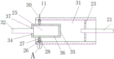
First water storage box and second water storage box communicate mutually, the top of first water storage box is equipped with install bin, pelletization case, install first support, second support on the install bin, install the pneumatic cylinder on the first support, install the heating cabinet on the second support, the push rod of pneumatic cylinder stretches into to link to each other with first push pedal welding in the heating cabinet, the top of heating cabinet is equipped with the feed inlet, the feed inlet is linked together with the storage case, a plurality of heating coil is installed in the outside of heating cabinet, the discharging pipe is installed to the right-hand member of heating cabinet, the discharging pipe stretches into in the pelletization case.
The upper portion of pelletization case is equipped with the inlet tube, the left side wall that the one end of inlet tube passed the pelletization case is stretched into and is linked to each other with rotation type variable speed rivers shaping unit in the pelletization case, install the booster pump on the inlet tube, the other end downwardly extending of inlet tube is to the second water storage box in.
Furthermore, rotation type variable speed rivers shaping unit includes a section of thick bamboo of intaking, connecting pipe, connector, rotatory section of thick bamboo, ring channel, third apopore, spray tube, shower nozzle, connecting plate, rotation axis, servo motor, third support, mounting panel.
The left end of a section of thick bamboo of intaking links to each other with the inlet tube that stretches into the pelletization incasement, the right-hand member of a section of thick bamboo of intaking stretches into the inside of a rotatory section of thick bamboo, just a section of thick bamboo of intaking is on same straight line with the central axis of a rotatory section of thick bamboo, be equipped with the ring channel on the inner wall of a rotatory section of thick bamboo, the right side welding of a rotatory section of thick bamboo inner wall has the connecting plate, the rotation axis is installed at the center of connecting plate, the rotation axis links to each other with servo motor's output shaft, servo motor passes through.
The water inlet cylinder consists of a left sealing plate, a right sealing plate and a cylinder body, the left sealing plate and the right sealing plate are respectively welded at the left end and the right end of the cylinder body, a threaded hole is formed in the left sealing plate, the threaded hole is connected with a water inlet pipe extending into the granulating box in a threaded sealing connection mode, a plurality of uniformly distributed connecting pipes are mounted on the cylinder body, one ends of the connecting pipes are communicated with the inside of the cylinder body, and a connector is mounted at the other ends of the connecting pipes; the connector is located the ring channel on the rotatory section of thick bamboo inner wall, the shape size and the annular groove looks adaptation of connector, evenly be equipped with a plurality of third apopores in the ring channel, install the spray tube in the third apopore, the spray tube passes rotatory section of thick bamboo and links to each other with the shower nozzle.
Further, the connector is hollow spheroid, adopts the rubber preparation to form, the connector is being equipped with second inlet opening, second apopore along the axis direction of connecting pipe, the connecting pipe inserts in the second inlet opening, with powerful gluey sealing connection between the outer wall of connecting pipe and the inner wall of second inlet opening.
Furthermore, the spray head is positioned above the right end of the discharge pipe and is provided with a flat outlet, and the sprayed high-pressure water flow is flaky.
Furthermore, a filter screen groove is arranged above the second water storage tank and welded and installed on the right side wall of the first water storage tank; pelletization case right side bottom is equipped with first apopore, first apopore links to each other through gluing with the outlet pipe, the outlet pipe is located directly over the filter screen groove.
Furthermore, the filter screen groove is U-shaped, a filter screen is arranged at the bottom end of the filter screen groove, and the aperture of the mesh of the filter screen is smaller than the size of the formed plastic particles.
Compared with the prior art, the utility model discloses following beneficial effect has:
the utility model discloses a pour into in the raw materials gets into the heating case from the storage case, then promote first push pedal through the pneumatic cylinder and melt raw and other materials to heating coil department heating, the rethread discharging pipe is sent into to the pelletization incasement, carry the water under high pressure to the section of thick bamboo of intaking through booster pump and inlet tube in the ejection of compact, the rethread connecting pipe gets into the connector, meanwhile servo motor passes through the rotation axis and drives a rotatory section of thick bamboo and rotate, make connector and third apopore intermittent type nature aim at, thereby make the water under high pressure from connector intermittent type nature flow direction spray tube, again from shower nozzle pulsed blowout, thereby reach the purpose of variable. The cut material flows into the bottom end of the granulation box along with water, flows into the filter screen groove through the water outlet pipe, filters water through the filter screen groove, and the filtered water circulates into the second water storage tank again.
The utility model discloses not only control the pulse frequency that the shower nozzle sprayed water through control servo motor rotation rate to adjust and control the speed of cutting the material and the size of plastic granules in a flexible way, easily glue glutinous, the overheated brittle problem of plastics when having solved the cutting of mechanical blade. Meanwhile, the water flow cutting can enable the material to be cooled and solidified more quickly, so that the plastic particles are high in forming speed, compact in texture and convenient to adjust. The utility model provides a hydroenergy can carry out cyclic utilization, has practiced thrift the water resource, accords with national sustainable development scientific development and sees.
Drawings
Fig. 1 is a schematic structural diagram of the present invention.
Fig. 2 is a front view of the rotary variable speed water flow forming unit of the present invention.
Fig. 3 is a partially enlarged view of a portion a in fig. 2.
Fig. 4 is a side view of a rotary variable speed water flow shaping unit of the present invention.
In the drawing, 1, a first water storage tank, 2, a second water storage tank, 3, an installation tank, 4, a hydraulic cylinder, 5, a heating tank, 6, a first push plate, 7, a material storage tank, 8, a heating coil, 9, a discharge pipe, 10, a water outlet pipe, 11, a spray head, 12, a granulation tank, 13, a communication hole, 14, a booster pump, 15, a filter screen groove, 16, a feed inlet, 17, a first support, 18, a second support, 19, a third support, 20, a servo motor, 21, a rotating shaft, 22, an installation plate, 23, a connection plate, 24, a first water outlet, 25, a water inlet cylinder, 26, a connector, 27, a connection pipe, 28, an annular groove, 29, a third water outlet, 30, a spray pipe, 31, a rotating cylinder, 32, a water inlet pipe, 33, a first water inlet hole, 34, a left sealing plate, 35, a right sealing plate, 36, a cylinder body, 37, a threaded hole, 38, a second water.
Detailed Description
The present invention will be further described with reference to the following embodiments. Wherein the showings are for the purpose of illustration only and are shown by way of illustration only and not in actual form, and are not to be construed as limiting the present patent; for a better understanding of the embodiments of the present invention, some parts of the drawings may be omitted, enlarged or reduced, and do not represent the size of an actual product; it will be understood by those skilled in the art that certain well-known structures in the drawings and descriptions thereof may be omitted.
As shown in fig. 1-4, a rotary water flow cutting plastic molding device comprises a first water storage tank 1, a second water storage tank 2, an installation box 3, a hydraulic cylinder 4, a heating box 5, a first push plate 6, a material storage box 7, a heating coil 8, a discharge pipe 9, a water outlet pipe 10, a spray head 11, a granulation box 12, a communication hole 13, a booster pump 14, a filter screen groove 15, a feed inlet 16, a first support 17, a second support 18, a third support 19, a servo motor 20, a rotating shaft 21, an installation plate 22, a connection plate 23, a first water outlet hole 24, a water inlet cylinder 25, a connector 26, a connection pipe 27, an annular groove 28, a third water outlet hole 29, a spray pipe 30, a rotating cylinder 31, a water inlet pipe 32, a left sealing plate 34, a right sealing plate 35, a cylinder 36, a threaded hole 37, a second water.
The right side of the first water storage tank 1 is connected with a second water storage tank 2 in a welding mode, and the second water storage tank 2 is communicated with the bottom of the first water storage tank 1 through a communication hole 13. The first water storage tank 1 and the second water storage tank 2 are rectangular hollow boxes and are formed by welding stainless steel plates, and tap water or purified water is stored inside the water storage tanks.
And a filter screen groove 15 is arranged above the second water storage tank 2, and the filter screen groove 15 is welded and installed on the right side wall of the first water storage tank 1. The top of the first water storage tank 1 is provided with an installation tank 3 and a granulation tank 12 in a bolt fixing or welding mode. First support 17, second support 18 are installed through bolt fastening or welded mode to install case 3, install pneumatic cylinder 4 on the first support 17, install heating cabinet 5 on the second support 18.
And a push rod of the hydraulic cylinder 4 extends into the heating box 5 and is connected with the first push plate 6 in a welding mode. The heating box 5 is a cylindrical hollow box body, and the shape and size of the first push plate 6 are matched with the inner cavity of the heating box 5 and can slide back and forth along the inner cavity of the heating box 5. A feed inlet 16 is arranged at the top of the heating box 5, and the feed inlet 16 is communicated with the material storage box 7. And a plurality of heating coils 8 are wound and installed on the outer side of the heating box 5, and the heating coils 8 are connected with an external 220V power supply and used for heating the raw materials entering the heating box 5. The right end of the heating box 5 is provided with a discharge pipe 9, and the discharge pipe 9 extends into the granulating box 12. 12 right side bottom of pelletization case is equipped with first apopore 24, first apopore 24 links to each other through gluing with outlet pipe 10, outlet pipe 10 is located directly over filter screen groove 15. The filter screen groove 15 is U-shaped, a filter screen is arranged at the bottom end of the filter screen groove 15, and the aperture of the mesh of the filter screen is smaller than the size of the formed plastic particles.
The upper portion of pelletization case 12 is equipped with inlet tube 32, first inlet opening 33 on the left side wall of pelletization case 12 is passed to the one end of inlet tube 32, stretches into and links to each other with rotation type variable speed rivers shaping unit in the pelletization case 12, install the booster pump 14 on the inlet tube 32, the other end downwardly extending of inlet tube 32 to the bottom of second water storage box 2.
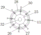
As shown in fig. 2, 3 and 4, the rotary variable-speed water flow forming unit includes a water inlet cylinder 25, a connecting pipe 27, a connecting head 26, a rotary cylinder 31, an annular groove 28, a third water outlet 29, a spray pipe 30, a spray head 11, a connecting plate 23, a rotary shaft 21, a servo motor 20, a third support 19 and a mounting plate 22.
The left end of the water inlet cylinder 25 is connected with a water inlet pipe 32 extending into the granulating tank 12, the right end of the water inlet cylinder 25 extends into the rotating cylinder 31, and the central axes of the water inlet cylinder 25 and the rotating cylinder 31 are on the same straight line. The rotary drum 31 is of a hollow circular tubular structure, an annular groove 28 is formed in the left side of the inner wall of the rotary drum 31, a circular connecting plate 23 is welded to the right side of the inner wall of the rotary drum 31, a rotary shaft 21 is welded to the center of the connecting plate 23, and the rotary shaft 21 is connected with an output shaft of the servo motor 20 through a coupler. The servo motor 20 is mounted on a mounting plate 22 through a third support 19, and the mounting plate 22 is welded and mounted on the inner wall of the right side of the granulating tank 12.
The section of thick bamboo 25 of intaking is formed by left shrouding 34, right shrouding 35, the welding of barrel 36, barrel 36 is circular tubular structure, left side shrouding 34, right shrouding 35 weld respectively at both ends about barrel 36, be equipped with screw hole 37 on the left side shrouding 34, screw hole 37 links to each other with the inlet tube 32 that stretches into in the pelletization case 12 through the mode of screw thread sealing connection, install a plurality of evenly distributed's connecting pipe 27 on the barrel 36, the one end of connecting pipe 27 communicates with each other with barrel 36 is inside, connector 26 is installed to the other end of connecting pipe 27. Connector 26 is hollow spheroid, adopts the rubber preparation to form, connector 26 is being equipped with second inlet opening 38, second apopore 39 along the axis direction of connecting pipe 27, connecting pipe 27 inserts in second inlet opening 38, with super glue sealing connection between the outer wall of connecting pipe 27 and the inner wall of second inlet opening 38.
The utility model discloses a pour into raw materials from storage case 7 and get into heating cabinet 5 in, then promote first push pedal 6 through pneumatic cylinder 4 and melt raw and other materials to 8 heats of heating coil, 9 send into to pelletization incasement 12 in rethread discharging pipe, carry the water under high pressure to the inlet cylinder 25 in through booster pump 14 and inlet tube 32 in the ejection of compact, rethread connecting pipe 27 gets into connector 26, meanwhile servo motor 20 drives rotatory section of thick bamboo 31 through rotation axis 21 and rotates, make connector 26 and 29 intermittent type of third apopore aim at, thereby make the water under high pressure from 26 intermittent type flow direction spray tubes 30 of connector, again from 11 pulsed blowout of shower nozzle, thereby reach the purpose of variable speed pulsed rivers high-pressure cutting material. The cut material flows with the water to the bottom of the granulation tank 12, flows through the outlet pipe 10 into the filter screen tank 15, filters the water through the filter screen tank 15, and the filtered water is recirculated to the second water reservoir 2.
The utility model discloses not only control the pulse frequency that 11 water sprays of shower nozzles through control servo motor 20 rotation rate to adjust in a flexible way and control the speed of cutting material and plastic granules's size, easily glue glutinous, the easy overheated deformation of plastics, the problem of overheated embrittlement when solving the cutting of mechanical blade. Meanwhile, the material can be cooled and solidified more quickly by water flow cutting, so that the plastic particles are formed more quickly, the texture is tighter, the speed is convenient to adjust, the product quality and the yield are greatly improved, and the problem that the size of the plastic particles cannot be adjusted flexibly in the existing equipment is also solved. The utility model provides a hydroenergy can carry out cyclic utilization, has practiced thrift the water resource, accords with national sustainable development scientific development and sees. The utility model discloses go on in an overall seal's container, concentrate on the peculiar smell of plastics heating in pelletization case 12, can not be excessive, can not pollute peripheral air, kept operational environment's clean and cleanness, peculiar smell and harmful gas that produce when having prevented the plastics heating are to operative employee's health harm, have solved the difficult problem that the ubiquitous smell is big among the current plastic processing, contaminated air.
The above description is only the preferred embodiment of the present invention, and the protection scope of the present invention is not limited to the above embodiments. It should be noted that, for those skilled in the art, without departing from the principle of the present invention, several improvements and decorations, such as changing the hydraulic cylinder into a cylinder or a linear servo motor, should also be regarded as the protection scope of the present invention. All the components not specified in the present embodiment can be realized by the prior art.
Claims (6)
1. The utility model provides a rotation type rivers cutting plastic forming device which characterized in that: the device comprises a first water storage tank, a second water storage tank, an installation tank, a hydraulic cylinder, a heating tank, a first push plate, a material storage tank, a granulation tank, a heating coil, a material discharging pipe, a first support, a second support, a water inlet pipe, a booster pump and a variable-speed water flow forming unit;
the first water storage tank and the second water storage tank are communicated with each other, an installation box and a granulation box are arranged at the top of the first water storage tank, a first support and a second support are installed on the installation box, a hydraulic cylinder is installed on the first support, a heating box is installed on the second support, a push rod of the hydraulic cylinder extends into the heating box and is connected with a first push plate in a welding mode, a feed port is formed in the top of the heating box and is communicated with the material storage box, a plurality of heating coils are installed on the outer side of the heating box, a discharge pipe is installed at the right end of the heating box, and the discharge pipe extends into the granulation box;
the upper portion of pelletization case is equipped with the inlet tube, the left side wall that the one end of inlet tube passed the pelletization case is stretched into and is linked to each other with rotation type variable speed rivers shaping unit in the pelletization case, install the booster pump on the inlet tube, the other end downwardly extending of inlet tube is to the second water storage box in.
2. A rotary water jet cutting plastic molding apparatus as claimed in claim 1, wherein: the rotary variable-speed water flow forming unit comprises a water inlet cylinder, a connecting pipe, a connector, a rotary cylinder, an annular groove, a third water outlet hole, a spray pipe, a spray head, a connecting plate, a rotary shaft, a servo motor, a third support and a mounting plate;
the left end of the water inlet cylinder is connected with a water inlet pipe extending into the granulation box, the right end of the water inlet cylinder extends into the rotary cylinder, the central axes of the water inlet cylinder and the rotary cylinder are on the same straight line, an annular groove is formed in the inner wall of the rotary cylinder, a connecting plate is welded on the right side of the inner wall of the rotary cylinder, a rotating shaft is installed in the center of the connecting plate and connected with an output shaft of a servo motor, the servo motor is installed on an installation plate through a third support, and the installation plate is installed on the inner wall of the right side of the granulation box;
the water inlet cylinder consists of a left sealing plate, a right sealing plate and a cylinder body, the left sealing plate and the right sealing plate are respectively welded at the left end and the right end of the cylinder body, a threaded hole is formed in the left sealing plate, the threaded hole is connected with a water inlet pipe extending into the granulating box in a threaded sealing connection mode, a plurality of uniformly distributed connecting pipes are mounted on the cylinder body, one ends of the connecting pipes are communicated with the inside of the cylinder body, and a connector is mounted at the other ends of the connecting pipes; the connector is located the ring channel on the rotatory section of thick bamboo inner wall, the shape size and the annular groove looks adaptation of connector, evenly be equipped with a plurality of third apopores in the ring channel, install the spray tube in the third apopore, the spray tube passes rotatory section of thick bamboo and links to each other with the shower nozzle.
3. A rotary water jet cutting plastic molding apparatus as claimed in claim 2, wherein: the connector is hollow spheroid, adopts the rubber preparation to form, the connector is being equipped with second inlet opening, second apopore along the axis direction of connecting pipe, the connecting pipe inserts in the second inlet opening, use super glue sealing connection between the outer wall of connecting pipe and the inner wall of second inlet opening.
4. A rotary water jet cutting plastic molding apparatus as claimed in claim 2, wherein: the spray head is positioned above the right end of the discharge pipe and is provided with a flat outlet, and the sprayed high-pressure water flow is flaky.
5. A rotary water jet cutting plastic molding apparatus as claimed in claim 1, wherein: a filter screen groove is arranged above the second water storage tank and welded on the right side wall of the first water storage tank; pelletization case right side bottom is equipped with first apopore, first apopore links to each other through gluing with the outlet pipe, the outlet pipe is located directly over the filter screen groove.
6. A rotary water jet cutting plastic molding apparatus as claimed in claim 5, wherein: the filter screen groove is U-shaped, a filter screen is arranged at the bottom end of the filter screen groove, and the aperture of the mesh of the filter screen is smaller than the size of the formed plastic particles.
Priority Applications (1)
| Application Number | Priority Date | Filing Date | Title |
|---|---|---|---|
| CN201920620534.2U CN210132673U (en) | 2019-05-02 | 2019-05-02 | Rotation type rivers cutting plastics forming device |
Applications Claiming Priority (1)
| Application Number | Priority Date | Filing Date | Title |
|---|---|---|---|
| CN201920620534.2U CN210132673U (en) | 2019-05-02 | 2019-05-02 | Rotation type rivers cutting plastics forming device |
Publications (1)
| Publication Number | Publication Date |
|---|---|
| CN210132673U true CN210132673U (en) | 2020-03-10 |
Family
ID=69704127
Family Applications (1)
| Application Number | Title | Priority Date | Filing Date |
|---|---|---|---|
| CN201920620534.2U Active CN210132673U (en) | 2019-05-02 | 2019-05-02 | Rotation type rivers cutting plastics forming device |
Country Status (1)
| Country | Link |
|---|---|
| CN (1) | CN210132673U (en) |
Cited By (1)
| Publication number | Priority date | Publication date | Assignee | Title |
|---|---|---|---|---|
| CN110696215A (en) * | 2019-05-02 | 2020-01-17 | 湖南中塑新能源有限公司 | Rotary variable-speed water flow plastic particle forming device |
-
2019
- 2019-05-02 CN CN201920620534.2U patent/CN210132673U/en active Active
Cited By (1)
| Publication number | Priority date | Publication date | Assignee | Title |
|---|---|---|---|---|
| CN110696215A (en) * | 2019-05-02 | 2020-01-17 | 湖南中塑新能源有限公司 | Rotary variable-speed water flow plastic particle forming device |
Similar Documents
| Publication | Publication Date | Title |
|---|---|---|
| CN210132669U (en) | Rotary type pulse water spraying device for recycling and processing waste plastics | |
| CN102241125B (en) | Nonstop long-acting filter for extruder | |
| CN210132673U (en) | Rotation type rivers cutting plastics forming device | |
| CN210132672U (en) | Water flow cutting device for recycling and processing waste plastics | |
| CN105235091A (en) | Automatic feeding pelletizer with smoke treatment device | |
| CN110901114A (en) | Fixed-length forming production process of circular plastic pipe fitting | |
| CN214605821U (en) | Pipe processing extrusion equipment | |
| CN109822831B (en) | Injection mold is used in PE pipe production | |
| CN210126202U (en) | Novel plastic molding device | |
| CN101844000A (en) | Duplex strainer of high-viscosity molten material | |
| CN108890923A (en) | A kind of waste plastic recycling and reusing system | |
| CN110696215A (en) | Rotary variable-speed water flow plastic particle forming device | |
| KR101661422B1 (en) | The waste plastic resin filter apparatus of extruding apparatus of easy removal of impurities | |
| CN217746029U (en) | Filtering device for filtering cutting fluid of wire cutting machine | |
| CN217613294U (en) | Cutting fluid circulation system and wire cutting machine | |
| CN110815754A (en) | Assembly for manufacturing plastic pipe fittings from molten polystyrene plastic | |
| CN114797230A (en) | Automatic cleaning method for cutting fluid circulating system of wire cutting machine | |
| CN110000957A (en) | A kind of cylinder push-and-pull type mold water spray plastic molding press | |
| CN114290642A (en) | Equidirectional parallel three-screw extruder | |
| CN108237674A (en) | Large Efficient squeezes out conical-double -helical rod extrusion device | |
| CN208101008U (en) | A kind of plastic extruder outlet filter | |
| CN201437062U (en) | Duplex filter for highly viscous melted material | |
| CN204138582U (en) | A kind of double-shell side cooling emendation locking device for waste rubber regenerating tank | |
| CN211246575U (en) | Adjustable reaction kettle for production of medicine intermediates | |
| CN219191199U (en) | Extruder feed cylinder cleaning device |
Legal Events
| Date | Code | Title | Description |
|---|---|---|---|
| GR01 | Patent grant | ||
| GR01 | Patent grant |