CN210128186U - Adjustable crane base - Google Patents
Adjustable crane base Download PDFInfo
- Publication number
- CN210128186U CN210128186U CN201920640326.9U CN201920640326U CN210128186U CN 210128186 U CN210128186 U CN 210128186U CN 201920640326 U CN201920640326 U CN 201920640326U CN 210128186 U CN210128186 U CN 210128186U
- Authority
- CN
- China
- Prior art keywords
- plate
- spout
- fixedly connected
- slider
- arc
- Prior art date
- Legal status (The legal status is an assumption and is not a legal conclusion. Google has not performed a legal analysis and makes no representation as to the accuracy of the status listed.)
- Active
Links
Images


Abstract
The utility model discloses a hoist base with adjustable, including stand and bottom plate. The utility model has the advantages that the arc-shaped groove is arranged, the vertical rod moves in the arc-shaped groove by rotating the bottom plate, the flat plate is pulled out from the groove by the driving of the movable plate, the stress area of the bottom surface is effectively increased, and the base is more stable; through being provided with the threaded rod, can make the threaded rod promote dull and stereotyped motion through rotating the runner according to the shape of bottom surface for dull and stereotyped bottom surface slope is the same with the slope shape of bottom surface, avoids the unstable condition that bottom plate and dull and stereotyped bottom surface can not the atress lead to appear, has the advantage of base bottom surface height control. The utility model has the advantages of large bearing area and adjustable height of the bottom surface of the base.
Description
Technical Field
The utility model relates to an engineering machine tool technical field specifically is a crane pedestal with adjustable.
Background
Among the engineering construction, can need to use the hoist to some engineering materials to lift by crane the operation many times, indispensable equipment in the engineering construction during the hoist. The crane in the prior art needs to fix the upright columns at four corners on the ground before use, so that the crane can be supported to start lifting, otherwise the crane is easy to turn over or topple over. The bottom of the crane upright post in the prior art is fixedly connected with a square steel plate to increase the stability and the stress area, and on some soft ground, because the square plate is too small and the stress is too large, a large plate needs to be padded to increase the stress area and improve the stability, so that the operation is very troublesome, the time is delayed, and the defects in the prior art are overcome; in addition, the ground of the working place of the crane is not always flat, which causes that the crane is difficult to stabilize the machine when working in an uneven zone, greatly increases the potential safety hazard and is not beneficial to safety production, which is another deficiency in the prior art. Based on above reason, the utility model provides a hoist base with adjustable solves these not enough.
Disclosure of Invention
The utility model provides a technical problem lie in overcoming prior art's the area of force receiving little and put unstable defect, provide a crane pedestal with adjustable. The adjustable crane base has the characteristics of large stress area, adjustable height of the bottom surface of the base and the like.
In order to achieve the above object, the utility model provides a following technical scheme: an adjustable crane base comprises a stand column, a bottom plate is arranged on the lower side of the stand column, the bottom end of the stand column is movably connected with the center of the top surface of the bottom plate, four fixing plates are uniformly and fixedly distributed on the side wall of the stand column, a movable plate is movably connected on the bottom surface of the fixing plates, the movable plate is arranged in an L shape, a vertical rod is fixedly connected to the bottom surface of the movable plate close to one side of the stand column, the vertical rod is movably connected with the bottom plate, four grooves are uniformly distributed on the side wall of the bottom plate, flat plates are arranged in the grooves, a transverse plate is arranged on the upper side of the flat plate, two threaded holes are symmetrically arranged on the transverse plate, threaded rods are movably connected in the threaded holes, threaded holes extend from the two ends of each threaded rod, one side of the transverse plate, which is far away from the center of the bottom plate, extends out of a groove to be fixedly connected with the movable plate.
Preferably, two arc walls are provided with in the ascending bilateral symmetry of dull and stereotyped top surface, be provided with the movable block in the arc wall, fixedly connected with round bar on the movable block, lateral wall swing joint around movable block and the arc wall is run through at the both ends of round bar, the round groove has been seted up on the top surface center of movable block, the circular shape third spout has been seted up on the lateral wall of round groove, the threaded rod is close to fixedly connected with third slider on the lateral wall of bottom, the third slider inserts in the third spout, swing joint between third slider and the third spout.
Preferably, a first sliding groove is formed in the bottom surface of the fixing plate, a first sliding block is fixedly connected to one side of the stand column and far away from the front side wall and the rear side wall of the first sliding groove, a second sliding groove is formed in the front side wall and the rear side wall of the movable plate, the first sliding block is inserted into the second sliding groove, and the first sliding block is movably connected with the second sliding groove.
Preferably, four arc-shaped grooves are uniformly distributed on the bottom surface of the bottom plate, one end, away from the movable plate, of the vertical rod is inserted into the arc-shaped grooves, and the vertical rod is movably connected with the arc-shaped grooves.
Preferably, a fourth sliding groove is formed in the center of the top surface of the bottom plate, the bottom end of the upright post is inserted into the fourth sliding groove, and the upright post is movably connected with the fourth sliding groove.
Compared with the prior art, the beneficial effects of the utility model are that: the utility model has the advantages that the arc-shaped groove is arranged, the vertical rod moves in the arc-shaped groove by rotating the bottom plate, the flat plate is pulled out from the groove by the driving of the movable plate, the stress area of the bottom surface is effectively increased, and the base is more stable; through being provided with the threaded rod, can make the threaded rod promote dull and stereotyped motion through rotating the runner according to the shape of bottom surface for dull and stereotyped bottom surface slope is the same with the slope shape of bottom surface, avoids the unstable condition that bottom plate and dull and stereotyped bottom surface can not the atress lead to appear, has the advantage of base bottom surface height control.
Drawings
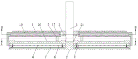
FIG. 1 is a schematic view of the internal structure of the present invention;
FIG. 2 is a schematic view of the structure of the plane A of FIG. 1 according to the present invention;
FIG. 3 is a schematic view of the structure of the plane B of FIG. 1 according to the present invention;
fig. 4 is an enlarged view of fig. 1 at C.
Reference numbers in the figures: 1. a column; 2. a base plate; 3. a fixing plate; 4. a movable plate; 5. a vertical rod; 6. a groove; 7. a flat plate; 8. a transverse plate; 9. a threaded hole; 10. a threaded rod; 11. a rotating wheel; 12. an arc-shaped slot; 13. a movable block; 14. a round bar; 15. a third chute; 16. a third slider; 17. a first chute; 18. a first slider; 19. a second chute; 20. an arc-shaped groove; 21. and a fourth chute.
Detailed Description
The technical solutions in the embodiments of the present invention will be described clearly and completely with reference to the accompanying drawings in the embodiments of the present invention, and it is obvious that the described embodiments are only some embodiments of the present invention, not all embodiments. Based on the embodiments in the present invention, all other embodiments obtained by a person skilled in the art without creative work belong to the protection scope of the present invention.
Referring to fig. 1-4, the present invention provides a technical solution: an adjustable crane base comprises an upright post 1, a bottom plate 2 is arranged at the lower side of the upright post 1, the bottom end of the upright post 1 is movably connected with the top surface center of the bottom plate 2, a fourth chute 21 is arranged at the top surface center of the bottom plate 2, the bottom end of the upright post 1 is inserted into the fourth chute 21, the upright post 1 is movably connected with the fourth chute 21, four fixed plates 3 are uniformly distributed and fixedly connected with the side wall of the upright post 1, a movable plate 4 is movably connected with the bottom surface of the fixed plate 3, the movable plate 4 is arranged in an L shape, a first chute 17 is arranged on the bottom surface of the fixed plate 3, a first sliding block 18 is fixedly connected with the side of the front side wall and the rear side wall of the first chute 17 far away from the upright post 1, second chutes 19 are respectively arranged on the front side wall and the rear side wall of the movable plate 4, the first sliding block 18 is inserted into the second chute, the vertical rod 5 is movably connected with the bottom plate 2, four arc-shaped grooves 20 are uniformly distributed on the bottom surface of the bottom plate 2, one end of the vertical rod 5, which is far away from the movable plate 4, is inserted into the arc-shaped grooves 20, the vertical rod 5 is movably connected with the arc-shaped grooves 20, the flat plate 7 is pulled out through the meshing of the vertical rod 5 and the arc-shaped grooves 20, the supporting area is increased, the stability is improved, four grooves 6 are uniformly distributed on the side wall of the bottom plate 2, the flat plate 7 is arranged in the grooves 6, the transverse plate 8 is arranged on the upper side of the flat plate 7, two threaded holes 9 are symmetrically arranged on the transverse plate 8, a threaded rod 10 is movably connected in the threaded holes 9, the threaded holes 9 extend out from both ends of the threaded rod 10, a rotating wheel 11 is fixedly connected at the top end of, be provided with the movable block 13 in the arc wall 12, fixedly connected with round bar 14 on the movable block 13, lateral wall swing joint around movable block 13 and arc wall 12 is run through at the both ends of round bar 14, the round groove has been seted up on the top surface center of movable block 13, circular shape third spout 15 has been seted up on the lateral wall of round groove, threaded rod 10 is close to fixedly connected with third slider 16 on the lateral wall of bottom, third slider 16 inserts in third spout 15, swing joint between third slider 16 and the third spout 15, the realization is to dull and stereotyped 7 inclination's change, adapt to the difference of topography, make the support more stable, diaphragm 8 keeps away from bottom plate 2 center one side and extends recess 6 and fly leaf 4 fixed connection.
The working principle is as follows: the utility model discloses the device is at first rotated bottom plate 2 when using for the montant 5 of bottom plate 2 upside moves in arc recess 20, drives movable plate 4 through the motion of montant 5 and moves, and first slider 18 moves in second spout 19 on movable plate 4, and movable plate 4 extends fixed plate 3, stimulates diaphragm 8 through fixed plate 3 and moves, makes diaphragm 8 pull out flat plate 7 from recess 6, realizes increasing the function of bottom sprag area; and then according to the inclined shape of the bottom surface, the rotating wheel 11 is rotated, so that the rotating wheel 11 drives the flat plate 7 on the lower side to move, the inclined end angle of the flat plate 7 is adapted to the shape of the bottom surface, and the crane can better play a supporting role.
Although embodiments of the present invention have been shown and described, it will be appreciated by those skilled in the art that changes, modifications, substitutions and alterations can be made in these embodiments without departing from the principles and spirit of the invention, the scope of which is defined in the appended claims and their equivalents.
Claims (5)
1. An adjustable crane base comprising a column (1), characterized in that: the bottom plate (2) is arranged on the lower side of the stand column (1), the bottom end of the stand column (1) is movably connected with the top surface center of the bottom plate (2), four fixing plates (3) are fixedly connected on the side wall of the stand column (1) in an evenly distributed mode, a movable plate (4) is movably connected on the bottom surface of the fixing plates (3), the movable plate (4) is arranged in an L shape, a vertical rod (5) is fixedly connected on one side of the movable plate (4) close to the stand column (1), the vertical rod (5) is movably connected with the bottom plate (2), four grooves (6) are uniformly distributed on the side wall of the bottom plate (2), a flat plate (7) is arranged in each groove (6), a transverse plate (8) is arranged on the upper side of the flat plate (7), two threaded holes (9) are symmetrically formed in the transverse plate (8), and a threaded, threaded holes (9) extend from two ends of the threaded rod (10), a rotating wheel (11) is fixedly connected to the top end of the threaded rod (10), the bottom end of the threaded rod (10) is movably connected with the flat plate (7), and one side, away from the center of the bottom plate (2), of the transverse plate (8) extends out of a groove (6) and is fixedly connected with the movable plate (4).
2. An adjustable crane substructure as claimed in claim 1, wherein: two arc wall (12) have been seted up to the ascending bilateral symmetry of top surface of dull and stereotyped (7), be provided with movable block (13) in arc wall (12), fixedly connected with round bar (14) on movable block (13), lateral wall swing joint around movable block (13) and arc wall (12) is run through at the both ends of round bar (14), the round groove has been seted up on the top surface center of movable block (13), circular shape third spout (15) have been seted up on the lateral wall of round groove, threaded rod (10) are close to fixedly connected with third slider (16) on the lateral wall of bottom, third slider (16) insert in third spout (15), swing joint between third slider (16) and third spout (15).
3. An adjustable crane substructure as claimed in claim 1, wherein: first spout (17) have been seted up on the bottom surface of fixed plate (3), stand (1) one side fixedly connected with first slider (18) is kept away from to the front and back lateral wall of first spout (17), second spout (19) have all been seted up on the front and back lateral wall of fly leaf (4), first slider (18) insert in second spout (19), swing joint between first slider (18) and second spout (19).
4. An adjustable crane substructure as claimed in claim 1, wherein: four arc grooves (20) are uniformly distributed on the bottom surface of the bottom plate (2), one end of the vertical rod (5) far away from the movable plate (4) is inserted into the arc grooves (20), and the vertical rod (5) is movably connected with the arc grooves (20).
5. An adjustable crane substructure as claimed in claim 1, wherein: the top surface center of bottom plate (2) has seted up fourth spout (21), the bottom of stand (1) inserts in fourth spout (21), swing joint between stand (1) and fourth spout (21).
Priority Applications (1)
| Application Number | Priority Date | Filing Date | Title |
|---|---|---|---|
| CN201920640326.9U CN210128186U (en) | 2019-05-07 | 2019-05-07 | Adjustable crane base |
Applications Claiming Priority (1)
| Application Number | Priority Date | Filing Date | Title |
|---|---|---|---|
| CN201920640326.9U CN210128186U (en) | 2019-05-07 | 2019-05-07 | Adjustable crane base |
Publications (1)
| Publication Number | Publication Date |
|---|---|
| CN210128186U true CN210128186U (en) | 2020-03-06 |
Family
ID=69662118
Family Applications (1)
| Application Number | Title | Priority Date | Filing Date |
|---|---|---|---|
| CN201920640326.9U Active CN210128186U (en) | 2019-05-07 | 2019-05-07 | Adjustable crane base |
Country Status (1)
| Country | Link |
|---|---|
| CN (1) | CN210128186U (en) |
Cited By (2)
| Publication number | Priority date | Publication date | Assignee | Title |
|---|---|---|---|---|
| CN112875065A (en) * | 2021-01-13 | 2021-06-01 | 罗颖邱 | Constant-temperature storage method for synthetic PU resin |
| CN113439582A (en) * | 2021-08-06 | 2021-09-28 | 安徽训发农业科技有限公司 | Three-dimensional bowl-type cultivation device and working method thereof |
-
2019
- 2019-05-07 CN CN201920640326.9U patent/CN210128186U/en active Active
Cited By (2)
| Publication number | Priority date | Publication date | Assignee | Title |
|---|---|---|---|---|
| CN112875065A (en) * | 2021-01-13 | 2021-06-01 | 罗颖邱 | Constant-temperature storage method for synthetic PU resin |
| CN113439582A (en) * | 2021-08-06 | 2021-09-28 | 安徽训发农业科技有限公司 | Three-dimensional bowl-type cultivation device and working method thereof |
Similar Documents
| Publication | Publication Date | Title |
|---|---|---|
| CN210128186U (en) | Adjustable crane base | |
| CN211286571U (en) | Energy-conserving steel structure support of high strength | |
| CN205677344U (en) | Electric pole centering guide machine | |
| CN212583205U (en) | Lifting channel steel frame suitable for construction of attached lifting scaffold | |
| CN209817390U (en) | Hanging basket system for inward-inclined wall construction | |
| CN205129715U (en) | Closed assembly platform unshakable in one's determination | |
| CN210988809U (en) | Novel multi-functional electric contest table | |
| CN210152204U (en) | Building scaffold adjusts backup pad | |
| CN212270698U (en) | Bridge construction support bracket | |
| KR101451793B1 (en) | structure of the small crane lock | |
| CN207090791U (en) | One kind lifting parallel shelf | |
| CN206858045U (en) | A kind of jack supporting piece of convenient regulation | |
| CN205076241U (en) | Glass all revolving racks of casing | |
| CN201566052U (en) | Machine body of hole drilling machine | |
| CN204566377U (en) | A kind of precast beam steel strand pulling machine hoisting frame device | |
| CN217229926U (en) | Tensile hanging flower basket that building engineering used | |
| CN218261701U (en) | Stable good crane base | |
| CN215208258U (en) | Higher material lifting device for building decoration of security | |
| CN217297077U (en) | Supporting leg column for crane operation | |
| CN218563019U (en) | A template subassembly for clear water concrete construction | |
| CN218424795U (en) | Belt cleaning device is used in roll production | |
| CN216040637U (en) | Height-adjustable high-stability bridge rubber support | |
| CN212249074U (en) | Can dismantle simple and easy side slope drilling platform | |
| CN217972263U (en) | Novel beam lifter structure | |
| CN218341373U (en) | Bridge crane single-beam groove-to-groove welding machine frame |
Legal Events
| Date | Code | Title | Description |
|---|---|---|---|
| GR01 | Patent grant | ||
| GR01 | Patent grant | ||
| TR01 | Transfer of patent right | ||
| TR01 | Transfer of patent right |
Effective date of registration: 20221107 Address after: Room 136, No. 189, South Bamboo Road, Xinchang Town, Pudong New Area, Shanghai, 200135 Patentee after: Guanzhe Machinery (Shanghai) Co.,Ltd. Address before: 362000 Xiaguang No. 21, Xiamei village, Xiamei Town, Nan'an City, Quanzhou City, Fujian Province Patentee before: NAN'AN TAOZHIRAN BUILDING MATERIAL CO.,LTD. |