CN210068597U - Hydraulic system of hydraulic pumping unit - Google Patents
Hydraulic system of hydraulic pumping unit Download PDFInfo
- Publication number
- CN210068597U CN210068597U CN201920387412.3U CN201920387412U CN210068597U CN 210068597 U CN210068597 U CN 210068597U CN 201920387412 U CN201920387412 U CN 201920387412U CN 210068597 U CN210068597 U CN 210068597U
- Authority
- CN
- China
- Prior art keywords
- ball valve
- hydraulic
- opening
- valve
- oil
- Prior art date
- Legal status (The legal status is an assumption and is not a legal conclusion. Google has not performed a legal analysis and makes no representation as to the accuracy of the status listed.)
- Active
Links
Images

Abstract
The application discloses hydraulic pumping unit hydraulic system, this system includes: a base element, a first difference element, a second difference element, a first opening and closing system conversion ball valve (21) and a second opening and closing system conversion ball valve (26), wherein the base element is connected with the first difference element through the first opening and closing system conversion ball valve (21), and the base element is connected with the second difference element through the second opening and closing system conversion ball valve (26); when the first switching ball valve (21) of the opening and closing system is opened and the second switching ball valve (26) of the opening and closing system is closed, the hydraulic system of the hydraulic pumping unit operates in an open system; when the first switching ball valve (21) is closed and the second switching ball valve (26) is opened, the hydraulic system of the hydraulic pumping unit operates in a closed system. This application can avoid oil well oil recovery process to interrupt, promotes hydraulic pumping unit hydraulic system's work efficiency.
Description
Technical Field
The application relates to the technical field of oil extraction, in particular to a hydraulic system of a hydraulic pumping unit.
Background
According to the circulation mode of oil liquid, the hydraulic system of the pumping unit with one station and two wells can be divided into an open system and a closed system. The open system utilizes an energy accumulator, a hydraulic motor and the like to recycle the energy of the lower stroke of the oil cylinder; the closed system can directly pressurize oil from the down stroke oil cylinder entering a suction inlet of the oil pump, and direct recycling of the down stroke energy of the oil cylinder is achieved.
Compared with an open system, the closed system can directly recycle the down stroke energy of the oil cylinder, the energy utilization rate is high, and the oil inlet and the oil outlet amount of the up-and-down stroke oil cylinder are required to be the same. This can be realized in the well selection stage, but along with the development of the oil field, the liquid supply capacity of the oil well changes, and the hydraulic oil discharged by the downward oil cylinder is more than or less than the hydraulic oil required by the upward oil cylinder, so that the working parameters of the oil well change, and the service conditions of a closed system are damaged. Under the condition, or oil wells with similar liquid production rates are selected again for re-pairing, and a closed system is continuously adopted for the oil wells; or to convert a closed system to an open system. The oil extraction process of the oil well can be interrupted undoubtedly by the two processing modes, and the working efficiency of the hydraulic system of the hydraulic pumping unit is reduced.
SUMMERY OF THE UTILITY MODEL
The embodiment of the application provides a hydraulic pumping unit hydraulic system for avoid oil well oil recovery process to interrupt, promote hydraulic pumping unit hydraulic system's work efficiency, this system includes:
a base element, a first differential element, a second differential element, a first opening/closing system switching ball valve 21, and a second opening/closing system switching ball valve 26, the base element being connected to the first differential element through the first opening/closing system switching ball valve 21, the base element being connected to the second differential element through the second opening/closing system switching ball valve 26; the base element is an element which is commonly included by the open system and the closed system, the first difference element is an element except the base element in the elements included by the open system, and the second difference element is an element except the base element in the elements included by the closed system; when the first switching ball valve 21 is opened and the second switching ball valve 26 is closed, the hydraulic system of the hydraulic pumping unit operates as an open system; when the first opening and closing system changeover ball valve 21 is closed and the second opening and closing system changeover ball valve 26 is opened, the hydraulic system of the hydraulic pumping unit operates in a closed system.
In the embodiment of the application, the hydraulic system of the hydraulic pumping unit comprises an element of an open system and an element of a closed system, and the open system and the closed system are converted through a first switching system conversion ball valve and a second switching system conversion ball valve. Therefore, when the oil inlet and the oil outlet of the oil cylinders in the up and down strokes are the same, the hydraulic system of the hydraulic oil pumping unit can be connected into a closed system, so that the energy utilization rate of the system is improved; when the oil feeding amount and the oil discharging amount of the up-stroke and down-stroke oil cylinders are different, the hydraulic system of the hydraulic pumping unit can be connected into an open system on the premise of not interrupting the oil extraction process, the working efficiency of the hydraulic system of the hydraulic pumping unit is improved, and meanwhile the universality of the hydraulic system of the hydraulic pumping unit is also improved.
Drawings
In order to more clearly illustrate the embodiments of the present application or the technical solutions in the prior art, the drawings used in the description of the embodiments or the prior art will be briefly described below, it is obvious that the drawings in the following description are only some embodiments of the present application, and for those skilled in the art, other drawings can be obtained according to the drawings without creative efforts. In the drawings:
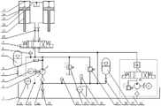
fig. 1 is a structural diagram of a hydraulic system of a hydraulic pumping unit provided in an embodiment of the present application;
FIG. 2 is a block diagram of an open system provided in an embodiment of the present application;
fig. 3 is a structural diagram of a closed system provided in an embodiment of the present application.
Reference numerals
1: an oil tank 2: liquid motor
3: variable hydraulic oil pump 4: electric machine
5: high-pressure accumulator ball valve 6: high pressure transmitter
7: high-pressure accumulator 8: high pressure gauge
9: electromagnetic directional valve 10: main unit ball valve
11: piston rod 12: recovery oil pipe
13: the oil cylinder 14: piston
15: the displacement sensor 16: liquid level transducer
17: the temperature transmitter 18: oil filter
19: the check valve 20: one-way clutch
21: first opening/closing system switching ball valve 22: low pressure gauge
23: safety valve 24: cooling device
25: low pressure transmitter 26: second opening and closing system conversion ball valve
27: relief valve 28: low-pressure accumulator ball valve
29: low-pressure accumulator 30: liquid supplementing module of closed system
Detailed Description
To make the objects, technical solutions and advantages of the embodiments of the present application more apparent, the embodiments of the present application are further described in detail below with reference to the accompanying drawings. The exemplary embodiments and descriptions of the present application are provided herein to explain the present application and not to limit the present application.
The embodiment of the application provides a hydraulic system of a hydraulic pumping unit, and as shown in fig. 1, the system comprises a base element, a first difference element, a second difference element, a first opening and closing system switching ball valve 21 and a second opening and closing system switching ball valve 26.
The basic element is an element which is commonly included by the open system and the closed system, the first difference element is an element except the basic element in the elements included by the open system, and the second difference element is an element except the basic element in the elements included by the closed system. The first opening/closing system switching ball valve 21 and the second opening/closing system switching ball valve 26 are shut valves, and have two states of on and off.
The base element is connected to the first differential element through a first opening/closing system switching ball valve 21, and the base element is connected to the second differential element through a second opening/closing system switching ball valve 26. Referring to fig. 1 and 2, when the first switching ball valve 21 is opened and the second switching ball valve 26 is closed, the hydraulic system of the hydraulic pumping unit operates as an open system as shown in fig. 2; referring to fig. 1 and 3, when the first switching ball valve 21 is closed and the second switching ball valve 26 is opened, the hydraulic system of the hydraulic pumping unit operates as a closed system as shown in fig. 3.
The basic elements comprise an oil tank 1, a variable hydraulic oil pump 3, a motor 4, a high-pressure accumulator ball valve 5, a high-pressure transmitter 6, a high-pressure accumulator 7, a high-pressure gauge 8, an electromagnetic directional valve 9, a main engine ball valve 10, a piston rod 11, a recovered oil pipe 12, an oil cylinder 13, a piston 14, a displacement sensor 15, a liquid level transmitter 16, a temperature transmitter 17, an oil filter 18, a check valve 19, a low-pressure gauge 22, a safety valve 23, a cooler 24, a low-pressure transmitter 25 and an overflow valve 27.
Referring to fig. 1, a displacement sensor 15, a piston 14 and a piston rod 11 are disposed inside an oil cylinder 13, the displacement sensor 15 is disposed on an inner wall of the oil cylinder 13 and connected to one end of the piston 14, and the other end of the piston 14 is connected to the piston rod 11. The two oil cylinders 13 are connected through a recovery oil pipe 12 and are respectively connected with one end of the electromagnetic directional valve 9 through a main engine ball valve 10. The other end of the electromagnetic directional valve 9 is simultaneously connected with a high-pressure gauge 8, a high-pressure accumulator ball valve 5, a high-pressure transmitter 6, a variable hydraulic oil pump 3, a safety valve 23 and an overflow valve 27. The other end of the high-pressure accumulator ball valve 5 is connected with a high-pressure accumulator 7. The variable displacement hydraulic oil pump 3 is also connected to both the motor 4 and the oil filter 18. The oil filter 18 is also connected to a check valve 19, a low pressure gauge 22, a low pressure transmitter 25 and an overflow valve 27. Wherein the non-return valve 19 extends into the interior of the fuel tank 1. A level transmitter 16, a temperature transmitter 17 and a cooler 24 are also arranged in the fuel tank 1.
The first difference element comprises a liquid motor 2. The first opening/closing system switching ball valve 21 is provided between the electromagnetic directional valve 9 and the liquid motor 2, and the electromagnetic directional valve 9 is connected to one end of the liquid motor 2 through the first opening/closing system switching ball valve 21. The other end of the liquid motor 2 is connected with the oil tank 1.
Furthermore, the first difference element further comprises: and a one-way clutch 20.
When the hydraulic system of the hydraulic pumping unit operates as an open system, the hydraulic oil discharged from the lower stroke oil cylinder 13 drives the hydraulic motor 2 to work and then is discharged back to the oil tank 1, so that the hydraulic energy is converted into the mechanical energy of the hydraulic motor 2. The hydraulic motor 2 assists the motor 4 to drive the variable hydraulic oil pump 3, and when the hydraulic motor 2 works, the variable hydraulic oil pump 3 is driven to rotate by the one-way clutch 20. When the hydraulic system of the hydraulic pumping unit operates in a closed system, the hydraulic motor 2 does not work, and at the moment, the motor 4 drives the variable hydraulic oil pump 3 to rotate, but cannot drive the variable hydraulic oil pump 3 to rotate through the one-way clutch 20.
The second difference element comprises a low-pressure accumulator 29 and a closed-system fluid replacement module 30. The second switching system conversion ball valve 26 is arranged between the electromagnetic directional valve 9 and the closed system liquid supplementing module 30 and between the electromagnetic directional valve 9 and the low-pressure energy accumulator 29, and the electromagnetic directional valve 9 is respectively connected with one end of the closed system liquid supplementing module 30 and the low-pressure energy accumulator 29 through the second switching system conversion ball valve 26. The other end of the closed system liquid supplementing module 30 is connected with the oil tank 1.
In addition, the second differential element comprises a low-pressure accumulator ball valve 28, and the second opening/closing system changeover ball valve 26 is connected with a low-pressure accumulator 29 through the low-pressure accumulator ball valve 28.
When the closed system operates, the low-pressure accumulator 29 is used for maintaining the pressure stability of the low-pressure system, and the closed system fluid infusion module 30 compensates hydraulic oil leaked by the system.
When the hydraulic system of the hydraulic pumping unit operates in a closed system, the hydraulic oil discharged from the down oil cylinder 13 directly enters the variable hydraulic oil pump 3, and is pressurized by the variable hydraulic oil pump 3 to drive the other oil cylinder 13 to perform an upper stroke. Because the hydraulic oil at the inlet of the variable hydraulic oil pump 3 has certain pressure, the energy transmitted to the hydraulic oil by the variable hydraulic oil pump 3 is correspondingly reduced, and the recycling rate of the energy is improved.
It is to be added that when only one well of a pair of wells is working, the high pressure accumulator 7 can be used instead of the non-working well, so that the hydraulic system of the hydraulic pumping unit still works according to the working principle of the pair of wells by using an open system or a closed system.
In the embodiment of the application, the hydraulic system of the hydraulic pumping unit comprises an element of an open system and an element of a closed system, and the open system and the closed system are converted through a first switching system conversion ball valve and a second switching system conversion ball valve. Therefore, when the oil inlet and the oil outlet of the oil cylinders in the up and down strokes are the same, the hydraulic system of the hydraulic oil pumping unit can be connected into a closed system, so that the energy utilization rate of the system is improved; when the oil feeding amount and the oil discharging amount of the up-stroke and down-stroke oil cylinders are different, the hydraulic system of the hydraulic pumping unit can be connected into an open system on the premise of not interrupting the oil extraction process, the working efficiency of the hydraulic system of the hydraulic pumping unit is improved, and meanwhile the universality of the hydraulic system of the hydraulic pumping unit is also improved.
The above-mentioned embodiments are further described in detail for the purpose of illustrating the invention, and it should be understood that the above-mentioned embodiments are only illustrative of the present invention and are not intended to limit the scope of the present invention, and any modifications, equivalent substitutions, improvements, etc. made within the spirit and principle of the present invention should be included in the scope of the present invention.
Claims (10)
1. A hydraulic system for a hydraulic pumping unit, the system comprising:
a base element, a first difference element, a second difference element, a first opening and closing system conversion ball valve (21) and a second opening and closing system conversion ball valve (26), wherein the base element is connected with the first difference element through the first opening and closing system conversion ball valve (21), and the base element is connected with the second difference element through the second opening and closing system conversion ball valve (26); the base element is an element which is commonly included by the open system and the closed system, the first difference element is an element except the base element in the elements included by the open system, and the second difference element is an element except the base element in the elements included by the closed system;
when the first switching ball valve (21) of the opening and closing system is opened and the second switching ball valve (26) of the opening and closing system is closed, the hydraulic system of the hydraulic pumping unit operates in an open system; when the first switching ball valve (21) is closed and the second switching ball valve (26) is opened, the hydraulic system of the hydraulic pumping unit operates in a closed system.
2. The system of claim 1, wherein the base element comprises:
the hydraulic oil recovery system comprises an oil tank (1), a variable hydraulic oil pump (3), a motor (4), a high-pressure energy accumulator ball valve (5), a high-pressure transmitter (6), a high-pressure energy accumulator (7), a high-pressure gauge (8), an electromagnetic directional valve (9), a main machine ball valve (10), a piston rod (11), a recovered oil pipe (12), an oil cylinder (13), a piston (14), a displacement sensor (15), a liquid level transmitter (16), a temperature transmitter (17), an oil filter (18), a check valve (19), a low-pressure gauge (22), a safety valve (23), a cooler (24), a low-pressure transmitter (25) and an overflow valve (.
3. The system of claim 2, wherein the first difference element comprises: a liquid motor (2).
4. A system according to claim 3, characterized in that a first switching ball valve (21) is arranged between the electromagnetic directional valve (9) and the hydraulic motor (2), the electromagnetic directional valve (9) being connected to one end of the hydraulic motor (2) via the first switching ball valve (21).
5. System according to claim 4, characterized in that the other end of the hydraulic motor (2) is connected to the oil tank (1).
6. The system of claim 3, wherein the first difference element further comprises: a one-way clutch (20).
7. The system of claim 2, wherein the second difference element comprises: a low-pressure accumulator (29) and a closed system liquid supplementing module (30).
8. The system according to claim 7, characterized in that a second switching ball valve (26) is arranged between the electromagnetic directional valve (9) and the closed system fluid replenishing module (30) and the low pressure accumulator (29), and the electromagnetic directional valve (9) is respectively connected with one end of the closed system fluid replenishing module (30) and the low pressure accumulator (29) through the second switching ball valve (26).
9. The system according to claim 8, characterized in that the other end of the closed system fluid replacement module (30) is connected to the tank (1).
10. System according to claim 8, characterized in that said second differential element further comprises a low-pressure accumulator ball valve (28), said second opening and closing system switching ball valve (26) being connected with said low-pressure accumulator (29) through a low-pressure accumulator ball valve (28).
Priority Applications (1)
| Application Number | Priority Date | Filing Date | Title |
|---|---|---|---|
| CN201920387412.3U CN210068597U (en) | 2019-03-26 | 2019-03-26 | Hydraulic system of hydraulic pumping unit |
Applications Claiming Priority (1)
| Application Number | Priority Date | Filing Date | Title |
|---|---|---|---|
| CN201920387412.3U CN210068597U (en) | 2019-03-26 | 2019-03-26 | Hydraulic system of hydraulic pumping unit |
Publications (1)
| Publication Number | Publication Date |
|---|---|
| CN210068597U true CN210068597U (en) | 2020-02-14 |
Family
ID=69434525
Family Applications (1)
| Application Number | Title | Priority Date | Filing Date |
|---|---|---|---|
| CN201920387412.3U Active CN210068597U (en) | 2019-03-26 | 2019-03-26 | Hydraulic system of hydraulic pumping unit |
Country Status (1)
| Country | Link |
|---|---|
| CN (1) | CN210068597U (en) |
-
2019
- 2019-03-26 CN CN201920387412.3U patent/CN210068597U/en active Active
Similar Documents
| Publication | Publication Date | Title |
|---|---|---|
| US20220412196A1 (en) | Heavy Oil Lifting Device and Heavy Oil Lifting Method | |
| RU52125U1 (en) | ELECTRIC HYDRAULIC DRIVE PUMP UNIT | |
| CN201241806Y (en) | Hydraulic gas compressor | |
| CN107013535B (en) | A kind of pressure Self Matching energy utility system | |
| CN202926293U (en) | Fully-automatic hydraulic oil pumping machine | |
| CN210068597U (en) | Hydraulic system of hydraulic pumping unit | |
| CN206830551U (en) | Pumping unit hydraulic system | |
| CN201836284U (en) | Energy-collecting shock absorber | |
| CN206091936U (en) | Oil well casing gas pressure boost recovery unit | |
| CN216111151U (en) | Motor direct-drive fracturing device | |
| CN203702099U (en) | Automatic reversing locked hydraulic driving rod-less oil extraction device | |
| CN2849265Y (en) | Small size hydraulic pump station | |
| CN201202614Y (en) | Energy-saving movable pumping station | |
| CN210290030U (en) | Auxiliary liquid drainage device for natural gas well | |
| CN2433411Y (en) | Crank connecting rod type plunger mud pump | |
| CN205370884U (en) | Many hydraulic cylinders of plunger type combination slush pump | |
| CN204827842U (en) | Free piston fracturing pump and fracturing unit car | |
| CN112145130B (en) | Pairing method and device for oil wells of hydraulic pumping unit | |
| CN201152238Y (en) | Plunger type water pump | |
| CN202971147U (en) | Oil leakage type deep pumping and deloading device | |
| CN209385440U (en) | A kind of hydraulic assembly structure and hydraulic pressure drive injection device | |
| CN219888030U (en) | Hydraulic plunger water injection device | |
| CN107191160B (en) | Double-plunger submersible diaphragm pump system and relay lifting method thereof | |
| CN201132372Y (en) | Rubber vulcanizing press with combined hydrocylinder | |
| CN205078410U (en) | Two effect hydraulic piston pumps |
Legal Events
| Date | Code | Title | Description |
|---|---|---|---|
| GR01 | Patent grant | ||
| GR01 | Patent grant |