Multi-azimuth oscillating fan
Technical Field
The utility model relates to a fan, especially a diversified fan of shaking the head.
Background
Chinese patent No. CN 201320844390.1 discloses a fan oscillating structure and an electric fan with the same in 2014, 6-25. Should shake the head structure and include: a motor housing; a fixing plate fixed in the motor case; the first motor is positioned in the motor shell and fixed on the fixing plate, and an output shaft of the first motor extends outwards from the inside of the motor shell so as to be suitable for being connected with fan blades; the upper end of the upright post pipe extends into the motor shell; the rotating shaft penetrates through the fixing plate and is connected with the upper end of the upright tube through the transverse torque hinge, so that the inclination angle of the first motor relative to the upright tube is adjustable; and the second motor is positioned in the motor shell and is fixed on the fixing plate so as to drive the first motor to swing around the central axis of the rotating shaft. This structure can only fix a position and shake the head and blow, can not satisfy and diversely shake the head and blow, consequently, the coverage area that the fan was bloied is not wide.
Disclosure of Invention
An object of the utility model is to overcome the not enough of above-mentioned prior art existence, and provide a simple structure, reasonable, fan motor can control the shake head and blow, and simultaneously, fan motor also can shake the head from top to bottom and blow, reaches the diversified fan of shaking the head of and blowing, improves the diversified fan of shaking the head of the coverage area that the fan was blown.
The purpose of the utility model is realized like this:
the utility model provides a diversified fan of shaking head, includes the aircraft nose assembly, and the aircraft nose assembly includes fan motor, connector and controls the actuating mechanism that shakes head, and fan motor shakes head actuating mechanism and is connected its characterized in that with the connector through controlling: the fan motor swings up and down and is arranged on the left-right oscillating driving mechanism, the fan motor driving mechanism also comprises an upper-lower oscillating driving mechanism, and the upper-lower oscillating driving mechanism is connected between the fan motor and the left-right oscillating driving mechanism.
The purpose of the utility model can also adopt the following technical measures to solve:
as a more specific scheme, the up-and-down shaking head driving mechanism comprises an up-and-down shaking head bracket, an up-and-down shaking head motor, a first crank and a first connecting rod; the upper and lower support of shaking the head sets up on fan motor, and the motor setting of shaking the head from top to bottom is on the support of shaking the head from top to bottom, and the pivot and the one end fixed connection of first articulate of the motor of shaking the head from top to bottom, the other end of first articulate rotates with the one end of first connecting rod to be connected, and the other end of first connecting rod rotates with the actuating mechanism that shakes the head from left to right to be connected.
As a further scheme, the left-right oscillating driving mechanism comprises a left-right oscillating support, a positioning sleeve, a left-right oscillating motor, a second crank and a second connecting rod; fan motor sways from top to bottom and sets up on the support of shaking the head about, and the position sleeve rotates and sets up on the connector, and the support of shaking the head about is connected with the position sleeve, and the position sleeve is equipped with eccentric fulcrum, and the motor of shaking the head about sets up on the support of shaking the head about, and the pivot and the one end fixed connection of second crank of the motor of shaking the head about, the articulate other end of second and the one end of second connecting rod rotate to be connected, and the other end of second connecting rod rotates with the eccentric fulcrum of position sleeve to be connected.
As a further scheme, the left-right oscillating support comprises a bottom plate, a first up-down oscillating support arm, a second up-down oscillating support arm and a vertical shaft, the first up-down oscillating support arm is arranged on the left side and the right side of the top surface of the bottom plate, the second up-down oscillating support arm is arranged on the top surface of the bottom plate and is positioned behind the first up-down oscillating support arm, the vertical shaft is arranged at the bottom of the bottom plate, and the left-right oscillating motor is arranged at the top of the bottom plate; the fan motor is connected with the first up-and-down oscillating support arm in an up-and-down oscillating mode, and the other end of the first connecting rod is rotatably connected with the second up-and-down oscillating support arm; the vertical shaft is connected with the positioning sleeve, the connecting head is provided with a sleeve hole corresponding to the positioning sleeve, and the positioning sleeve is inserted into the sleeve hole and is in running fit with the sleeve hole.
As a further scheme, the machine head assembly further comprises an inner shell, the inner shell is arranged outside the fan motor, the fan motor is connected with the first up-down shaking head support arm in an up-down shaking mode through the inner shell, and the up-down shaking head support is fixedly connected with the inner shell.
As a further scheme, the inner shell comprises an inner front shell and an inner rear shell, the inner front shell is plate-shaped, the inner rear shell is cover-shaped, the fan motor is packaged in the inner rear shell through the inner front shell, and a rotating shaft of the fan motor extends out of the inner front shell.
As a further scheme, the machine head assembly further comprises an outer shell, and the inner shell, the fan motor, the driving mechanism capable of shaking the head up and down and the driving mechanism capable of shaking the head left and right are all arranged in the outer shell.
As a further scheme, the outer shell comprises an outer front shell, an outer rear shell and an outer bottom shell, the outer front shell is plate-shaped, the outer rear shell is cover-shaped, the outer bottom shell is boat-shaped, the outer front shell of the outer shell is connected with the inner front shell of the inner shell, the outer rear shell of the outer shell is fixedly connected with the up-and-down shaking bracket, and the outer bottom shell is connected with the left-and-right shaking bracket in a matching manner.
As a further scheme, the support of shaking the head from top to bottom includes inner shell connector and outer casing connector, and the inner shell connector setting is shaking the head from top to bottom support front end and be connected with the interior backshell rear end of inner shell, and the outer casing connector setting is shaking the head from top to bottom support rear end and with the outer backshell fixed connection of shell.
As a further scheme, the fan device further comprises a fan mesh enclosure, fan blades, a telescopic upright post and a base, wherein the telescopic upright post is arranged on the base, the connector is arranged at the upper end of the telescopic upright post, the machine head assembly is arranged on the connector, and the fan blades are connected with a rotating shaft of a fan motor on the machine head assembly; the fan mesh enclosure surrounds the fan blades and is connected with the front end of the shell of the machine head assembly.
The utility model has the advantages as follows:
the multi-azimuth oscillating fan can oscillate left and right under the control of the left-right oscillating driving mechanism, and in addition, the up-down oscillating driving mechanism can also control or independently control the fan motor to oscillate up and down relative to the left-right oscillating driving mechanism, so that multi-azimuth oscillating and blowing are realized; when the left-right and up-down oscillating driving mechanisms work simultaneously, 8-shaped movement of the fan motor can be realized, so that air can be blown in multiple directions.
Drawings
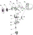
Fig. 1 is a schematic view of an overall component decomposition structure of a handpiece according to an embodiment of the present invention.
Fig. 2 is a schematic structural view of fig. 1 without the housing.
Fig. 3 is a schematic diagram of the structure of the middle head assembly taken away from the rear housing of the utility model.
Fig. 4 is a side view of the structure of fig. 3.
Fig. 5 is a schematic top view of fig. 3.
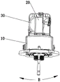
Fig. 6 is a schematic view of the whole structure of the present invention.
In the figure:
10 is a machine head assembly, 1 is a fan motor, 21 is an inner front shell, 22 is an inner rear shell, 31 is an outer front shell, 32 is an outer rear shell, 33 is an outer bottom shell, 20 is an up-down oscillating driving mechanism, 4 is an up-down oscillating motor, 41 is a first crank, 42 is a first connecting rod, 5 is an up-down oscillating bracket, 51 is an inner shell connector, 52 is an outer shell connector, 30 is a left-right oscillating driving mechanism, 6 is a left-right oscillating motor, 61 is a second crank, 62 is a second connecting rod, 7 is a left-right oscillating bracket, 71 is a first up-down oscillating support arm, 72 is a bottom plate, 73 is a vertical shaft, 74 is a second up-down oscillating support arm, 8 is a positioning sleeve, 81 is an eccentric fulcrum, 9 is a connector, and 91 is a sleeve hole;
40 is a fan blade;
50 is a fan guard;
60 is a telescopic upright post;
70 is a base.
Detailed Description
The invention will be further described with reference to the following drawings and examples:
the utility model provides a fan of shaking head in diversified, includes aircraft nose assembly 10, and aircraft nose assembly 10 includes fan motor 1, connector 9 and controls actuating mechanism 30 of shaking head, and fan motor 1 is connected with connector 9 through controlling actuating mechanism 30 of shaking head, fan motor 1 sways the setting from top to bottom on controlling actuating mechanism 30 of shaking head, still includes actuating mechanism 20 of shaking head from top to bottom, and actuating mechanism 20 of shaking head from top to bottom is connected between fan motor 1 and control actuating mechanism 30 of shaking head.
The up-and-down shaking head driving mechanism 20 comprises an up-and-down shaking head bracket 5, an up-and-down shaking head motor 4, a first crank 41 and a first connecting rod 42; the upper and lower oscillating support 5 is arranged on the fan motor 1, the upper and lower oscillating motor 4 is arranged on the upper and lower oscillating support 5, a rotating shaft of the upper and lower oscillating motor 4 is fixedly connected with one end of a first crank 41, the other end of the first crank 41 is rotatably connected with one end of a first connecting rod 42, and the other end of the first connecting rod 42 is rotatably connected with the left and right oscillating driving mechanism 30.
The left-right oscillating driving mechanism 30 comprises a left-right oscillating bracket 7, a positioning sleeve 8, a left-right oscillating motor 6, a second crank 61 and a second connecting rod 62; fan motor 1 sways from top to bottom and sets up on the support 7 of shaking the head about, position sleeve 8 rotates and sets up on connector 9, the support 7 of shaking the head about is connected with position sleeve 8, position sleeve 8 is equipped with eccentric fulcrum 81, it sets up on the support 7 of shaking the head about to shake motor 6, the pivot of the motor 6 of shaking the head about and one end fixed connection of second crank 61, the other end of second crank 61 rotates with the one end of second connecting rod 62 to be connected, the other end of second connecting rod 62 rotates with eccentric fulcrum 81 of position sleeve 8 to be connected.
The left-right shaking head bracket 7 comprises a bottom plate 72, a first up-down shaking head support arm 71, a second up-down shaking head support arm 74 and a vertical shaft 73, wherein the first up-down shaking head support arm 71 is arranged on the left side and the right side of the top surface of the bottom plate 72, the second up-down shaking head support arm 74 is arranged on the top surface of the bottom plate 72 and is positioned behind the first up-down shaking head support arm 71, the vertical shaft 73 is arranged at the bottom of the bottom plate 72, and the left-right shaking head motor 6 is arranged at the top of the bottom plate 72; the fan motor 1 is connected with a first up-and-down shaking head support arm 71 in an up-and-down shaking way, and the other end of the first connecting rod 42 is rotationally connected with a second up-and-down shaking head support arm 74; the vertical shaft 73 is connected with the positioning sleeve 8, the connector 9 is provided with a sleeve hole 91 corresponding to the positioning sleeve 8, and the positioning sleeve 8 is inserted into the sleeve hole 91 and is in running fit with the sleeve hole 91.
The head assembly 10 further comprises an inner shell, the inner shell is arranged outside the fan motor 1, the fan motor 1 swings up and down with the first swing support arm 71 through the inner shell, and the swing support 5 is fixedly connected with the inner shell.
The inner shell comprises an inner front shell 21 and an inner rear shell 22, the inner front shell 21 is plate-shaped, the inner rear shell 22 is cover-shaped, the fan motor is packaged in the inner rear shell 22 through the inner front shell 21, and the rotating shaft of the fan motor 1 extends out of the inner front shell 21.
The head assembly 10 further comprises an outer shell, and the inner shell, the fan motor 1, the upper and lower oscillating driving mechanism 20 and the left and right oscillating driving mechanism 30 are all arranged in the outer shell.
The shell includes outer preceding shell 31, outer backshell 32 and outer bottom shell 33, and outer preceding shell 31 is platelike, and outer backshell 32 is the cover form, and outer bottom shell 33 is the ship form, and outer preceding shell 31 of shell is connected with the interior preceding shell 21 of inner shell, the outer backshell 32 and the support 5 fixed connection of shaking the head from top to bottom of shell, outer bottom shell 33 with control the support 7 cooperation of shaking the head and be connected.
The upper and lower support 5 of shaking the head includes inner shell connector 51 and outer casing connector 52, and inner shell connector 51 sets up and shakes the head support 5 front end from top to bottom and is connected with the interior backshell 22 rear end of inner shell, and outer casing connector 52 sets up and shakes the head support 5 rear end from top to bottom and with the outer backshell 32 fixed connection of shell.
The multi-azimuth oscillating fan further comprises a fan mesh enclosure 50, fan blades 40, a telescopic upright post 60 and a base 70, wherein the telescopic upright post 60 is arranged on the base 70, the connector 9 is arranged at the upper end of the telescopic upright post 60, the head assembly 10 is arranged on the connector 9, and the fan blades 40 are connected with a rotating shaft of a fan motor 1 on the head assembly 10; the fan guard 50 surrounds the fan blades 40 and is connected to the front end of the housing of the head assembly 10.
The working principle is as follows: when the up-and-down shaking head driving mechanism 20 is started, the fan motor 1 swings up and down along the arrow A direction in fig. 4; when the left-right oscillating drive mechanism 30 is started, the fan motor 1 swings left and right in the direction of arrow B in fig. 5; when the up-down shaking drive mechanism 20 and the left-right shaking drive mechanism 30 are simultaneously activated, the fan motor 1 roughly swings in an "8" shaped trajectory.