CN210049614U - Auxiliary device for mounting assembly type superposed beam plate - Google Patents
Auxiliary device for mounting assembly type superposed beam plate Download PDFInfo
- Publication number
- CN210049614U CN210049614U CN201920186288.4U CN201920186288U CN210049614U CN 210049614 U CN210049614 U CN 210049614U CN 201920186288 U CN201920186288 U CN 201920186288U CN 210049614 U CN210049614 U CN 210049614U
- Authority
- CN
- China
- Prior art keywords
- slab
- composite
- superposed
- steel bars
- stirrup
- Prior art date
- Legal status (The legal status is an assumption and is not a legal conclusion. Google has not performed a legal analysis and makes no representation as to the accuracy of the status listed.)
- Expired - Fee Related
Links
- 238000009434 installation Methods 0.000 claims abstract description 14
- 239000010959 steel Substances 0.000 claims description 64
- 229910000831 Steel Inorganic materials 0.000 claims description 60
- 239000002131 composite material Substances 0.000 claims description 37
- 239000004567 concrete Substances 0.000 claims description 21
- 230000000149 penetrating effect Effects 0.000 claims description 9
- 238000009417 prefabrication Methods 0.000 claims description 5
- 229910001294 Reinforcing steel Inorganic materials 0.000 claims description 4
- 238000010276 construction Methods 0.000 abstract description 21
- 230000002349 favourable effect Effects 0.000 abstract description 2
- 229910000838 Al alloy Inorganic materials 0.000 description 11
- 230000003014 reinforcing effect Effects 0.000 description 10
- 238000007796 conventional method Methods 0.000 description 8
- 230000002787 reinforcement Effects 0.000 description 7
- 238000007789 sealing Methods 0.000 description 5
- 238000003466 welding Methods 0.000 description 5
- 229910000851 Alloy steel Inorganic materials 0.000 description 4
- XEEYBQQBJWHFJM-UHFFFAOYSA-N Iron Chemical compound [Fe] XEEYBQQBJWHFJM-UHFFFAOYSA-N 0.000 description 4
- 238000004519 manufacturing process Methods 0.000 description 4
- 238000000034 method Methods 0.000 description 4
- 239000011150 reinforced concrete Substances 0.000 description 4
- 229910000746 Structural steel Inorganic materials 0.000 description 2
- 230000006378 damage Effects 0.000 description 2
- 229910052742 iron Inorganic materials 0.000 description 2
- 238000005266 casting Methods 0.000 description 1
- 238000010586 diagram Methods 0.000 description 1
- 230000000694 effects Effects 0.000 description 1
- 238000005516 engineering process Methods 0.000 description 1
- 238000009415 formwork Methods 0.000 description 1
- 238000012986 modification Methods 0.000 description 1
- 230000004048 modification Effects 0.000 description 1
- 239000002002 slurry Substances 0.000 description 1
- 210000002435 tendon Anatomy 0.000 description 1
Images


Abstract
The utility model relates to an assembled coincide beam slab installation auxiliary device, its characterized in that: the auxiliary device for mounting the assembled superposed beam and slab comprises two superposed beam prefabricated parts arranged in parallel, superposed slab elevation adjusting devices respectively arranged on the opposite surfaces of the two superposed beam prefabricated parts and superposed slabs supported on the superposed slab elevation adjusting devices. The auxiliary device for mounting the assembled superposed beam slab can reduce the use of the opening stirrups, and is favorable for accelerating the construction speed.
Description
The technical field is as follows:
the utility model relates to an assembled stoplog board construction structures, in particular to assembled coincide beam slab installation auxiliary device.
Background art:
the fabricated concrete building is a reinforced concrete structure building which is formed by partially or completely assembling prefabricated concrete components on a main structure. In order to ensure that the integral stress performance of the assembled reinforced concrete structure is equal to that of the integrally cast structure, corresponding reliable construction measures and construction methods are required to be adopted, so that the prefabricated part, the cast-in-place part, the node and the like in the assembled structure can work in a cooperative manner, and the stress performance of the assembled reinforced concrete structure is equal to or higher than that of the integrally cast structure.
At present, vertical members (reinforced concrete walls and columns) are cast in place, and horizontal members (beams and plates) adopt an assembly type construction method of composite beams and composite plates, which is also one of the construction methods commonly used in China. The common composite beam adopts an open hoop, and the composite slab is hoisted after the composite beam with the open hoop is hoisted in place; then installing and binding longitudinal steel bars at the top of the superposed beam, and welding and sealing the open hoop part of the superposed beam by adopting short steel bars; this increases the welding effort on the one hand, and on the other hand the destruction of the weld seam has brittle characteristics, which is not good for the safety of the structure. In addition, the lap joint of the composite beam and the composite slab needs to be subjected to mold sealing treatment to prevent slurry leakage; at present, bolt holes are respectively pre-buried in the bottoms of a precast beam and a precast slab for fixing an angle template, the method has high precision requirement on the pre-buried bolt holes, and meanwhile, the construction is troublesome.
That is, in the construction of traditional assembled composite beam slab, because the superimposed slab hoists the in-process, the reinforcing bar that the superimposed slab stretches out can with the vertical reinforcing bar cross collision at superimposed beam top, for this superimposed beam top reinforcing bar is not bound in advance, wait to bind superimposed beam top reinforcing bar again after the superimposed slab hoists and accomplishes, however, in order to lay superimposed beam top reinforcing bar in place, the stirrup of superimposed beam needs to be made into the form of opening hoop, reuse short reinforcement to weld the opening hoop into confined stirrup after superimposed beam top reinforcing bar is laid in place, this kind of method, increased welding work load on the one hand, on the other hand weld and destroy and have brittle failure characteristics, be unfavorable for the anti-seismic performance of structure.
In the traditional construction of the laminated beam slab, bolt holes are pre-embedded in the precast beam and the precast slab at the lap joint of the laminated beam and the laminated slab, and then a female corner template (such as an aluminum alloy corner template or a steel corner template) is fixed by the pre-embedded bolt holes for mold sealing.
The invention content is as follows:
in view of the not enough of prior art, the utility model aims to solve the technical problem that an assembly type coincide beam slab installation auxiliary device is provided, the use of the reducible opening stirrup of this assembly type coincide beam slab installation auxiliary device is favorable to accelerating the construction speed.
The utility model discloses assembled coincide beam slab installation auxiliary device, its characterized in that: the composite slab comprises two composite beam prefabricated parts which are arranged in parallel, a composite slab elevation adjusting device which is respectively arranged on the opposite surfaces of the two composite beam prefabricated parts and a composite slab which is supported on the composite slab elevation adjusting device.
Further, above-mentioned superimposed sheet elevation adjusting device includes L shape steel structure connecting piece and the vertical adjusting screw of vertical threaded connection on the horizontal plate of L shape steel structure connecting piece that horizontal, vertical plate constitute, vertical adjusting screw is fixed on the upper portion and is equipped with the flat board, dull and stereotyped bottom surface fixedly connected with horizontal threaded sleeve pipe and threaded connection are in horizontal threaded sleeve pipe's horizontal screw, the vertical plate of L shape steel structure connecting piece passes through the bolt and predetermines the pre-buried hole fixed connection on the opposite face of superimposed beam prefabrication portion, the superimposed sheet supports on the flat board.
Furthermore, a steel angle template is arranged between the upper surface of the flat plate and the lower surface of the laminated slab in a cushioning mode, the steel angle template comprises a transverse plate and a longitudinal plate, the transverse plate is arranged between the upper surface of the flat plate and the lower surface of the laminated slab, the inner side face of the longitudinal plate is attached to the opposite face of the prefabricated part of the laminated beam, and the inner end of the horizontal screw is pressed against the outer side face of the longitudinal plate.
Furthermore, the prefabricated part of the superposed beam comprises superposed beam bottom steel bars, closed stirrups arranged on the superposed beam bottom steel bars at intervals and concrete poured at the bottom of the prefabricated part of the superposed beam, wherein the upper parts of the closed stirrups are exposed outside the concrete; before concrete is poured, the steel bars at the bottom of the superposed beam are bound and fixed with the lower part of the closed stirrup, the auxiliary steel bars are hung above the closed stirrup, the upper part of the closed stirrup is connected and pre-fixed with the auxiliary steel bars through the stirrup fixing buckles, and the stirrup fixing buckles and the auxiliary steel bars are removed after concrete pouring is finally set.
Furthermore, the stirrup fixing buckle comprises two arc-shaped plates, a straight screw rod penetrating through the upper parts of the two arc-shaped plates and provided with nuts at two ends, a hanging screw rod penetrating through the lower parts of the two arc-shaped plates and two T-shaped screw rods connected to the lower parts of the hanging screw rods, wherein the hanging screw rod comprises a transverse screw rod, a longitudinal rod connected to the middle section of the transverse screw rod and an inverted U-shaped connecting piece connected to the lower part of the longitudinal rod and provided with two support legs, the two support legs of the inverted U-shaped connecting piece are penetrated with the T-shaped screw rods, the head ends of the two T-shaped screw rods are arranged oppositely, the auxiliary steel bar clamp is arranged between the two arc-shaped plates, and the upper steel bar clamp of the closed stirrup is.
The utility model discloses assembled coincide beam slab installs auxiliary device's construction method, its characterized in that:
firstly, manufacturing a plurality of stirrup fixing buckles;
secondly, manufacturing a template according to the conventional method, binding the lower parts of the composite beam bottom steel bars and the stirrups, wherein the steel bars on the upper parts of the stirrups are not bound temporarily, but the stirrups are fixed and fastened to fix the stirrups, namely, the stirrups are fixed and fastened on an auxiliary steel bar at first, then the positions of the stirrups are adjusted according to the positions of the stirrups arranged at intervals, nuts of a straight screw and a nut of a transverse screw on a hanging screw are screwed after the stirrups are adjusted in place, namely, the stirrups are fixed, then the auxiliary steel bars are fixed on the template, the stirrups are fixed at the head ends of the stirrups by adjusting and fastening a T-shaped screw on the stirrups, finally concrete at the bottom of the composite beam is poured, the reinforcements are fixed and fastened, and the template is removed after the concrete is cured for a certain age to form the prefabricated composite beam with the closed stirrups;
the third step: processing the prefabricated laminated slab according to the conventional method;
the fourth step: transporting the laminated slab and the prefabricated part of the laminated beam with the closed stirrups to a construction site, after the construction of a vertical component (a wall or a column) is finished, penetrating the longitudinal reinforcements at the top of the laminated beam into the closed stirrups, temporarily fixing the longitudinal reinforcements at the top of the beam to one side of the stirrups, temporarily fixing the longitudinal reinforcements at the top of the beam in the middle of the stirrups when the cross section of the laminated beam is large enough, and binding the longitudinal reinforcements at 4-5 positions by adopting iron wires for temporarily fixing the longitudinal reinforcements at the top of the beam;
the fifth step: according to the conventional method, the superposed beam after the longitudinal steel bars on the beam top are temporarily fixed is hoisted and installed to form two superposed beam prefabricated parts which are arranged oppositely;
and a sixth step: after the laminated beam is installed and fixed, a pre-embedded hole pre-embedded in the opposite surface of the laminated beam is utilized, a laminated slab elevation adjusting device is fixed through a bolt, an angle steel template or an aluminum alloy angle template is placed on the laminated slab elevation adjusting device before the laminated slab is hoisted, the height is adjusted through a vertical screw rod on the laminated slab elevation adjusting device, the top surface of the angle steel template or the aluminum alloy angle template is just positioned at the standard height of the bottom of the laminated slab, the length of the steel or aluminum alloy angle template is the same as that of the laminated beam, and the angle steel template or the aluminum alloy angle template is tightly pressed in the horizontal direction by screwing a horizontal adjusting screw rod of the laminated slab elevation adjusting device;
the seventh step: and respectively hoisting the laminated slabs, placing the laminated slabs on the angle steel or aluminum alloy angle template, and then pouring the laminated concrete according to the conventional method.
Further, the interval or the number that superimposed sheet elevation adjusting device arranged in superimposed beam prefabricated part length direction is confirmed according to the width of every superimposed sheet, and every superimposed width is provided with 2 superimposed sheet elevation adjusting device at least.
The utility model discloses it has 3 to show the advantage:
(1) the reinforcing steel bars at the top of the superposed beam are pre-installed, so that the use of opening stirrups is reduced, and the construction speed is accelerated;
(2) the quick installation and positioning of the laminated slab in construction are realized;
(3) and the quick and flexible mold sealing of the lap joint of the laminated slab and the laminated beam is realized.
The present invention will be described in further detail with reference to the accompanying drawings and specific embodiments.
Description of the drawings:
FIG. 1 is a schematic view of a fabricated composite beam panel mounting structure;
FIG. 2 is a schematic view of a connection structure of a laminated slab elevation adjusting device and a prefabricated part of a laminated beam;
FIG. 3 is a schematic view of the structure of the prefabricated part of the composite beam connecting the longitudinal steel bars;
FIG. 4 is a schematic view showing a connection structure of the formwork, the precast portion of the superposed beam, the auxiliary reinforcing bars, and the stirrup fixing buckle;
FIG. 5 is a perspective view of the stirrup holder buckle;
FIG. 6 is a schematic view of the partial configuration of FIG. 5;
fig. 7 is a schematic diagram showing a side view of the construction of the stirrup holder buckle in connection with the auxiliary reinforcing bars and the reinforcing bars on the upper part of the stirrup;
FIG. 8 is a schematic view of the cross-sectional configuration of FIG. 3 perpendicular to the axis of the auxiliary reinforcing bars;
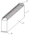
FIG. 9 is a perspective view of the precast portion of the composite girder;
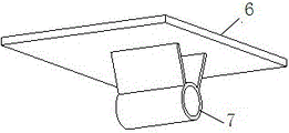
fig. 10 is a schematic view of a connection configuration of a flat plate and a horizontal threaded bushing.
The specific implementation mode is as follows:
in order to make the aforementioned and other features and advantages of the present invention comprehensible, embodiments accompanied with figures are described in detail below.
The utility model discloses assembled coincide roof beam slab installation auxiliary device includes two parallel arrangement's coincide roof beam prefabrication portion 1, establish respectively at the superimposed sheet elevation adjusting device 2 and the superimposed sheet 3 of support on superimposed sheet elevation adjusting device that two superimposed beam prefabrication portions are opposite.
One of them embodiment, above-mentioned superimposed sheet elevation adjusting device 2 includes L shape steel structure connecting piece 4 and the vertical adjusting screw 5 of vertical threaded connection on L shape steel structure connecting piece horizontal plate piece 11 that violently, the vertical slab piece constitute, 5 upper portions of vertical adjusting screw are fixed and are equipped with dull and stereotyped 6, dull and stereotyped 6 bottom surface fixedly connected with horizontal threaded sleeve 7 and threaded connection in horizontal threaded sleeve's horizontal screw 8, L shape steel structure connecting piece's vertical slab piece 9 passes through bolt 10 and is predetermine the pre-buried hole fixed connection on superimposed beam prefabrication portion opposite face, superimposed sheet 3 supports on the flat board.
Further, an angle iron template 12 is arranged between the upper surface of the flat plate and the lower surface of the laminated slab in a cushioning mode, the angle iron template comprises a transverse plate 13 and a longitudinal plate 14, the transverse plate 13 is arranged between the upper surface of the flat plate and the lower surface of the laminated slab, the inner side face of the longitudinal plate 14 is attached to the opposite face A of the prefabricated part of the laminated beam, and the inner end of the horizontal screw 8 is pressed against the outer side face of the longitudinal plate.
Further, the composite beam prefabricated part 1 comprises composite beam bottom steel bars 15, closed stirrups 16 arranged on the composite beam bottom steel bars at intervals and concrete 17 poured at the bottom of the composite beam prefabricated part, and the upper parts of the closed stirrups are exposed outside the concrete; before concrete pouring, the steel bars at the bottom of the superposed beam are bound and fixed with the lower parts of the closed stirrups, auxiliary steel bars 18 are hung above the closed stirrups 16, two ends of each auxiliary steel bar 18 are supported on the template B, the upper parts of the closed stirrups 16 are connected and pre-fixed with the auxiliary steel bars 18 through stirrup fixing buckles 19, and the stirrup fixing buckles 19 and the auxiliary steel bars 18 are detached after concrete pouring is finally set.
Furthermore, the stirrup fixing buckle 19 comprises two arc-shaped plates 20, a straight screw 21 penetrating through the upper parts of the two arc-shaped plates and provided with nuts at two ends, a hanging screw 22 penetrating through the lower parts of the two arc-shaped plates and two T-shaped screws 23 connected to the lower parts of the hanging screws, wherein the hanging screw 22 comprises a transverse screw 24, a longitudinal rod 25 connected to the middle section of the transverse screw and an inverted U-shaped connecting piece 26 connected to the lower part of the longitudinal rod and provided with two support legs, the two support legs of the inverted U-shaped connecting piece are penetrated by the T-shaped screws 23, the head ends 27 of the two T-shaped screws are arranged oppositely, the auxiliary steel bar 18 is clamped between the two arc-shaped plates 20, and the upper bar 28 of the closed stirrup is clamped between the head ends 27 of the two T-shaped screws.
The utility model discloses assembled coincide beam slab installation auxiliary device is because the coincide roof beam adopts and has adopted the closed stirrup, compares with traditional opening stirrup, has reduced a large amount of weldment work volume, has avoided the shortcoming of the latent fragility destruction that the stirrup welding brought moreover. The elevation adjusting device for the laminated slab has the adjusting functions in the horizontal direction and the vertical direction, can be used as a fulcrum of the angle template, and is flexible and convenient to install and dismantle.
The utility model relates to a construction method of an auxiliary device for mounting an assembled superposed beam slab,
firstly, manufacturing a plurality of stirrup fixing buckles;
secondly, manufacturing a template B according to the conventional method, binding the lower parts of the superposed beam bottom steel bars and the stirrups, wherein the steel bars on the upper parts of the stirrups are not bound temporarily, but fixing the stirrups by using stirrup fixing buckles, namely, firstly, penetrating the stirrup fixing buckles on an auxiliary steel bar 18 (the two ends of the auxiliary steel bar 18 are supported on the template B), then adjusting the positions of the stirrup fixing buckles according to the positions of the stirrups arranged at intervals, screwing nuts of a straight screw and a transverse screw on a hanging screw after the stirrups are adjusted in place, namely, fixing the stirrup fixing buckles, then fixing the auxiliary steel bars on the template, fixing the stirrups at the head ends of the stirrups by adjusting and screwing T-shaped screws on the stirrup fixing buckles, finally pouring concrete at the bottom of the superposed beam, removing the tendon fixing buckles after the concrete is finally solidified, and removing the template to form the prefabricated superposed beam with the closed stirrups after the concrete is maintained for a certain age;
the third step: processing the prefabricated laminated slab according to the conventional method;
the fourth step: transporting the laminated slab and the prefabricated part of the laminated beam with the closed stirrups to a construction site, after the construction of a vertical component (a wall or a column) is finished, penetrating the longitudinal steel bars 29 at the top of the laminated beam into the closed stirrups 16, temporarily fixing the longitudinal steel bars at the top of the beam to one side of the stirrups, temporarily fixing the longitudinal steel bars at the top of the beam in the middle of the stirrups when the cross section of the laminated beam is large enough, and binding the longitudinal steel bars at 4-5 positions by adopting iron wires for temporarily fixing the longitudinal steel bars at the top of the beam;
the fifth step: according to the conventional method, the superposed beam after the longitudinal steel bars on the beam top are temporarily fixed is hoisted and installed to form two superposed beam prefabricated parts which are arranged oppositely;
and a sixth step: after the laminated beam is installed and fixed, a pre-embedded hole pre-embedded in the opposite surface of the laminated beam is utilized, a laminated slab elevation adjusting device is fixed through a bolt, an angle steel template or an aluminum alloy angle template is placed on the laminated slab elevation adjusting device before the laminated slab is hoisted, the height is adjusted through a vertical screw rod on the laminated slab elevation adjusting device, the top surface of the angle steel template or the aluminum alloy angle template is just positioned at the standard height of the bottom of the laminated slab, the length of the steel or aluminum alloy angle template is the same as that of the laminated beam, and the angle steel template or the aluminum alloy angle template is tightly pressed in the horizontal direction by screwing a horizontal adjusting screw rod of the laminated slab elevation adjusting device;
the seventh step: and respectively hoisting the laminated slabs, placing the laminated slabs on the angle steel or aluminum alloy angle template, and then pouring the laminated concrete according to the conventional method.
Further, the interval or the number that superimposed sheet elevation adjusting device arranged in superimposed beam prefabricated part length direction is confirmed according to the width of every superimposed sheet, and every superimposed width is provided with 2 superimposed sheet elevation adjusting device at least.
The utility model discloses it has 3 to show the advantage:
(4) the reinforcing steel bars at the top of the superposed beam are pre-installed, so that the use of opening stirrups is reduced, and the construction speed is accelerated;
(5) the quick installation and positioning of the laminated slab in construction are realized;
(6) and the quick and flexible mold sealing of the lap joint of the laminated slab and the laminated beam is realized.
Any technical solution disclosed in the present invention is, unless otherwise stated, disclosed a numerical range if it is disclosed, and the disclosed numerical range is a preferred numerical range, and any person skilled in the art should understand that: the preferred value range is only the value with obvious or representative technical effect among a plurality of implementable values, and because the value is more, can't be exhaustively, so the utility model discloses just disclose some values in order to exemplify the technical scheme of the utility model discloses to, and, the above-mentioned numerical value of enumerating should not constitute the restriction to the utility model discloses create the protection scope.
If the terms "first," "second," etc. are used herein to define parts, those skilled in the art will recognize that: the terms "first" and "second" are used merely to distinguish one element from another in a descriptive sense and are not intended to have a special meaning unless otherwise stated.
Also, above-mentioned the utility model discloses if disclose or related to mutually fixed connection's spare part or structure, then, except that other the note, fixed connection can understand: a detachable fixed connection (for example using bolts or screws) is also understood as: non-detachable fixed connections (e.g. riveting, welding), but of course, fixed connections to each other may also be replaced by one-piece structures (e.g. manufactured integrally using a casting process) (unless it is obviously impossible to use an integral forming process).
In addition, the terms used in any aspect of the present disclosure as described above to indicate positional relationships or shapes include similar, analogous, or approximate states or shapes unless otherwise stated.
The utility model provides an arbitrary part both can be assembled by a plurality of solitary component parts and form, also can be the solitary part that the integrated into one piece technology was made.
Finally, it should be noted that the above embodiments are only used for illustrating the technical solutions of the present invention and not for limiting the same; although the present invention has been described in detail with reference to preferred embodiments, it should be understood by those skilled in the art that: the invention can be modified or equivalent substituted for some technical features; without departing from the spirit of the present invention, it should be understood that the scope of the claims is intended to cover all such modifications and variations.
Claims (5)
1. The utility model provides an assembled coincide beam slab installation auxiliary device which characterized in that: the composite slab comprises two composite beam prefabricated parts which are arranged in parallel, a composite slab elevation adjusting device which is respectively arranged on the opposite surfaces of the two composite beam prefabricated parts and a composite slab which is supported on the composite slab elevation adjusting device.
2. The fabricated composite beam panel installation assisting device according to claim 1, wherein: superimposed sheet elevation adjusting device includes the L shape steel structure connecting piece that violently, vertical slab constitute and vertical threaded connection vertical adjusting screw on the horizontal slab of L shape steel structure connecting piece, vertical adjusting screw is fixed on upper portion and is equipped with the flat board, dull and stereotyped bottom surface fixedly connected with horizontal thread sleeve pipe and threaded connection are in horizontal thread sheathed tube horizontal screw, the vertical slab of L shape steel structure connecting piece passes through the bolt and predetermines the pre-buried hole fixed connection on the opposite face of superimposed beam prefabrication portion, the superimposed sheet supports on the flat board.
3. The fabricated composite beam panel installation assisting device according to claim 2, wherein: the angle steel template is arranged between the upper surface of the flat plate and the lower surface of the composite slab in a cushioning mode, and comprises a transverse plate and a longitudinal plate, wherein the transverse plate is arranged between the upper surface of the flat plate and the lower surface of the composite slab, the inner side face of the longitudinal plate is attached to the opposite face of the prefabricated part of the composite beam, and the inner end of the horizontal screw is pressed on the outer side face of the longitudinal plate.
4. The fabricated composite beam panel installation assisting device according to claim 3, wherein: the superposed beam prefabricating part comprises superposed beam bottom reinforcing steel bars, closed stirrups arranged on the superposed beam bottom reinforcing steel bars at intervals and concrete poured at the bottom of the superposed beam prefabricating part, and the upper parts of the closed stirrups are exposed outside the concrete; before concrete is poured, the steel bars at the bottom of the superposed beam are bound and fixed with the lower part of the closed stirrup, the auxiliary steel bars are hung above the closed stirrup, the upper part of the closed stirrup is connected and pre-fixed with the auxiliary steel bars through the stirrup fixing buckles, and the stirrup fixing buckles and the auxiliary steel bars are removed after concrete pouring is finally set.
5. The fabricated composite beam panel installation assisting device according to claim 4, wherein: the stirrup fixing buckle comprises two arc-shaped plates, a straight screw rod penetrating through the upper parts of the two arc-shaped plates and provided with nuts at two ends, a hanging screw rod penetrating through the lower parts of the two arc-shaped plates and two T-shaped screw rods connected to the lower parts of the hanging screw rods, wherein the hanging screw rod comprises a transverse screw rod, a longitudinal rod connected to the middle section of the transverse screw rod and an inverted U-shaped connecting piece connected to the lower part of the longitudinal rod and provided with two support legs, the two support legs of the inverted U-shaped connecting piece are penetrated by the T-shaped screw rods, the head ends of the two T-shaped screw rods are arranged relatively, the auxiliary steel bar clamp is arranged between the two arc-shaped plates, and the upper steel bar strip clamp of the.
Priority Applications (1)
| Application Number | Priority Date | Filing Date | Title |
|---|---|---|---|
| CN201920186288.4U CN210049614U (en) | 2019-02-02 | 2019-02-02 | Auxiliary device for mounting assembly type superposed beam plate |
Applications Claiming Priority (1)
| Application Number | Priority Date | Filing Date | Title |
|---|---|---|---|
| CN201920186288.4U CN210049614U (en) | 2019-02-02 | 2019-02-02 | Auxiliary device for mounting assembly type superposed beam plate |
Publications (1)
| Publication Number | Publication Date |
|---|---|
| CN210049614U true CN210049614U (en) | 2020-02-11 |
Family
ID=69376938
Family Applications (1)
| Application Number | Title | Priority Date | Filing Date |
|---|---|---|---|
| CN201920186288.4U Expired - Fee Related CN210049614U (en) | 2019-02-02 | 2019-02-02 | Auxiliary device for mounting assembly type superposed beam plate |
Country Status (1)
| Country | Link |
|---|---|
| CN (1) | CN210049614U (en) |
Cited By (4)
| Publication number | Priority date | Publication date | Assignee | Title |
|---|---|---|---|---|
| CN109707173A (en) * | 2019-02-02 | 2019-05-03 | 福建工程学院 | Assembled overlaps beam slab installation auxiliary device and its construction method |
| CN111188488A (en) * | 2020-03-05 | 2020-05-22 | 朱明亮 | Concatenation formula building templates suitable for polymorphic type |
| CN113027026A (en) * | 2021-04-02 | 2021-06-25 | 青岛腾远设计事务所有限公司 | Inverted U-shaped prestress laminated floor slab and installation method thereof |
| CN114075878A (en) * | 2021-11-16 | 2022-02-22 | 中交一公局集团有限公司 | Assembled superimposed sheet installation device |
-
2019
- 2019-02-02 CN CN201920186288.4U patent/CN210049614U/en not_active Expired - Fee Related
Cited By (5)
| Publication number | Priority date | Publication date | Assignee | Title |
|---|---|---|---|---|
| CN109707173A (en) * | 2019-02-02 | 2019-05-03 | 福建工程学院 | Assembled overlaps beam slab installation auxiliary device and its construction method |
| CN111188488A (en) * | 2020-03-05 | 2020-05-22 | 朱明亮 | Concatenation formula building templates suitable for polymorphic type |
| CN113027026A (en) * | 2021-04-02 | 2021-06-25 | 青岛腾远设计事务所有限公司 | Inverted U-shaped prestress laminated floor slab and installation method thereof |
| CN114075878A (en) * | 2021-11-16 | 2022-02-22 | 中交一公局集团有限公司 | Assembled superimposed sheet installation device |
| CN114075878B (en) * | 2021-11-16 | 2022-07-22 | 中交一公局集团有限公司 | Assembled superimposed sheet installation device |
Similar Documents
| Publication | Publication Date | Title |
|---|---|---|
| CN210049614U (en) | Auxiliary device for mounting assembly type superposed beam plate | |
| CN109707173B (en) | Construction method of assembly type laminated beam plate installation auxiliary device | |
| WO2008133460A1 (en) | Composite concrete column and construction method using the same | |
| KR101084736B1 (en) | A shear connector which install the position-fixing device, a girder with that connector, and the method of slab construction using it all | |
| KR100447013B1 (en) | Beam system composed of asymmetric steel section with web hole and concrete | |
| KR101049880B1 (en) | Composite beam having concrete member precasted or casted in place and, construction methods using the same | |
| KR101548114B1 (en) | Steel concrete composite beam having increased composite effect of connecting part at the cross-section change part | |
| CN109537811A (en) | The assembly method of steel structure node, prefabricated post and preparation method thereof, column beam | |
| KR100854224B1 (en) | Precast half depth cantilever deck and constructing method of such bridge deck | |
| CN110056085A (en) | Can quick assembling FRP profile bean column node | |
| JPH03250130A (en) | Constructing method using reinforced steel framed reinforced half-precast concrete beam without main reinforcing steel | |
| CN106894544B (en) | Embedded single-layer steel plate-concrete combined shear wall and construction method thereof | |
| CN216239039U (en) | Beam column connecting node | |
| CN115324341A (en) | Construction method of steel-concrete composite beam | |
| KR100695491B1 (en) | A fixing device, a pre-fabricating forms for concrete-structure and the construction method thereof | |
| JP3103808B2 (en) | Net formwork method for walls and floors | |
| KR0180077B1 (en) | Dech girder of reinforced concrete slab | |
| CN218843330U (en) | Clamping connection structure for concrete beam connection | |
| JP2620118B2 (en) | Net formwork method for walls and floors | |
| CN213359049U (en) | Assembled superimposed sheet | |
| CN219794190U (en) | Main and secondary beam connecting node capable of controlling thickness of cast-in-situ floor slab | |
| CN215406735U (en) | Shear force wall reinforcing structure | |
| CN213267482U (en) | Bridge with anti-seismic structure | |
| CN212224624U (en) | Formwork device and outer wall assembly structure that prefabricated outer wall connects | |
| JPH01290853A (en) | Composite floor board using deck plate |
Legal Events
| Date | Code | Title | Description |
|---|---|---|---|
| GR01 | Patent grant | ||
| GR01 | Patent grant | ||
| CF01 | Termination of patent right due to non-payment of annual fee | ||
| CF01 | Termination of patent right due to non-payment of annual fee |
Granted publication date: 20200211 |