CN210036125U - Diamino amide drying apparatus - Google Patents
Diamino amide drying apparatus Download PDFInfo
- Publication number
- CN210036125U CN210036125U CN201920471177.8U CN201920471177U CN210036125U CN 210036125 U CN210036125 U CN 210036125U CN 201920471177 U CN201920471177 U CN 201920471177U CN 210036125 U CN210036125 U CN 210036125U
- Authority
- CN
- China
- Prior art keywords
- box
- connecting plate
- upper cover
- box body
- support frame
- Prior art date
- Legal status (The legal status is an assumption and is not a legal conclusion. Google has not performed a legal analysis and makes no representation as to the accuracy of the status listed.)
- Expired - Fee Related
Links
- PYHOFAHZHOBVGV-UHFFFAOYSA-N triazane Chemical compound NNN PYHOFAHZHOBVGV-UHFFFAOYSA-N 0.000 title claims description 13
- 238000001035 drying Methods 0.000 title abstract description 17
- 238000007599 discharging Methods 0.000 claims abstract description 32
- 150000001408 amides Chemical class 0.000 claims abstract description 8
- 239000000463 material Substances 0.000 claims description 29
- 238000007789 sealing Methods 0.000 claims description 16
- 238000010438 heat treatment Methods 0.000 claims description 9
- 238000003860 storage Methods 0.000 claims description 6
- 238000010079 rubber tapping Methods 0.000 description 6
- 230000000694 effects Effects 0.000 description 3
- 238000003756 stirring Methods 0.000 description 2
- 206010066054 Dysmorphism Diseases 0.000 description 1
- 230000009286 beneficial effect Effects 0.000 description 1
- 230000000903 blocking effect Effects 0.000 description 1
- 238000007664 blowing Methods 0.000 description 1
- 239000002178 crystalline material Substances 0.000 description 1
- 239000003814 drug Substances 0.000 description 1
- 238000004519 manufacturing process Methods 0.000 description 1
- 238000012986 modification Methods 0.000 description 1
- 230000004048 modification Effects 0.000 description 1
- 238000003466 welding Methods 0.000 description 1
Images


Landscapes
- Drying Of Solid Materials (AREA)
Abstract
The utility model discloses a diamino acid amide drying apparatus, including box and hot plate, the upper end of box is closely laminated and is provided with the upper cover, and the inside of box and upper cover has all seted up the inner chamber, the inside of box and upper cover all is provided with the inner box, the lower extreme fixedly connected with montant of motor, the internal surface that sets up at the box is inlayed to the hot plate, the upper end right side fixed mounting of upper cover has the feeder hopper, fixed mounting has the discharging pipe under the box, the inside through connection of discharging pipe has the connecting rod, and the upper end welded connection of connecting rod has the guide block to the lower extreme welded connection who connects has sealed piece, the bottom fixedly connected with support frame of sealed piece, and the upper end of support frame is located the inside of spout, the bottom right side fixedly connected with intake pipe of box. This diamino acid amide drying apparatus, it is comparatively abundant to dry, and the ejection of compact after convenient stoving to can not block up the discharge gate when the ejection of compact.
Description
Technical Field
The utility model relates to a relevant technical field of diamino acid amide specifically is a diamino acid amide drying apparatus.
Background
Diaminoamides, which are derivatives of amides and are used mainly in industry and medicine, require drying of the product obtained during the diaminoamide production process in order to obtain a dry crystalline material, and therefore require a corresponding dryer to assist in the completion of the operation.
However, the existing diaminodiamide dryers in the market are often insufficient in drying, so that the heated area of materials is limited, the general diaminodiamide dryers are inconvenient for discharging materials after drying, and the discharge hole is easily blocked by the common diaminodiamide dryers during discharging, so that a diaminodiamide dryer is provided, and the problems provided in the prior art are solved.
SUMMERY OF THE UTILITY MODEL
An object of the utility model is to provide a diamino acid amide drying apparatus to solve most diamino acid amide drying apparatus stoving of proposition in the above-mentioned background art and abundant inadequately, and the ejection of compact after inconvenient stoving, and block up the problem of discharge gate easily when the ejection of compact.
In order to achieve the above object, the utility model provides a following technical scheme: a diaminodiamide drying apparatus comprises a box body and a heating plate, wherein an upper cover is closely attached to the upper end of the box body, inner cavities are formed in the box body and the upper cover, an inner box is arranged in the box body and the upper cover, a motor is fixedly mounted at the top end of the upper cover, a vertical rod is fixedly connected to the lower end of the motor, a first connecting plate is welded to the outer surface of the vertical rod, a second connecting plate is welded to the adjacent position of the first connecting plate, the heating plate is embedded in the inner surface of the box body and is electrically connected with a storage battery, a feeding hopper is fixedly mounted on the right side of the upper end of the upper cover, a discharging pipe is fixedly mounted under the box body, a sliding groove is formed in the outer surface of the discharging pipe at an equal angle, a connecting rod penetrates through the inner part of the discharging pipe, a guide block is welded to the upper, the bottom fixedly connected with support frame of sealed piece, and the upper end of support frame is located the inside of spout, the bottom right side fixedly connected with intake pipe of box.
Preferably, the inner surface of the inner box is of a honeycomb structure, and the shape of the longitudinal section of the inner box is consistent with that of the longitudinal section of the box body.
Preferably, the first connecting plate and the second connecting plate are both in a spiral structure, the screwing directions of the first connecting plate and the second connecting plate are opposite, and the width of the upper end of the second connecting plate is larger than that of the lower end of the second connecting plate.
Preferably, the material guiding block is of a conical structure and is fixedly connected with the sealing block through a connecting rod.
Preferably, the outer diameter of the sealing block is equal to the inner diameter of the tapping pipe, and the sealing block is connected with the tapping pipe in a threaded manner.
Preferably, the support frames are distributed in an annular array relative to the center of the sealing block, the longitudinal section of each support frame is U-shaped, and the support frames are of a sliding structure on the discharge pipe.
Compared with the prior art, the beneficial effects of the utility model are that: the diamino amide dryer is sufficient in drying, convenient for discharging after drying, and free from blocking a discharging hole during discharging;
1. the vertical rods, the first connecting plate and the second connecting plate are arranged inside the box body, so that the first connecting plate and the second connecting plate are driven to rotate by the rotation of the vertical rods, materials inside the box body can be stirred conveniently, the interior of the materials are heated uniformly, the drying effect is better, the inner box is arranged to be of a honeycomb structure, hot air flowing in the inner cavity can uniformly blow towards the materials through the holes in the inner box, the surface of the materials can be heated sufficiently, and the materials are dried uniformly;
2. the discharge pipe is arranged at the bottom end of the box body, and the box body is integrally of a conical structure, so that materials can be conveniently concentrated in the discharge pipe, the materials can be discharged more easily and more thoroughly, and the material residue is reduced;
3. through being provided with connecting rod, guide block, sealed piece and support frame in the inside of discharging pipe for this structure can dredge the export of discharging pipe under the condition that does not influence the ejection of compact, prevents the jam of discharge gate.
Drawings
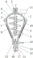
Fig. 1 is a schematic view of the front cross-sectional structure of the present invention;
FIG. 2 is an enlarged schematic view of the structure at A of FIG. 1 according to the present invention;
FIG. 3 is a schematic view of the sectional structure of the discharge tube and the support frame in a top view;
fig. 4 is a schematic view of the overlooking section structure of the discharge tube and the support frame of the present invention.
In the figure: 1. a box body; 2. an upper cover; 3. an inner cavity; 4. an inner box; 5. a motor; 6. a vertical rod; 7. a first connecting plate; 8. a second connecting plate; 9. heating plates; 10. a storage battery; 11. a feed hopper; 12. a discharge pipe; 13. a chute; 14. a connecting rod; 15. a material guide block; 16. a sealing block; 17. a support frame; 18. an air inlet pipe.
Detailed Description
The technical solution in the embodiments of the present invention will be clearly and completely described below with reference to the drawings in the embodiments of the present invention, and it is obvious that the described embodiments are only some embodiments of the present invention, rather than all embodiments, and all other embodiments obtained by a person of ordinary skill in the art without creative work belong to the protection scope of the present invention based on the embodiments of the present invention.
Referring to fig. 1-4, the present invention provides a technical solution: a diaminodiamide drying apparatus comprises a box body 1, an upper cover 2, an inner cavity 3, an inner box 4, a motor 5, a vertical rod 6, a first connecting plate 7, a second connecting plate 8, a heating plate 9, a storage battery 10, a feeding hopper 11, a discharging pipe 12, a chute 13, a connecting rod 14, a material guide block 15, a sealing block 16, a supporting frame 17 and an air inlet pipe 18, wherein the upper end of the box body 1 is tightly attached with the upper cover 2, the inner cavity 3 is respectively arranged inside the box body 1 and the upper cover 2, the inner box 4 is respectively arranged inside the box body 1 and the upper cover 2, the motor 5 is fixedly arranged at the top end of the upper cover 2, the lower end of the motor 5 is fixedly connected with the vertical rod 6, the outer surface of the vertical rod 6 is welded and connected with the first connecting plate 7, the second connecting plate 8 is welded and connected at the adjacent position of the first connecting plate 7, the heating plate 9, upper end right side fixed mounting of upper cover 2 has feeder hopper 11, fixed mounting has discharging pipe 12 under box 1, and the outer surface of discharging pipe 12 is equiangular and has seted up spout 13, the inside through connection of discharging pipe 12 has connecting rod 14, and the upper end welded connection of connecting rod 14 has guide block 15, and the lower extreme welded connection of connecting rod 14 has sealed piece 16, the bottom fixedly connected with support frame 17 of sealed piece 16, and the upper end of support frame 17 is located the inside of spout 13, the bottom right side fixedly connected with intake pipe 18 of box 1.
As shown in fig. 1, the inner surface of the inner box 4 is of a honeycomb structure, the longitudinal section of the inner box 4 is consistent with that of the box body 1, hot air in the inner cavity 3 can be uniformly blown to materials through the holes in the inner box 4, so that the materials can be sufficiently heated, the first connecting plate 7 and the second connecting plate 8 are of a spiral structure, the screwing directions of the first connecting plate 7 and the second connecting plate 8 are opposite, the width of the upper end of the second connecting plate 8 is larger than that of the lower end of the second connecting plate 8, and the materials can be stirred more uniformly through the combined action of the first connecting plate 7 and the second connecting plate 8;
as shown in fig. 1, the material guiding block 15 is a conical structure, and the material guiding block 15 is fixedly connected with the sealing block 16 through the connecting rod 14, so that the interior of the discharging pipe 12 can be conveniently dredged through the material guiding block 15, the outer diameter size of the sealing block 16 is equal to the inner diameter size of the discharging pipe 12, and the connection mode of the sealing block 16 and the discharging pipe 12 is a threaded connection, so that the opening and closing of the discharging pipe 12 can be conveniently controlled through the sealing block 16 and the sealing block 16 of the discharging pipe 12 and the discharging pipe 12;
as shown in fig. 3 and 4, the supporting frames 17 are distributed in an annular array with respect to the center of the sealing block 16, the longitudinal cross-sectional shape of the supporting frames 17 is "U" shaped, and the supporting frames 17 have a sliding structure on the tapping pipe 12, so that the supporting frames 17 support the tapping pipe 12 and do not affect the tapping of the tapping pipe 12.
The working principle is as follows: when the diaminoamide dryer is used, firstly, diaminoamide materials are thrown into the interior of the box body 1 through the feed hopper 11, then the motor 5 with the model of Y90S-2 is opened, the motor 5 drives the vertical rod 6 to rotate, meanwhile, a switch on the storage battery 10 is opened, the storage battery 10 supplies power to the heating plate 9, the heating plate 9 is heated, then the corresponding air blowing device is connected with the air inlet pipe 18, the air inlet pipe 18 can blow air into the inner cavity 3, at the moment, the vertical rod 6 drives the first connecting plate 7 and the second connecting plate 8 to rotate, the first connecting plate 7 and the second connecting plate 8 stir the materials, the materials are dried and stirred, the drying efficiency of the materials is improved, wherein the spiral directions of the first connecting plate 7 and the second connecting plate 8 are opposite, and the material moving directions on the first connecting plate 7 and the second connecting plate 8 are also opposite, consequently can make the material more even by the stirring, under the effect of hot plate 9, make the air in the inner chamber 3 be heated, and hot-air gets into the material through the hole on inner box 4, make the material be heated more evenly, the stoving effect is better, after the stoving is finished, pull down sealed piece 16 anticlockwise rotation from discharging pipe 12, at this moment, sealed piece 16 passes through support frame 17 and slides on discharging pipe 12, and support sealed piece 16, and do not influence the ejection of compact of discharging pipe 12, inside at discharging pipe 12 is provided with connecting rod 14 and guide block 15, when discharging pipe 12 port blocks up, the accessible promotes sealed piece 16 from top to bottom, make guide block 15 dredge the inside of discharging pipe 12, prevent the jam of discharging pipe 12, this is the theory of operation of this diamino amide drying apparatus.
The utility model discloses the standard part that uses all can purchase from the market, and dysmorphism piece all can be customized according to the description with the record of drawing of description, and the concrete connected mode of each part all adopts conventional means such as ripe bolt, rivet, welding among the prior art, and machinery, part and equipment all adopt among the prior art, and conventional model, including the conventional connected mode among the circuit connection adoption prior art, and the details are not repeated here, and the content that does not make detailed description in this description belongs to the prior art that skilled person in the art knows.
Although the present invention has been described in detail with reference to the foregoing embodiments, it will be apparent to those skilled in the art that modifications may be made to the embodiments or portions thereof without departing from the spirit and scope of the invention.
Claims (6)
1. The utility model provides a diamino acid amide drying-device, includes box (1) and hot plate (9), its characterized in that: the upper end of the box body (1) is tightly attached with an upper cover (2), inner cavities (3) are formed in the box body (1) and the upper cover (2), inner boxes (4) are arranged in the box body (1) and the upper cover (2), a motor (5) is fixedly mounted at the top end of the upper cover (2), a vertical rod (6) is fixedly connected at the lower end of the motor (5), a first connecting plate (7) is welded on the outer surface of the vertical rod (6), a second connecting plate (8) is welded at the adjacent position of the first connecting plate (7), the heating plate (9) is embedded on the inner surface of the box body (1), the heating plate (9) is electrically connected with a storage battery (10), a feeding hopper (11) is fixedly mounted at the right side of the upper end of the upper cover (2), and a discharging pipe (12) is fixedly mounted under the box body (1), and the surface of discharging pipe (12) is equiangular seted up spout (13), the inside through connection of discharging pipe (12) has connecting rod (14), and the upper end welded connection of connecting rod (14) has guide block (15) to the lower extreme welded connection of connecting rod (14) has sealed piece (16), the bottom fixedly connected with support frame (17) of sealed piece (16), and the upper end of support frame (17) is located the inside of spout (13), the bottom right side fixedly connected with intake pipe (18) of box (1).
2. A diamino amide dryer according to claim 1, characterized in that: the inner surface of the inner box (4) is of a honeycomb structure, and the shape of the longitudinal section of the inner box (4) is consistent with that of the longitudinal section of the box body (1).
3. A diamino amide dryer according to claim 1, characterized in that: first connecting plate (7) and second connecting plate (8) all are helical structure, and first connecting plate (7) and the precession opposite direction of second connecting plate (8) to the upper end width dimension of second connecting plate (8) is greater than lower extreme width dimension.
4. A diamino amide dryer according to claim 1, characterized in that: the material guide block (15) is of a conical structure, and the material guide block (15) is fixedly connected with the sealing block (16) through a connecting rod (14).
5. A diamino amide dryer according to claim 1, characterized in that: the outer diameter of the sealing block (16) is equal to the inner diameter of the discharge pipe (12), and the sealing block (16) is connected with the discharge pipe (12) in a threaded manner.
6. A diamino amide dryer according to claim 1, characterized in that: the support frame (17) is distributed in an annular array relative to the center of the sealing block (16), the longitudinal section of the support frame (17) is U-shaped, and the support frame (17) is of a sliding structure on the discharge pipe (12).
Priority Applications (1)
| Application Number | Priority Date | Filing Date | Title |
|---|---|---|---|
| CN201920471177.8U CN210036125U (en) | 2019-04-09 | 2019-04-09 | Diamino amide drying apparatus |
Applications Claiming Priority (1)
| Application Number | Priority Date | Filing Date | Title |
|---|---|---|---|
| CN201920471177.8U CN210036125U (en) | 2019-04-09 | 2019-04-09 | Diamino amide drying apparatus |
Publications (1)
| Publication Number | Publication Date |
|---|---|
| CN210036125U true CN210036125U (en) | 2020-02-07 |
Family
ID=69358501
Family Applications (1)
| Application Number | Title | Priority Date | Filing Date |
|---|---|---|---|
| CN201920471177.8U Expired - Fee Related CN210036125U (en) | 2019-04-09 | 2019-04-09 | Diamino amide drying apparatus |
Country Status (1)
| Country | Link |
|---|---|
| CN (1) | CN210036125U (en) |
Cited By (2)
| Publication number | Priority date | Publication date | Assignee | Title |
|---|---|---|---|---|
| CN111664699A (en) * | 2020-06-16 | 2020-09-15 | 谢轶 | Drying device is used in vegetable oil production |
| CN112239028A (en) * | 2020-11-10 | 2021-01-19 | 叶延森 | Building engineering is with preventing blockking up mechanical hopper |
-
2019
- 2019-04-09 CN CN201920471177.8U patent/CN210036125U/en not_active Expired - Fee Related
Cited By (3)
| Publication number | Priority date | Publication date | Assignee | Title |
|---|---|---|---|---|
| CN111664699A (en) * | 2020-06-16 | 2020-09-15 | 谢轶 | Drying device is used in vegetable oil production |
| CN112239028A (en) * | 2020-11-10 | 2021-01-19 | 叶延森 | Building engineering is with preventing blockking up mechanical hopper |
| CN112239028B (en) * | 2020-11-10 | 2022-02-25 | 江苏省水利科学研究院 | Building engineering is with preventing blockking up mechanical hopper |
Similar Documents
| Publication | Publication Date | Title |
|---|---|---|
| CN210036125U (en) | Diamino amide drying apparatus | |
| CN212930901U (en) | Drying device is used in grain oil processing | |
| CN109405515A (en) | A kind of granulated material drier | |
| CN213811606U (en) | Plastic particle drying machine | |
| CN212962548U (en) | Multifunctional putty powder production equipment | |
| CN214950336U (en) | High-efficient drying equipment of zinc powder | |
| CN212492612U (en) | Look female production is with high-efficient machine that mixes that has heating function | |
| CN205951085U (en) | Injection molding machine feeding equipment | |
| CN108185154A (en) | A kind of feed granulating equipment | |
| CN211177850U (en) | Sesame drying device is used in sesame sauce production | |
| CN210058015U (en) | Office paper shredder shell raw material for production mixing device | |
| CN214892467U (en) | High-efficient drying device is used in processing of function rice | |
| CN214620419U (en) | Rice drying device with self-cleaning function | |
| CN209310424U (en) | A kind of Feed Manufacturing flash baking equipment | |
| CN213307343U (en) | High-temperature sterilization drying energy-saving equipment for improved high-efficiency fresh fruits | |
| CN205902421U (en) | Domestic integration corn thresher | |
| CN215809880U (en) | Granule drying device is used in plastic products processing | |
| CN110492056A (en) | Button cell positive plate process units and its working method | |
| CN210525819U (en) | Master batch blown film device | |
| CN218365413U (en) | Vacuum ceramic extruder | |
| CN210952173U (en) | Drying device | |
| CN214682742U (en) | Sesame oil squeezes processing and uses raw materials edulcoration device | |
| CN217275410U (en) | Drying device for plastic product processing | |
| CN213966991U (en) | Reducing mechanism is used in feed production processing | |
| CN219956003U (en) | Mineral powder ultrafine powder dryer |
Legal Events
| Date | Code | Title | Description |
|---|---|---|---|
| GR01 | Patent grant | ||
| CF01 | Termination of patent right due to non-payment of annual fee |
Granted publication date: 20200207 |
|
| CF01 | Termination of patent right due to non-payment of annual fee |