CN210023405U - Linkage mechanism on punch press - Google Patents
Linkage mechanism on punch press Download PDFInfo
- Publication number
- CN210023405U CN210023405U CN201920567731.2U CN201920567731U CN210023405U CN 210023405 U CN210023405 U CN 210023405U CN 201920567731 U CN201920567731 U CN 201920567731U CN 210023405 U CN210023405 U CN 210023405U
- Authority
- CN
- China
- Prior art keywords
- steering gear
- gear
- gears
- assembly
- rotating shaft
- Prior art date
- Legal status (The legal status is an assumption and is not a legal conclusion. Google has not performed a legal analysis and makes no representation as to the accuracy of the status listed.)
- Active
Links
Images


Abstract
The utility model discloses a link gear on punch press, including frame, main motor, punching press runner, punching press assembly and pay-off assembly, main motor sets up frame upper portion, the pay-off assembly sets up the frame lower part, the punching press runner drive the punching press assembly motion, main motor one side is equipped with the flywheel, the flywheel drive the punching press runner rotates, set up first pivot on the punching press runner, still be provided with second pivot, third pivot, first steering gear, second steering gear and third steering gear in the frame, will through multistage linkage the power of main motor is conveyed on the pay-off assembly, make punching press assembly and pay-off assembly form the power linkage, saved the production energy consumption greatly, make whole assembly space compacter.
Description
Technical Field
The utility model belongs to the technical field of the punch press manufacturing technology and specifically relates to a link gear on punch press is related to.
Background
The punch press drives a flywheel through a motor, and drives a crank connecting rod mechanism to enable a sliding block to move up and down through a clutch so as to drive a drawing die to form a steel plate. The double-acting means that the press is provided with two slide blocks which are an inner slide block and an outer slide block, the inner slide block drives a male die or a female die of the die, the outer slide block drives a blank holder on the die, the blank holder firstly acts to press the edge of a steel plate during drawing, and the inner slide block then acts to draw. The steel plate feeding mechanism at the lower part of the traditional punch press is generally driven by an independent driving motor, so that the production energy consumption is increased, and the equipment assembly space is enlarged.
Disclosure of Invention
The utility model provides a not enough to prior art, the utility model provides a link gear on punch press, simple structure will through multistage linkage the power of main motor conveys on the pay-off assembly, make punching press assembly and pay-off assembly form the power linkage, saved the production energy consumption greatly, make whole assembly space compacter.
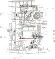
The utility model provides a technical scheme that its technical problem adopted is: a linkage mechanism on a punch press comprises a rack, a main motor, a stamping rotating wheel, a stamping assembly and a feeding assembly, wherein the main motor is arranged at the upper part of the rack, the feeding assembly is arranged at the lower part of the rack, the stamping rotating wheel drives the stamping assembly to move, a flywheel is arranged at one side of the main motor and drives the stamping rotating wheel to rotate, a first rotating shaft is arranged on the stamping rotating wheel, a second rotating shaft, a third rotating shaft, a first steering gear, a second steering gear and a third steering gear are further arranged on the rack, the first rotating shaft is connected with a rotating shaft at one end of the first steering gear through a group of bevel gears, the first steering gear is connected with the second steering gear and converts force from transverse rotation into longitudinal rotation, and the second steering gear is connected with the third steering gear through the second rotating shaft and the third rotating shaft which are longitudinally arranged, and torque protectors are arranged at the connecting joints, the third steering gear converts force from longitudinal rotation into transverse rotation, and the third steering gear drives the feeding assembly to move.
In the above technical solution, preferably, the feeding assembly includes a support, a steel plate conveying mechanism, a support plate is installed on the support, a movable plate is arranged on the supporting plate, the steel plate conveying mechanism is arranged on the movable plate, one end of the movable plate is rotatably connected on the supporting plate, the other end of the movable plate is provided with a round rod which downwards penetrates through the supporting plate, the round rod penetrates through a through hole on the supporting plate, the diameter of the through hole is larger than that of the round rod, a cylindrical cam is arranged below the through hole, the groove on the cylindrical cam is two parallel but non-coincident paths, the bottom end of the round rod is arranged in the groove, the cylindrical cam rotates to drive the round rod to do reciprocating swing in the through hole, so that the movable plate is driven to drive the steel plate conveying mechanism to do reciprocating swing.
In the above technical scheme, preferably, the steel plate conveying mechanism includes a conveying roller, a pressing wheel, a conveying table and a base, the base is mounted on the movable plate, the conveying table is mounted on two sides of the base, the conveying roller is mounted inside the base, the pressing wheel is mounted above the conveying roller, and the steel plate is placed between the conveying roller and the pressing wheel.
In the above technical scheme, preferably, the feeding assembly further includes a transmission base, the transmission base is connected with a transmission shaft in a rotating mode, the transmission shaft is connected with the third steering gear, a first gear and a second gear are arranged on two sides of the transmission shaft, the conveying roller is driven to rotate by a third gear on one side of the base, the pinch roller is driven to rotate by a fourth gear on one side of the base, the third gear is meshed with the fourth gear, the cylindrical cam is driven to rotate by a fifth gear on the left side of the support, a link mechanism is further arranged on the support, the first gear is connected with the third gear through the link mechanism, the first gear synchronously drives the third gear and the fourth gear to rotate, and the fifth gear is connected with the second gear through a chain.
The utility model has the advantages that: the structure is simple, the power of the main motor is transmitted to the feeding assembly through multi-stage linkage, so that the punching assembly and the feeding assembly form power linkage, the production energy consumption is greatly saved, and the whole assembly space is more compact.
Drawings
The present invention will be further explained with reference to the drawings and examples.
Fig. 1 is a schematic front view of the present invention.
Fig. 2 is a schematic structural diagram of another view angle of the present invention.
Fig. 3 is a schematic structural diagram of another view angle of the present invention.
Fig. 4 is a schematic structural diagram of another viewing angle of the present invention.
Fig. 5 is a schematic structural view of the feeding assembly of the present invention.
Fig. 6 is a sectional view taken along line a-a in fig. 5.
In the drawing, 1, a frame, 2, a main motor, 3, a stamping rotating wheel, 4, a feeding assembly, 5, a flywheel, 6, a first rotating shaft, 7, a second rotating shaft, 8, a third rotating shaft, 9, a first steering gear, 10, a second steering gear, 11, a third steering gear, 12, a torque protector, 13, a support, 15, a support plate, 16, a movable plate, 17, a round rod, 18, a through hole, 19, a cylindrical cam, 21, a conveying roller, 22, a pressing wheel, 23, a conveying table, 24, a base, 25, a transmission seat, 27, a first gear, 28, a second gear, 29, a third gear, 30, a fourth gear, 31, a fifth gear, 32, a connecting rod mechanism, 33, a chain and 35 are arranged.
Detailed Description
In fig. 1-6, a linkage mechanism on a punch press comprises a frame 1, a main motor 2, a punching rotating wheel 3, a punching assembly and a feeding assembly 4, wherein the main motor 2 is arranged at the upper part of the frame 1, the feeding assembly 4 is arranged at the lower part of the frame 1, the punching rotating wheel 3 drives the punching assembly to move, a flywheel 5 is arranged at one side of the main motor 2, the flywheel 5 drives the punching rotating wheel 3 to rotate, a first rotating shaft 6 is arranged on the punching rotating wheel 3, a second rotating shaft 7, a third rotating shaft 8, a first steering gear 9, a second steering gear 10 and a third steering gear 11 are further arranged on the frame 1, the first rotating shaft 6 is connected with a rotating shaft at one end of the first steering gear 9 through a group of bevel gears, the first steering gear 9 is connected with the second steering gear 10 to convert a force from a transverse rotation to a longitudinal rotation, the second steering gear 10 and the third steering gear 11 are connected through the second rotating shaft 7 and the third rotating shaft 8 which are longitudinally arranged, the torque protectors 12 are arranged at the connecting joints, the third steering gear 11 converts force from longitudinal rotation into transverse rotation, and the third steering gear 11 drives the feeding assembly 4 to move.
Wherein the feeding assembly 4 comprises a bracket and a steel plate conveying mechanism, a support plate 15 is arranged on the bracket 13, a movable plate 16 is provided on the support plate 15, the steel plate conveying mechanism 14 is mounted on the movable plate 16, one end of the movable plate 16 is rotatably connected to the support plate 15, the other end of the movable plate 16 is provided with a round bar 17 passing through the support plate 15 downwards, the round rod 17 passes through a through hole 18 on the supporting plate 15, the diameter of the through hole 18 is larger than that of the round rod 17, a cylindrical cam 19 is arranged below the through hole 18, a groove on the cylindrical cam 19 is a two-section parallel but non-coincident path, the bottom end of the round rod 17 is arranged in the groove, the cylindrical cam 19 rotates to drive the round rod 17 to reciprocate in the through hole 18, so as to drive the movable plate 16 to drive the steel plate conveying mechanism to reciprocate.
The steel plate conveying mechanism comprises a conveying roller 21, a pressing wheel 22, a conveying table 23 and a base 24, the base 24 is installed on the movable plate 16, the conveying table 23 is installed on two sides of the base 24, the conveying roller 21 is installed inside the base 24, the pressing wheel 22 is installed above the conveying roller 21, and a steel plate 35 is placed between the conveying roller 21 and the pressing wheel 22.
The feeding assembly 4 further comprises a transmission seat 25, the transmission seat 25 is rotatably connected with a transmission shaft, the transmission shaft is connected with the third steering gear 11, a first gear 27 and a second gear 28 are arranged on two sides of the transmission shaft, the conveying roller 21 is rotated by a third gear 29 on one side of the base 24, the pinch roller 22 is driven to rotate by a fourth gear 30 on one side of the base 24, the third gear 29 is meshed with the fourth gear 30, the cylindrical cam 19 is rotated by a fifth gear 31 on the left side of the bracket 13, the bracket 13 is further provided with a link mechanism 32, the first gear 27 and the third gear 29 are connected through the link mechanism 32, the first gear 27 synchronously drives the third gear 29 and the fourth gear 30 to rotate, and the fifth gear 31 is connected with the second gear 28 through a chain 33.
Claims (4)
1. The utility model provides a link gear on punch press, includes frame, main motor, punching press runner, punching press assembly and pay-off assembly, main motor sets up frame upper portion, the pay-off assembly sets up the frame lower part, the driving of punching press runner the motion of punching press assembly, its characterized in that: the feeding assembly is characterized in that a flywheel is arranged on one side of the main motor and drives the stamping rotating wheel to rotate, a first rotating shaft is arranged on the stamping rotating wheel, a second rotating shaft, a third rotating shaft, a first steering gear, a second steering gear and a third steering gear are further arranged on the rack, the first rotating shaft is connected with a rotating shaft at one end of the first steering gear through a group of bevel gears, the first steering gear is connected with the second steering gear and converts force from transverse rotation into longitudinal rotation, the second steering gear is connected with the third steering gear through the second rotating shaft and the third rotating shaft which are longitudinally arranged, a torque protector is arranged at a connecting joint, the third steering gear converts force from longitudinal rotation into transverse rotation, and the third steering gear drives the feeding assembly to move.
2. The linkage mechanism on the punch press according to claim 1, wherein: the feeding assembly comprises a support and a steel plate conveying mechanism, a supporting plate is installed on the support, a movable plate is arranged on the supporting plate, the steel plate conveying mechanism is installed on the movable plate, one end of the movable plate is rotatably connected to the supporting plate, a round rod penetrates downwards through the other end of the movable plate and penetrates through a through hole in the supporting plate, the diameter of the through hole is larger than that of the round rod, a cylindrical cam is arranged below the through hole, a groove in the cylindrical cam is formed by two parallel paths which are not overlapped, the bottom end of the round rod is arranged in the groove, and the round rod is driven to rotate by the cylindrical cam to swing in the through hole, so that the movable plate is driven to drive the steel plate conveying mechanism to swing in a reciprocating mode.
3. The linkage mechanism on a punch press according to claim 2, wherein: the steel plate conveying mechanism comprises conveying rollers, a pressing wheel, a conveying table and a base, the base is installed on the movable plate, the conveying table is installed on the two sides of the base, the conveying rollers are installed inside the base, the pressing wheel is installed above the conveying rollers, and a steel plate is placed between the conveying rollers and the pressing wheel.
4. The linkage mechanism on a punch press according to claim 3, wherein: the feeding assembly further comprises a transmission seat, a transmission shaft is connected to the transmission seat in a rotating mode, the transmission shaft is connected with a third steering gear, first gears and second gears are arranged on two sides of the transmission shaft, the conveying roller is driven to rotate through a third gear on one side of the base, the pressing wheel drives the rotation through a fourth gear on one side of the base, the third gears and the fourth gears are meshed, the cylindrical cam drives the rotation through a fifth gear on the left side of the support, a connecting rod mechanism is further arranged on the support, the first gears and the third gears are connected through the connecting rod mechanism, the first gears synchronously drive the third gears and the fourth gears to rotate, and the fifth gears are connected with the second gears through chains.
Priority Applications (1)
| Application Number | Priority Date | Filing Date | Title |
|---|---|---|---|
| CN201920567731.2U CN210023405U (en) | 2019-04-24 | 2019-04-24 | Linkage mechanism on punch press |
Applications Claiming Priority (1)
| Application Number | Priority Date | Filing Date | Title |
|---|---|---|---|
| CN201920567731.2U CN210023405U (en) | 2019-04-24 | 2019-04-24 | Linkage mechanism on punch press |
Publications (1)
| Publication Number | Publication Date |
|---|---|
| CN210023405U true CN210023405U (en) | 2020-02-07 |
Family
ID=69361448
Family Applications (1)
| Application Number | Title | Priority Date | Filing Date |
|---|---|---|---|
| CN201920567731.2U Active CN210023405U (en) | 2019-04-24 | 2019-04-24 | Linkage mechanism on punch press |
Country Status (1)
| Country | Link |
|---|---|
| CN (1) | CN210023405U (en) |
Cited By (1)
| Publication number | Priority date | Publication date | Assignee | Title |
|---|---|---|---|---|
| CN113427810A (en) * | 2021-07-03 | 2021-09-24 | 江西乔扬数控设备有限公司 | Improved closed four-point press |
-
2019
- 2019-04-24 CN CN201920567731.2U patent/CN210023405U/en active Active
Cited By (1)
| Publication number | Priority date | Publication date | Assignee | Title |
|---|---|---|---|---|
| CN113427810A (en) * | 2021-07-03 | 2021-09-24 | 江西乔扬数控设备有限公司 | Improved closed four-point press |
Similar Documents
| Publication | Publication Date | Title |
|---|---|---|
| CN210676791U (en) | Efficient auto-parts forging equipment | |
| CN208410818U (en) | A kind of knuckle joint press of bias fluted disc driving | |
| CN110893452B (en) | Automatic stamping device is used in production of continuous type chain part | |
| CN211413283U (en) | Stamping equipment for processing automobile stamping parts | |
| CN210023405U (en) | Linkage mechanism on punch press | |
| CN202639012U (en) | Wave plate rolling forming equipment | |
| CN2858112Y (en) | Double-wire ring automatic forming machine | |
| CN102228944A (en) | Double-drive traction mechanism on steel bar straightening machine | |
| CN102974682A (en) | High speed perforating machine | |
| CN207240927U (en) | A kind of gap-framepress | |
| CN212949322U (en) | Transmission device of table press | |
| CN108527907A (en) | A kind of knuckle joint press of bias fluted disc driving | |
| CN202318993U (en) | Mechanical press with double toggle rods | |
| CN210679894U (en) | Flattening device is used in production of myopia prevention exercise book | |
| CN102729505A (en) | Duplex toggle link mechanical press | |
| CN210231524U (en) | Horizontal stamping equipment for powder metallurgy | |
| CN206677475U (en) | Tailor welding and correcting integrated machine centering positioning mechanism | |
| CN111389997B (en) | Tail stamping device for production of electric automatic refrigerator double-tail filter | |
| CN205650631U (en) | Filter core center tube edge rolling machine | |
| CN214517227U (en) | Feeding device of can making machine | |
| CN211363578U (en) | Driving mechanism of press | |
| CN202367107U (en) | Rotating device of steel stirrup bender | |
| CN210759369U (en) | Closed double-point press | |
| CN217512660U (en) | Aluminum meal box processing aluminum product high accuracy cutting device | |
| CN216993198U (en) | Quick die change device of press |
Legal Events
| Date | Code | Title | Description |
|---|---|---|---|
| GR01 | Patent grant |