CN209994692U - Electric device for water supply engineering construction - Google Patents
Electric device for water supply engineering construction Download PDFInfo
- Publication number
- CN209994692U CN209994692U CN201920210407.5U CN201920210407U CN209994692U CN 209994692 U CN209994692 U CN 209994692U CN 201920210407 U CN201920210407 U CN 201920210407U CN 209994692 U CN209994692 U CN 209994692U
- Authority
- CN
- China
- Prior art keywords
- box
- groove
- chamber door
- box body
- water supply
- Prior art date
- Legal status (The legal status is an assumption and is not a legal conclusion. Google has not performed a legal analysis and makes no representation as to the accuracy of the status listed.)
- Expired - Fee Related
Links
Images

Abstract
Electric installation is used in water supply engineering construction, the power distribution box comprises a box body, the articulated installation chamber door in the preceding left side of box, the draw-in groove is seted up in the preceding upper portion left side of box, chamber door upper portion left side fixed mounting card strip, the card strip can be inserted in the draw-in groove, be equipped with the lamp strip of round in the box, the recess is seted up on the preceding upper portion of box, recess rear portion cross-section is the dovetail type, back left side fixed mounting cross-section is the first electrode piece of dovetail type in the recess, right side fixed connection spring in the recess, spring left end fixed connection cross-section is the second electrode piece right side of dovetail type, the second electrode. The utility model discloses simple structure, convenient to use can fix the chamber door, and the person of facilitating the use overhauls, opens the chamber door and circular telegram promptly, can provide sufficient illumination for the maintenance, and the operation of being convenient for overhaul closes the chamber door and cuts off the power supply promptly, prevents that the user from forgetting to close the lamp strip, avoids extravagant electric energy, and energy-conserving effect is obvious.
Description
Technical Field
The utility model belongs to the equipment field for the water supply engineering, specifically speaking are electrical device for water supply engineering construction.
Background
The negative pressure-free water supply system is usually installed in a basement, light is darker, and a part of devices need to take the lighting device for having the lighting device, and is relatively troublesome when checking or maintaining, and the electric control cabinet door of part is equipped with the lighting device in addition, but the user forgets easily to close, can form the extravagant electric energy of pilot burner, and in addition, the chamber door can't be fixed when overhauing, causes the interference for the user easily, influences work efficiency.
SUMMERY OF THE UTILITY MODEL
The utility model provides an electric device is used in water supply engineering construction for solve the defect among the prior art.
The utility model discloses a following technical scheme realizes:
electric device is used in water supply engineering construction, the power distribution box comprises a box body, the articulated installation chamber door in the preceding left side of box, the draw-in groove is seted up in the preceding upper portion left side of box, chamber door upper portion left side fixed mounting card strip, the card strip can be inserted in the draw-in groove, be equipped with the lamp strip of round in the box, the recess is seted up on the preceding upper portion of box, recess rear portion cross-section is the dovetail type, back left side fixed mounting cross-section is the first electrode piece of dovetail type in the recess, right side fixed connection spring in the recess, spring left end fixed connection cross-section is the second electrode piece right side of dovetail type, the recess removal can be followed to the second electrode piece, first electrode piece can contact circular telegram with the second electrode piece, the preceding articulated connection connecting rod right-hand member of second electrode piece, connecting rod left end articulated connection chamber door upper portion back left side, be equipped with.
According to the electric device for the water supply engineering construction, the lamp strip is positioned on the front side of the inner wall of the box body.
According to the electric device for water supply engineering construction, the ventilation windows are respectively arranged on the left side and the right side of the box body, the position of the ventilation window on the left side is higher than that of the ventilation window on the right side, and the dust screens are fixedly arranged in the ventilation windows.
According to the electric device for water supply engineering construction, the magnetic sheet is fixedly installed in the middle of the front of the box body, the iron sheet is fixedly installed on the left side of the middle of the box door, and the iron sheet and the magnetic sheet are adsorbed.
According to the electric device for water supply engineering construction, the sealing strip is fixedly arranged on the outer side of the back face of the box door and is in contact with the inner wall of the box body.
According to the electric device for water supply engineering construction, the finger groove is formed in the right side of the front of the middle part of the box door.
The utility model has the advantages that: use the utility model discloses the time, open the chamber door, it removes to drive the connecting rod when the chamber door removes, the connecting rod right-hand member removes and drives second electrode piece and remove left along the recess, the back card strip is inserted in the draw-in groove after the chamber door is opened completely, thereby fix the chamber door at the box preceding, second electrode piece and first electrode piece contact circular telegram this moment, the power supplies power for the lamp strip, the lamp strip throws light on to the box in, the person of facilitating the use overhauls, close the chamber door after the use, spring pulling second electrode piece moves right when the chamber door is closed, the chamber door can be closed to the person of assisting the user. The utility model discloses simple structure, convenient to use can fix the chamber door, and the person of facilitating the use overhauls, opens the chamber door and circular telegram promptly, can provide sufficient illumination for the maintenance, and the operation of being convenient for overhaul closes the chamber door and cuts off the power supply promptly, prevents that the user from forgetting to close the lamp strip, avoids extravagant electric energy, and energy-conserving effect is obvious.
Drawings
In order to more clearly illustrate the embodiments of the present invention or the technical solutions in the prior art, the drawings needed to be used in the description of the embodiments or the prior art will be briefly described below, and it is obvious that the drawings in the following description are some embodiments of the present invention, and for those skilled in the art, other drawings can be obtained according to these drawings without inventive labor.
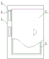
Fig. 1 is a schematic structural diagram of the present invention; fig. 2 is an enlarged view of the top view of fig. 1.
Detailed Description
In order to make the objects, technical solutions and advantages of the embodiments of the present invention clearer, the embodiments of the present invention will be clearly and completely described below with reference to the accompanying drawings in the embodiments of the present invention, and it is obvious that the described embodiments are some, but not all, embodiments of the present invention. Based on the embodiments in the present invention, all other embodiments obtained by a person skilled in the art without creative efforts belong to the protection scope of the present invention.
An electric device for water supply engineering construction comprises a box body 1, a box door 2 is hinged on the left side of the front of the box body 1, a clamping groove 3 is formed in the left side of the upper portion of the front of the box body 1, a clamping strip 4 is fixedly installed on the left side of the upper portion of the box door 2 and made of elastic materials, the clamping strip 4 can be inserted into the clamping groove 3, a circle of light bar 5 is arranged in the box body 1, a groove 6 is formed in the upper portion of the front of the box body 1, the cross section of the rear portion of the groove 6 is dovetail-shaped, a first electrode block 7 with a dovetail-shaped cross section is fixedly installed on the left side of the inner back of the groove 6, a spring 8 is fixedly connected on the right side of the inner back of the groove 6, the left end of the spring 8 is fixedly connected with the right side of a second electrode block 9 with a dovetail-shaped cross section, the second electrode block 9 can move along the groove 6, the first, be equipped with power 11 in the chamber door 2, second electrode block 9 has with power 11 to be connected, and first electrode block 7 has with lamp strip 5 to be connected. Use the utility model discloses the time, open chamber door 2, 2 removal of chamber door drive connecting rod 10 and remove, 10 right-hand members of connecting rod remove and drive second electrode piece 9 and remove left along recess 6, 2 open back card strip 4 completely of chamber door and insert in draw-in groove 3, thereby fix chamber door 2 in box 1 preceding, second electrode piece 9 and 7 contact circular telegrams of first electrode piece this moment, power 11 supplies power for lamp strip 5, lamp strip 5 throws light on to the box 1 in, the person of facilitating the use overhauls, close chamber door 2 after the use, 8 pulling second electrode pieces 9 of spring remove right when chamber door 2 closes, spring 8 can the person of assisting the user close chamber door 2, high convenience and fast, time saving and labor saving. The utility model discloses simple structure, convenient to use can fix chamber door 2, and the person of facilitating the use overhauls, opens chamber door 2 and switches on promptly, can provide sufficient illumination for the maintenance, and the operation of being convenient for overhaul closes chamber door 2 and cuts off the power supply promptly, prevents that the user from forgetting to close the lamp strip, avoids extravagant electric energy, and energy-conserving effect is obvious.
Specifically, improper installation of the position of lamp strip 5 can cause and form large tracts of land shade below the electrical components, can't play the due effect of illumination, lamp strip 5 described in this embodiment be located 1 inner wall front side of box. The lamp strip 5 is located 1 inner wall front side of box, by preceding back lighting, and the illuminance is even, can effectively eliminate the shadow.
Specifically, its inside component produced a large amount of heats when box 1 used, need dispel the heat, this embodiment the box 1 left and right sides set up the ventilation window respectively, the ventilation window position on left side is higher than the ventilation window position on right side, equal fixed mounting dust screen in the ventilation window. The left side ventilation window is higher in position, and the right side ventilation window is lower to ventilation cooling is convenient for.
Further, card strip 4 inserts in draw-in groove 3 to fix chamber door 2 in 1 preceding at the box, this embodiment 1 preceding middle part fixed mounting magnetic sheet of box, 2 middle part left sides fixed mounting iron sheet of chamber door, the iron sheet adsorbs with the magnetic sheet mutually. The iron sheet and the magnetic sheet are adsorbed, so that the auxiliary fixing effect can be achieved, and the fixing effect is better.
Furthermore, there is the gap between chamber door 2 and the box 1, advances grey intake easily and intakes, 2 back outsides fixed mounting sealing strips of chamber door, the sealing strip contacts with 1 inner wall of box. The sealing strip plugs up the gap between chamber door 2 and the box 1, effective dustproof and waterproof.
Furthermore, when the user opens the door 2, a force application point is needed, the handle is adopted in the traditional force application point, but the handle is exposed, and the user can feel pain when the user accidentally bumps into the door, in the embodiment, the finger groove is formed in the right side of the front part of the middle part of the door 2. The finger groove is formed in the front right side of the middle of the box door 2, so that the box door 2 is convenient to open, and the use safety is improved.
Finally, it should be noted that: the above embodiments are only used to illustrate the technical solution of the present invention, and not to limit it; although the present invention has been described in detail with reference to the foregoing embodiments, it should be understood by those skilled in the art that: the technical solutions described in the foregoing embodiments may still be modified, or some technical features may be equivalently replaced; such modifications and substitutions do not depart from the spirit and scope of the present invention in its corresponding aspects.
Claims (6)
1. Electric installation is used in water supply engineering construction, its characterized in that: the box comprises a box body (1), a box door (2) is hinged on the left front side of the box body (1), a clamping groove (3) is formed in the left front upper side of the box body (1), a clamping strip (4) is fixedly installed on the left upper side of the box door (2), the clamping strip (4) can be inserted into the clamping groove (3), a circle of light bar (5) is arranged in the box body (1), a groove (6) is formed in the upper front side of the box body (1), the section of the rear part of the groove (6) is in a dovetail shape, a first electrode block (7) with a dovetail-shaped section is fixedly installed on the left inner back side of the groove (6), a spring (8) is fixedly connected on the inner right side of the groove (6), the left end of the spring (8) is fixedly connected on the right side of a second electrode block (9) with a dovetail-shaped section, the second electrode block (9) can move along the groove (6), the first electrode block (7) and the second electrode block (9, the left end of the connecting rod (10) is hinged to the left side of the upper back of the box door (2), a power supply (11) is arranged in the box door (2), the second electrode block (9) is connected with the power supply (11), and the first electrode block (7) is connected with the lamp strip (5).
2. The electric device for water supply engineering construction according to claim 1, characterized in that: the lamp strip (5) is positioned on the front side of the inner wall of the box body (1).
3. The electric device for water supply engineering construction according to claim 1, characterized in that: the left side and the right side of the box body (1) are respectively provided with a ventilation window, the position of the ventilation window at the left side is higher than that of the ventilation window at the right side, and dust screens are fixedly installed in the ventilation windows.
4. The electric device for water supply engineering construction according to claim 1, characterized in that: the magnetic sheet is fixedly arranged in the middle of the front of the box body (1), the iron sheet is fixedly arranged on the left side of the middle of the box door (2), and the iron sheet and the magnetic sheet are adsorbed.
5. The electric device for water supply engineering construction according to claim 1, characterized in that: and a sealing strip is fixedly arranged on the outer side of the back surface of the box door (2), and the sealing strip is in contact with the inner wall of the box body (1).
6. The electric device for water supply engineering construction according to claim 1, characterized in that: the right side in front of the middle part of the box door (2) is provided with a finger groove.
Priority Applications (1)
| Application Number | Priority Date | Filing Date | Title |
|---|---|---|---|
| CN201920210407.5U CN209994692U (en) | 2019-02-18 | 2019-02-18 | Electric device for water supply engineering construction |
Applications Claiming Priority (1)
| Application Number | Priority Date | Filing Date | Title |
|---|---|---|---|
| CN201920210407.5U CN209994692U (en) | 2019-02-18 | 2019-02-18 | Electric device for water supply engineering construction |
Publications (1)
| Publication Number | Publication Date |
|---|---|
| CN209994692U true CN209994692U (en) | 2020-01-24 |
Family
ID=69288718
Family Applications (1)
| Application Number | Title | Priority Date | Filing Date |
|---|---|---|---|
| CN201920210407.5U Expired - Fee Related CN209994692U (en) | 2019-02-18 | 2019-02-18 | Electric device for water supply engineering construction |
Country Status (1)
| Country | Link |
|---|---|
| CN (1) | CN209994692U (en) |
Cited By (1)
| Publication number | Priority date | Publication date | Assignee | Title |
|---|---|---|---|---|
| CN111193208A (en) * | 2020-03-13 | 2020-05-22 | 内蒙古德广电气股份有限公司 | Combined high-voltage complete set distribution control box |
-
2019
- 2019-02-18 CN CN201920210407.5U patent/CN209994692U/en not_active Expired - Fee Related
Cited By (2)
| Publication number | Priority date | Publication date | Assignee | Title |
|---|---|---|---|---|
| CN111193208A (en) * | 2020-03-13 | 2020-05-22 | 内蒙古德广电气股份有限公司 | Combined high-voltage complete set distribution control box |
| CN111193208B (en) * | 2020-03-13 | 2022-01-18 | 内蒙古德广电气股份有限公司 | Combined high-voltage complete set distribution control box |
Similar Documents
| Publication | Publication Date | Title |
|---|---|---|
| CN209994692U (en) | Electric device for water supply engineering construction | |
| CN111600211B (en) | Assembled energy-saving switch cabinet | |
| CN214478935U (en) | Low-voltage switch cabinet convenient to overhaul | |
| CN205092428U (en) | Multi -functional regulator cubicle | |
| CN212033539U (en) | Low-voltage terminal control box | |
| CN212745217U (en) | Smoke-proof fire-proof valve with good stability performance | |
| CN209149725U (en) | A kind of three-dimensional dual surface LED advertisement machine | |
| CN210246023U (en) | Electric appliance control cabinet convenient to automatically dissipate heat | |
| CN204349244U (en) | Control flow cabinet | |
| CN206758850U (en) | A kind of protection type distribution box | |
| CN207705666U (en) | A kind of power distribution cabinet with illumination functions | |
| CN206948249U (en) | A kind of long margin frame of solar energy component and the attachment structure of short frame | |
| CN218217985U (en) | Equipment protection device | |
| CN204116846U (en) | Power supply smart controller | |
| CN211457636U (en) | Dustproof outdoor regulator cubicle | |
| CN212543163U (en) | Energy-saving control power distribution device | |
| CN209742632U (en) | Window glass with projection function | |
| CN215167647U (en) | Energy-conserving building concrete installation door | |
| CN203466457U (en) | Rainproof, dustproof and heat-radiating power distribution cabinet | |
| CN218678102U (en) | Low-power distribution box with high sealing performance | |
| CN214849576U (en) | High-reliability multi-source coordination power distribution cabinet capable of long-term operation | |
| CN209016505U (en) | A kind of interior rail mounted power distribution cabinet | |
| CN217010349U (en) | Three-phase combined overvoltage protector | |
| CN107995827A (en) | A kind of illuminating energy-saving controller | |
| CN215185288U (en) | Power equipment cabinet for outdoor installation and use |
Legal Events
| Date | Code | Title | Description |
|---|---|---|---|
| GR01 | Patent grant | ||
| GR01 | Patent grant | ||
| CF01 | Termination of patent right due to non-payment of annual fee |
Granted publication date: 20200124 Termination date: 20210218 |
|
| CF01 | Termination of patent right due to non-payment of annual fee |