CN209949578U - Full-automatic online board separator - Google Patents
Full-automatic online board separator Download PDFInfo
- Publication number
- CN209949578U CN209949578U CN201920434755.0U CN201920434755U CN209949578U CN 209949578 U CN209949578 U CN 209949578U CN 201920434755 U CN201920434755 U CN 201920434755U CN 209949578 U CN209949578 U CN 209949578U
- Authority
- CN
- China
- Prior art keywords
- plate
- axis
- driving
- mounting
- belt
- Prior art date
- Legal status (The legal status is an assumption and is not a legal conclusion. Google has not performed a legal analysis and makes no representation as to the accuracy of the status listed.)
- Expired - Fee Related
Links
Images


Landscapes
- Details Of Cutting Devices (AREA)
Abstract
The utility model discloses a full-automatic online board separator, including the frame, still include: the feeding mechanism comprises a distance adjusting mechanism arranged on the rack, a first plate conveying belt and a second plate conveying belt parallel to the first plate conveying belt; the clamping mechanism comprises a three-axis movement mechanism arranged on the rack and a clamping device in driving connection with the three-axis movement mechanism; the three-axis movement mechanism drives the clamping device to move along X, Y, Z three-axis directions; the clamping device is positioned between the second plate conveying conveyer belt and the first plate conveying conveyer belt; the plate separating mechanism is positioned at the discharge end of the feeding mechanism and comprises an upper cutter mechanism and a lower cutter mechanism positioned below the upper cutter mechanism, and the upper cutter mechanism is driven by a driving mechanism to slide in a reciprocating manner; the upper cutter mechanism is also provided with a pressing device; the lower cutter mechanism is driven by a lifting mechanism to move up and down; and the discharging mechanism is arranged on the rack and is positioned on one side of the plate dividing mechanism.
Description
Technical Field
The utility model relates to a board separator technical field especially relates to a full-automatic online board separator.
Background
The board separator is generally referred to as a PCB separator, that is, a circuit board separator. Board separation machines are widely used in the electronic product manufacturing industry. Because the traditional manual plate folding method has strong stress and serious influence on the product quality, the manual plate folding is basically replaced by machine plate splitting.
The Chinese patent with the application number of 201410360628.2 discloses a manual PCB board separator, which comprises an upper guide rail, a lower support beam, two upright posts connecting the two ends of the upper guide rail and the lower support beam, and a flat plate of the support upright posts; a cutter is arranged between the upper guide rail and the lower support beam, the cutter is suspended with the upper guide rail through a connecting piece, and the top end of the connecting piece is clamped in a chute of the upper guide rail; the lower supporting beam is provided with a cutter seat corresponding to the cutter and a working platform; one end of the sliding chute is connected with a spring arranged along the direction of the sliding chute, the other end of the spring is connected with a soft impact block, and the spring and the soft impact block both fall into the sliding chute and are used for impacting the top end of the connecting piece to enable the connecting piece to rebound; the other end of the sliding groove is provided with a first magnet block used for preventing collision after the top end of the connecting piece rebounds, a second magnet block is arranged on one surface of the top end of the connecting piece corresponding to the first magnet block, and the magnetism of the two opposite surfaces of the first magnet block and the second magnet block is the same.
When the board dividing machine is used, an operator places a circuit board to be divided on the cutter seat, then slides the cutter along the guide rail, and completes board dividing operation of the circuit board along with the sliding of the cutter. The working mode of manually placing the plate has the defects of inaccurate cutting position, low automation degree, low working efficiency and insecurity.
Therefore, it is desirable to provide a fully automatic online board separator to solve the deficiencies of the prior art.
SUMMERY OF THE UTILITY MODEL
The utility model aims to provide a pair of full-automatic online board separator aims at solving the technical problem that board separator work efficiency among the prior art is low.
In order to solve the technical problem, the utility model discloses a technical scheme as follows:
the utility model provides a full-automatic online board separator, includes the frame, still includes:
the feeding mechanism comprises a distance adjusting mechanism arranged on the rack, a first plate conveying belt and a second plate conveying belt parallel to the first plate conveying belt; the distance adjusting mechanism is in driving connection with the first plate conveying conveyer belt and/or the second plate conveying conveyer belt;
the clamping mechanism comprises a three-axis movement mechanism arranged on the rack and a clamping device in driving connection with the three-axis movement mechanism; the three-axis movement mechanism drives the clamping device to move along X, Y, Z three-axis directions; the clamping device is positioned between the second plate conveying conveyer belt and the first plate conveying conveyer belt;
the plate dividing mechanism is positioned at the discharge end of the feeding mechanism and comprises an upper cutter mechanism and a lower cutter mechanism positioned below the upper cutter mechanism, and the upper cutter mechanism is driven by a driving mechanism to slide in a reciprocating manner; a pressing device is also arranged on the upper cutter mechanism; the lower cutter mechanism is driven by a lifting mechanism to move up and down; and
and the discharging mechanism is arranged on the rack and positioned on one side of the plate dividing mechanism.
Preferably, the clamping device comprises a mounting plate, a first air cylinder fixedly arranged on the mounting plate, and an upper clamping plate and a lower clamping plate which are respectively connected with the mounting plate in a rotating manner; the first air cylinder drives the upper clamping plate and the lower clamping plate to do opening and closing actions.
Preferably, the mounting plate extends along the horizontal direction to form an extension part; a piston rod of the first cylinder penetrates the extending part upwards and is connected with the end part of the upper clamping plate; the end part of the extension part extends to the vertical direction to form a connecting part; the upper clamping plate and the lower clamping plate are respectively provided with a rotating shaft sleeve in an integrated forming way; the rotating shaft penetrates through the rotating shaft sleeve and is rotatably connected with the connecting part; the two rotating sleeves are respectively provided with a tooth-shaped part, and the two tooth-shaped parts are mutually meshed.
Preferably, the three-axis movement mechanism comprises an X-axis movement mechanism, a Y-axis movement mechanism and a Z-axis movement mechanism; the X-axis movement mechanism comprises an X-axis slide rail fixedly arranged on the rack, an X-axis slide carriage connected with the X-axis slide rail in a sliding manner and an X-axis driving device for driving the X-axis slide carriage to slide; the Y-axis movement mechanism comprises a Y-axis driving mechanism arranged on the X-axis sliding seat and a Y-axis sliding seat in driving connection with the Y-axis driving mechanism; the Z-axis movement mechanism comprises a Z-axis driving device fixedly arranged on the Y-axis sliding seat and a Z-axis sliding seat in driving connection with the Z-axis driving device; the mounting plate is fixedly arranged on the Z-axis sliding seat.
Preferably, the lower cutter mechanism comprises a fixed seat fixedly arranged on the rack, a blade mounting seat connected with the fixed seat in a sliding manner, and a lower cutter fixedly arranged on the blade mounting seat.
Preferably, the lifting mechanism comprises a second cylinder, a plurality of swing rods and a plurality of vertical turntables corresponding to the swing rods; a rotating shaft is arranged at the center of a circle at one side of the rotating disc, and a rolling bearing eccentric to the rotating shaft is arranged at the other side of the rotating disc; the blade mounting seat is provided with a strip-shaped concave part, and the rolling bearings respectively extend into the strip-shaped concave part; the second cylinder drives the swing rod to swing; the swing rods respectively penetrate through the rotating shafts from the radial direction.
Preferably, the number of the rotary disc and the number of the swing rods are two respectively; the two rotary tables are respectively positioned at two sides of the blade mounting seat; the top ends of the two swing rods are respectively and rotatably connected with two ends of a connecting rod; and a piston rod of the second cylinder is rotatably connected with the bottom end of one of the swing rods.
Preferably, the upper cutter mechanism comprises a portal frame and an upper cutter arranged on the portal frame; the driving mechanism comprises a first motor arranged on the gantry, first driving wheels arranged at two ends of the top of the gantry and a first driving belt sleeved on the first driving wheels; the upper cutter comprises a mounting sliding seat in sliding connection with the portal frame and an upper circular cutter rotationally arranged on the mounting sliding seat; the mounting sliding seat is fixedly connected with the first transmission belt; the upper circular knife and the lower cutting knife are in the same plane; the pressing device comprises a third air cylinder fixedly arranged on the mounting sliding seat and a pressing plate arranged on a piston rod of the third air cylinder.
Preferably, the discharging mechanism comprises a discharging conveying belt arranged on the rack and a discharging plate arranged obliquely; the upper side of the discharging plate is positioned at one side of the lower cutter mechanism, and the lower side of the discharging plate is positioned above the discharging conveying belt.
Preferably, the distance adjusting mechanism comprises a second motor fixedly arranged on the rack, a first screw rod connected with an output shaft of the second motor, a first nut piece screwed with the first screw rod, and a sliding table fixedly connected with the first nut piece; the first plate conveying conveyer belt comprises a first mounting bracket, a third motor fixedly arranged on the first mounting bracket, second driving wheels respectively arranged at two ends of the first mounting bracket, and a second driving belt sleeved on the second driving wheels; the second transmission belt is in driving connection with the third motor; the first mounting bracket is fixedly arranged on the rack; the second plate conveying conveyer belt comprises a second mounting bracket, a fourth motor fixedly arranged on the second mounting bracket, third driving wheels respectively arranged at two ends of the second mounting bracket and a third driving belt sleeved on the third driving wheels; the third transmission belt is in driving connection with the fourth motor; the second mounting bracket is fixedly connected with the sliding table; and two ends of the first mounting bracket or the second mounting bracket are respectively provided with a first photoelectric sensor.
The utility model has the advantages that: when the full-automatic online board separator works, two sides of a circuit board are respectively placed on a first board conveying belt and a second board conveying belt and conveyed forwards to the position below a pressing device, the pressing device presses the circuit board tightly, a three-axis movement mechanism drives a clamping device to move upwards firstly and then move forwards to one side of the circuit board, the clamping device clamps the circuit board, and the pressing device resets; the lifting mechanism drives the lower cutter mechanism to move upwards until the lower cutter mechanism abuts against the bottom of the circuit board; the driving mechanism drives the upper cutter mechanism to reciprocate, after the upper cutter mechanism scratches the circuit board, the circuit board is divided once, then the three-axis movement mechanism drives the clamping device to move forwards for a certain distance, and the upper cutter mechanism continues dividing the circuit board until the whole circuit board is divided; the full-automatic online board separator has the advantages of high automation degree, labor saving, high working efficiency, high board separating precision and high safety.
Drawings
In order to more clearly illustrate the technical solutions of the embodiments of the present invention, the drawings required for the embodiments or the prior art descriptions will be briefly introduced below, and it is obvious that the drawings in the following description are only some embodiments of the present invention, and it is obvious for those skilled in the art to obtain other drawings without inventive labor.
Fig. 1 is a perspective view of a fully automatic online plate separator according to an embodiment of the present invention;
fig. 2 is a top view of a fully automatic online board separator according to an embodiment of the present invention;
fig. 3 is a schematic structural diagram of a feeding mechanism provided in an embodiment of the present invention;
fig. 4 is another schematic structural diagram of a feeding mechanism provided in an embodiment of the present invention;
fig. 5 is a schematic structural view of a material clamping mechanism provided in the embodiment of the present invention;
fig. 6 is another schematic structural diagram of the material clamping mechanism according to the embodiment of the present invention;
fig. 7 is a schematic structural view of a clamping device according to an embodiment of the present invention;
fig. 8 is a rear view of the plate dividing mechanism according to the embodiment of the present invention;
fig. 9 is a front view of the plate dividing mechanism according to the embodiment of the present invention;
fig. 10 is a rear view of a lifting mechanism provided in an embodiment of the present invention;
fig. 11 is a front view of a lifting mechanism according to an embodiment of the present invention;
fig. 12 is a schematic structural diagram of a discharging mechanism provided in the embodiment of the present invention.
Detailed Description
In order to make the object, technical solution and technical effect of the present invention more clearly understood, the present invention will be further described with reference to the following embodiments. It should be understood that the specific embodiments described herein are for purposes of illustration only and are not intended to limit the invention.
In one embodiment of the present invention, as shown in fig. 1-2, a fully automatic online plate separator includes a frame 1, a feeding mechanism 2, a clamping mechanism 3, a plate separator 4, and a discharging mechanism 5.
The feeding mechanism 2 comprises a distance adjusting mechanism 21 arranged on the rack 1, a first plate conveying belt 22 and a second plate conveying belt 23 parallel to the first plate conveying belt 22. The distance adjusting mechanism 21 is in driving connection with the first plate conveying belt 22 and/or the second plate conveying belt 23. The feeding mechanism 2 is used for automatic feeding, and the working efficiency is higher.
The clamping mechanism 3 comprises a three-axis movement mechanism 31 arranged on the rack 1 and a clamping device 32 in driving connection with the three-axis movement mechanism 31. The three-axis movement mechanism 31 drives the clamping device 32 to move along X, Y, Z three-axis directions. The clamping device 32 is located between the second plate conveyor belt 23 and the first plate conveyor belt 22.
The plate dividing mechanism 4 is located at the discharge end of the feeding mechanism 2 and comprises an upper cutter mechanism 41 and a lower cutter mechanism 42 located below the upper cutter mechanism 41, and the upper cutter mechanism 41 is driven by a driving mechanism 6 to slide in a reciprocating manner. The upper cutter mechanism 41 is further provided with a pressing device 7. The lower cutter mechanism 42 is driven by a lifting mechanism 8 to move up and down.
The discharging mechanism 5 is arranged on the frame 1 and is positioned on one side of the plate dividing mechanism 4.
When the full-automatic online board separator works, two sides of a circuit board are respectively placed on the first board conveying belt 22 and the second board conveying belt 23 and conveyed forwards to the position below the pressing device 7, the pressing device 7 presses the circuit board tightly, the three-axis movement mechanism 31 drives the clamping device 32 to move upwards firstly and then move forwards to one side of the circuit board, the clamping device 32 clamps the circuit board, and the pressing device 7 resets. The lifting mechanism 8 drives the lower cutter mechanism 42 to move upwards until the lower cutter mechanism 42 abuts against the bottom of the circuit board. The driving mechanism 6 drives the upper cutter mechanism 41 to reciprocate, after the upper cutter mechanism 41 scratches the circuit board, the circuit board is divided once, then the three-axis movement mechanism 31 drives the clamping device 32 to move forward for a certain distance, and the upper cutter mechanism 41 continues dividing the circuit board until the whole circuit board is divided. The full-automatic online board separator has the advantages of high automation degree, labor saving, high working efficiency, high board separating precision and high safety.
In another embodiment of the present invention, as shown in fig. 7, the clamping device 32 of the fully automatic on-line board separator is provided to comprise a mounting plate 321, a first cylinder 322 fixed on the mounting plate 321, and an upper clamping plate 323 and a lower clamping plate 324 rotatably connected to the mounting plate 321, respectively. The first cylinder 322 drives the upper plate 323 and the lower plate 324 to open and close.
In another embodiment of the present invention, as shown in fig. 7, the mounting plate 321 of the fully automatic in-line board separator is provided to extend along a horizontal direction to form an extension 3211. A piston rod of the first cylinder 322 extends upward through the extension 321 and is connected to an end of the upper plate 323. An end of the extending portion 3211 extends in a vertical direction to form a connecting portion 3212. The upper clamp plate 323 and the lower clamp plate 324 are respectively provided with a rotating shaft sleeve 3231, 3241 in an integrated manner. The rotating shaft passes through the rotating shaft sleeves 3231 and 3241 respectively and is connected with the connecting part 3212 in a rotating way. The two rotating sleeves 3231, 3241 are provided with teeth 3232, 3242, respectively. The two teeth 3232, 3242 engage with each other. Specifically, the working principle of the clamping device 32 is as follows: when the piston rod of the first air cylinder 322 extends and contracts, the upper clamping plate 323 is driven to rotate, and when the upper clamping plate 323 rotates, the lower clamping plate 324 is driven to rotate reversely through the tooth parts 3232 and 3242, so that the included angle between the clamping surfaces of the upper clamping plate 323 and the lower clamping plate 324 is increased or decreased. The clamping device 32 replaces the manual plate holding mode, so that the working efficiency is improved, and the clamping is more stable. When the plate is fed, the movement distance of the three-axis movement mechanism 31 is controlled, so that more accurate plate feeding can be realized, and the plate dividing precision is finally improved.
In another embodiment of the present invention, as shown in fig. 5 and 6, the three-axis moving mechanism 31 of the fully automatic online plate separator is provided to include an X-axis moving mechanism 33, a Y-axis moving mechanism 34, and a Z-axis moving mechanism 35. The X-axis moving mechanism 33 includes an X-axis slide rail 331 fixed on the frame 1, an X-axis slide carriage 332 connected to the X-axis slide rail 331 in a sliding manner, and an X-axis driving device 333 for driving the X-axis slide carriage 332 to slide. The top surface of the rack 1 is fixedly provided with an X-axis shell 11 extending downwards, the X-axis driving device 333 comprises an X-axis motor 3331 fixedly arranged on the X-axis shell 11, an X-axis screw 3332 connected with an output shaft of the X-axis motor 3331 and an X-axis nut 3333 screwed with the X-axis screw 3332, and the X-axis nut 3333 is fixedly connected with the X-axis sliding seat 332. An X-axis sliding block 334 which is connected with the X-axis sliding rail 331 in a sliding manner is fixedly arranged at the bottom of the X-axis sliding seat 332. Specifically, when the X-axis moving mechanism 33 works, the X-axis motor 3331 drives the X-axis screw 3332 to rotate, and the X-axis screw 3332 drives the X-axis sliding base 332 to slide along the X-axis sliding rail 331 through the X-axis nut 3333.
The Y-axis moving mechanism 34 includes a Y-axis driving mechanism 341 disposed on the X-axis sliding base 332 and a Y-axis sliding base 342 drivingly connected to the Y-axis driving mechanism 341. The X-axis slide carriage 332 is fixedly provided with a Y-axis housing 343. The Y-axis driving mechanism 341 includes a Y-axis motor 3411 fixed to the Y-axis housing 343, a Y-axis screw 3412 connected to an output shaft of the Y-axis motor 3411, and a Y-axis nut 3413 screwed to the Y-axis screw 3412, and the Y-axis slide 342 is fixedly connected to the Y-axis nut 3413. Specifically, when the Y-axis moving mechanism 34 is operated, the Y-axis motor 3411 drives the Y-axis screw 3412 to rotate, and the Y-axis screw 3412 drives the Y-axis slide 342 to move in the Y-axis direction through the Y-axis nut 3413.
The Z-axis moving mechanism 35 includes a Z-axis driving device 351 fixed on the Y-axis slide carriage 342 and a Z-axis slide carriage 352 drivingly connected to the Z-axis driving device 351. The mounting plate 321 is fixed on the Z-axis slide 352. The Z-axis driving device 351 is a fourth cylinder, a Z-axis sliding rail is fixedly arranged on a cylinder body of the fourth cylinder, and a Z-axis sliding block slidably connected with the Z-axis sliding rail is arranged on the Z-axis sliding seat 352. Specifically, the working principle of the Z-axis movement mechanism 35 is as follows: when the piston rod of the Z-axis driving device 351 extends or contracts, the Z-axis slider 352 is driven to slide in the Z-axis direction.
In another embodiment of the present invention, as shown in fig. 8-11, the lower cutter mechanism 42 of the fully automatic on-line board separator provided comprises a fixing seat 421 fixed on the frame 1, a blade mounting seat 422 slidably connected to the fixing seat 421, and a lower cutter 423 fixed on the blade mounting seat 422, wherein the lower cutter 423 is a straight cutter. Specifically, a third guide rail 4211 extending in the vertical direction is fixedly arranged on the fixed seat 421, and a third slider 4222 slidably connected with the third guide rail 4211 is fixedly arranged on the blade mounting seat 422.
In another embodiment of the present invention, as shown in fig. 8-11, said lifting mechanism 8 of the fully automatic on-line board separator is provided to comprise a second cylinder 81, a plurality of swing rods 82, 82 ' and a plurality of vertical turntables 83, 83 ' corresponding to said swing rods 82, 82 '. The center of one side of the rotary disc 83, 83 ' is provided with a rotary shaft 84, 84 ', and the other side is provided with a rolling bearing 85, 85 ' eccentric to the rotary shaft. The blade mounting seat 422 is provided with strip-shaped concave portions 4221, 4221'. The rolling bearings 85, 85 'each project into the respective strip-shaped recess 4221, 4221'. The second cylinder 81 drives the swing rods 82 and 82' to swing. The rocker levers 82, 82 'pass through the rotary shafts 84, 84', respectively, from the radial direction. The strip-shaped concave parts 4221 and 4221' are strip-shaped holes or strip-shaped grooves.
In another embodiment of the present invention, as shown in fig. 8 to 11, the number of the rotating discs 83, 83 'and the swinging rods 82, 82' of the fully automatic on-line plate separator is two. The two rotating discs 83, 83' are respectively located at two sides of the blade mounting seat 422. The top ends of the two swing rods 82 and 82' are respectively rotatably connected with two ends of a connecting rod 86. The piston rod of the second cylinder 81 is rotatably connected with the bottom end of one of the swing rods 82. Specifically, the working principle of the lifting mechanism 8 is as follows: when the piston rod of the second cylinder 81 extends and retracts, one of the swing rods 82 is driven to swing, the swing rod 82 drives the other swing rod 82 ' to swing through the connecting rod 86, the swing rods 82 and 82 ' respectively drive the rotating shafts 84 and 84 ' to rotate through the rotating shafts 84 and 84 ' when swinging, when the rotating shafts 84 and 84 ' rotate, the height positions of the rolling bearings 85 and 85 ' are changed, and the rolling bearings 85 and 85 ' drive the blade mounting seat 422 to slide in the vertical direction along the third guide rail 4211, so that the lower cutter 423 moves up and down. When the board is fed and separated, the lifting mechanism 8 drives the lower cutter 423 to move upwards and abut against the bottom surface of the circuit board, and after the board is separated, the lifting mechanism 8 drives the lower cutter 423 to move downwards and reset. The lifting mechanism 8 has the advantage of high working stability.
In another embodiment of the present invention, as shown in fig. 8-11, the upper cutter mechanism 41 of the fully automatic in-line plate separator is provided to include a gantry 411 and an upper cutter 412 disposed on the gantry 411. The driving mechanism 6 comprises a first motor 61 arranged on the portal frame 411, first driving wheels 62 arranged at two ends of the top of the portal frame 411, and a first driving belt 63 sleeved on the first driving wheels 62. The upper tool 412 includes a mounting slide 4121 slidably connected to the gantry 411, and an upper circular knife 4122 rotatably disposed on the mounting slide 4121. The mounting slide 4121 is fixedly connected to the first belt 63. Specifically, the mounting slide 4121 is fixedly connected to the first driving belt 63 through a synchronous buckle; the first driving wheel 62 is a belt pulley, and the first driving belt 63 is a belt. And a second guide rail 4111 for slidably connecting the mounting sliding seat 4121 is arranged on the gantry 411. The driving mechanism 6 has the working principle that: the first motor 61 drives one of the first transmission wheels 62 to rotate, the first transmission wheel 62 drives the first transmission belt 63 to move, and the first transmission belt 63 drives the mounting slide 4121 to slide in a reciprocating manner, so that the upper circular knife 4122 moves in a reciprocating manner.
The upper circular knife 4122 and the lower cutting knife 423 are in the same plane. The pressing device 7 comprises a third air cylinder 71 fixedly arranged on the mounting sliding seat 4121 and a pressing plate 72 arranged on a piston rod of the third air cylinder 71. When the circuit board is conveyed to the lower part of the pressing device 7, the third cylinder 71 drives the pressing plate 72 to press down on the circuit board, so as to fix the circuit board, and the circuit board is conveniently clamped by the clamping device 32.
In another embodiment of the present invention, as shown in fig. 12, the discharging mechanism 5 of the fully automatic on-line plate separator is provided to include a discharging conveyer belt 51 disposed on the frame 1 and a discharging plate 52 disposed obliquely. The upper side of the stripper plate 52 is located on one side of the lower cutter mechanism 42 and the lower side thereof is located above the outfeed conveyor belt 51. The discharging conveyer belt 51 is fixedly arranged on two parallel shaft mounting plates 511 on the rack 1, a belt driving shaft 512 respectively arranged at two ends of the shaft mounting plate 511, a discharging belt 513 sleeved on the belt driving shaft 512 and a fifth motor 514 driving the belt driving shaft 512 to rotate. After the circuit board passes through the board separating mechanism 4, the product slides onto the discharging belt 513 through the discharging board 52, and the fifth motor 514 drives the discharging belt 513 to convey the product forwards through the belt driving shaft 512. And the discharging mechanism 5 is used for automatic discharging and improving the efficiency.
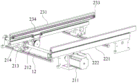
In another embodiment of the present invention, as shown in fig. 3 and 4, the distance adjusting mechanism 21 of the fully automatic online plate separator provided comprises a second motor 211 fixedly arranged on the frame 1, a first lead screw 212 connected to an output shaft of the second motor 211, a first nut member 213 screwed with the first lead screw 212, and a sliding table 214 fixedly connected to the first nut member 213. The rack 1 is provided with a first guide rail 12 for the sliding table 214 to slide, and the first guide rail 12 is perpendicular to the first plate conveying belt 22.
The first plate conveying belt 22 includes a first mounting bracket 221, a third motor 222 fixedly disposed on the first mounting bracket 221, second driving wheels 223 respectively disposed at two ends of the first mounting bracket 222, and a second driving belt 224 sleeved on the second driving wheels 223. The second belt 224 is in driving connection with the third motor 222. The first mounting bracket 221 is fixedly arranged on the rack 1. The two ends of the first mounting bracket 221 are respectively provided with a first photoelectric sensor 24, 24 ' and a first photoelectric sensor 24, 24 ', wherein after the first photoelectric sensor 24 ' at the starting end senses the circuit board, the first board conveying belt 22 and the second board conveying belt 23 work to start feeding. When the first photoelectric sensor 24 at the end senses the circuit board, the first board conveying belt 22 and the second board conveying belt 23 stop working, and board separation is started. In addition, when the first board conveying belt 22 is in operation, the third motor 222 drives the second belt 224 to convey the circuit board forward.
The second plate conveying belt 23 includes a second mounting bracket 231, a fourth motor 232 fixedly disposed on the second mounting bracket 231, third driving wheels 233 respectively disposed at two ends of the second mounting bracket 231, and a third belt 234 sleeved on the third driving wheels 233. The third belt 234 is drivingly connected to the fourth motor 232. The second mounting bracket 231 is fixedly connected with the sliding table 214. When the second board conveying belt 23 works, the fourth motor 232 drives the third belt 234 to move forward to convey the circuit board. Specifically, the third drive belt 234 is a belt.
Specifically, the distance adjusting mechanism 21 is used for adjusting the distance between the first board conveying belt 22 and the second board conveying belt 23, so that the feeding mechanism 2 can be applied to circuit boards with different widths, and the applicability is higher. The specific adjusting process is as follows: the second motor 211 drives the first lead screw 212 to rotate, the first lead screw 212 drives the sliding table 214 to slide along the first guide rail 12 through the first nut member 213, and the second mounting bracket 231 on the sliding table 214 is close to or far from the first mounting bracket 221, so that the distance between the two is adjusted.
The utility model has the advantages that: when the full-automatic online board separator works, two sides of a circuit board are respectively placed on a first board conveying belt and a second board conveying belt and conveyed forwards to the position below a pressing device, the pressing device presses the circuit board tightly, a three-axis movement mechanism drives a clamping device to move upwards firstly and then move forwards to one side of the circuit board, the clamping device clamps the circuit board, and the pressing device resets; the lifting mechanism drives the lower cutter mechanism to move upwards until the lower cutter mechanism abuts against the bottom of the circuit board; the driving mechanism drives the upper cutter mechanism to reciprocate, after the upper cutter mechanism scratches the circuit board, the circuit board completes board division for one time, then the three-axis movement mechanism drives the clamping device to continue to move forwards for a certain distance, and the upper cutter mechanism repeatedly divides the board until the whole circuit board completes board division; the full-automatic online board separator has the advantages of high automation degree, labor saving, high working efficiency, high board separating precision and high safety.
The utility model discloses not limited to above-mentioned embodiment, all adopt and the utility model discloses similar structure and method realize the utility model discloses all modes of purpose all are within the protection scope of the utility model.
Claims (10)
1. The utility model provides a full-automatic online board separator, includes the frame, its characterized in that still includes:
the feeding mechanism comprises a distance adjusting mechanism arranged on the rack, a first plate conveying belt and a second plate conveying belt parallel to the first plate conveying belt; the distance adjusting mechanism is in driving connection with the first plate conveying conveyer belt and/or the second plate conveying conveyer belt;
the clamping mechanism comprises a three-axis movement mechanism arranged on the rack and a clamping device in driving connection with the three-axis movement mechanism; the three-axis movement mechanism drives the clamping device to move along X, Y, Z three-axis directions; the clamping device is positioned between the second plate conveying conveyer belt and the first plate conveying conveyer belt;
the plate dividing mechanism is positioned at the discharge end of the feeding mechanism and comprises an upper cutter mechanism and a lower cutter mechanism positioned below the upper cutter mechanism, and the upper cutter mechanism is driven by a driving mechanism to slide in a reciprocating manner; a pressing device is also arranged on the upper cutter mechanism; the lower cutter mechanism is driven by a lifting mechanism to move up and down; and
and the discharging mechanism is arranged on the rack and positioned on one side of the plate dividing mechanism.
2. The full-automatic in-line plate separator as claimed in claim 1, wherein the clamping device comprises a mounting plate, a first cylinder fixed on the mounting plate, and an upper clamping plate and a lower clamping plate rotatably connected with the mounting plate respectively; the first air cylinder drives the upper clamping plate and the lower clamping plate to do opening and closing actions.
3. The automatic in-line board separator as claimed in claim 2, wherein the mounting plate extends horizontally to form an extension; a piston rod of the first cylinder penetrates the extending part upwards and is connected with the end part of the upper clamping plate; the end part of the extension part extends to the vertical direction to form a connecting part; the upper clamping plate and the lower clamping plate are respectively provided with a rotating shaft sleeve in an integrated forming way; the rotating shaft penetrates through the rotating shaft sleeve and is rotatably connected with the connecting part; the two rotating sleeves are respectively provided with a tooth-shaped part, and the two tooth-shaped parts are mutually meshed.
4. The full-automatic online plate separator as claimed in claim 2 or 3, wherein the three-axis motion mechanism comprises an X-axis motion mechanism, a Y-axis motion mechanism and a Z-axis motion mechanism; the X-axis movement mechanism comprises an X-axis slide rail fixedly arranged on the rack, an X-axis slide carriage connected with the X-axis slide rail in a sliding manner and an X-axis driving device for driving the X-axis slide carriage to slide; the Y-axis movement mechanism comprises a Y-axis driving mechanism arranged on the X-axis sliding seat and a Y-axis sliding seat in driving connection with the Y-axis driving mechanism; the Z-axis movement mechanism comprises a Z-axis driving device fixedly arranged on the Y-axis sliding seat and a Z-axis sliding seat in driving connection with the Z-axis driving device; the mounting plate is fixedly arranged on the Z-axis sliding seat.
5. The full-automatic online plate separator as claimed in claim 1, wherein the lower cutter mechanism comprises a fixed seat fixed on the frame, a blade mounting seat slidably connected with the fixed seat, and a lower cutter fixed on the blade mounting seat.
6. The full-automatic online plate separator as claimed in claim 5, wherein the lifting mechanism comprises a second cylinder, a plurality of swing rods and a plurality of vertical turntables corresponding to the swing rods; a rotating shaft is arranged at the center of a circle at one side of the rotating disc, and a rolling bearing eccentric to the rotating shaft is arranged at the other side of the rotating disc; the blade mounting seat is provided with a strip-shaped concave part, and the rolling bearings respectively extend into the strip-shaped concave part; the second cylinder drives the swing rod to swing; the swing rods respectively penetrate through the rotating shafts from the radial direction.
7. The full-automatic online plate separator as claimed in claim 6, wherein the number of the rotary disc and the swing link is two; the two rotary tables are respectively positioned at two sides of the blade mounting seat; the top ends of the two swing rods are respectively and rotatably connected with two ends of a connecting rod; and a piston rod of the second cylinder is rotatably connected with the bottom end of one of the swing rods.
8. The full-automatic online plate separator as claimed in claim 1, wherein the upper cutter mechanism comprises a portal frame and an upper cutter arranged on the portal frame; the driving mechanism comprises a first motor arranged on the gantry, first driving wheels arranged at two ends of the top of the gantry and a first driving belt sleeved on the first driving wheels; the upper cutter comprises a mounting sliding seat in sliding connection with the portal frame and an upper circular cutter rotationally arranged on the mounting sliding seat; the mounting sliding seat is fixedly connected with the first transmission belt; the upper circular knife and the lower cutting knife are in the same plane; the pressing device comprises a third air cylinder fixedly arranged on the mounting sliding seat and a pressing plate arranged on a piston rod of the third air cylinder.
9. The full-automatic in-line plate separator as claimed in claim 1, wherein the discharging mechanism comprises a discharging conveyer belt arranged on the frame and an obliquely arranged discharging plate; the upper side of the discharging plate is positioned at one side of the lower cutter mechanism, and the lower side of the discharging plate is positioned above the discharging conveying belt.
10. The full-automatic online plate separator as claimed in claim 1, wherein the distance adjusting mechanism comprises a second motor fixed on the frame, a first screw rod connected with an output shaft of the second motor, a first nut member screwed with the first screw rod, and a sliding table fixedly connected with the first nut member; the first plate conveying conveyer belt comprises a first mounting bracket, a third motor fixedly arranged on the first mounting bracket, second driving wheels respectively arranged at two ends of the first mounting bracket, and a second driving belt sleeved on the second driving wheels; the second transmission belt is in driving connection with the third motor; the first mounting bracket is fixedly arranged on the rack; the second plate conveying conveyer belt comprises a second mounting bracket, a fourth motor fixedly arranged on the second mounting bracket, third driving wheels respectively arranged at two ends of the second mounting bracket and a third driving belt sleeved on the third driving wheels; the third transmission belt is in driving connection with the fourth motor; the second mounting bracket is fixedly connected with the sliding table; and two ends of the first mounting bracket or the second mounting bracket are respectively provided with a first photoelectric sensor.
Priority Applications (1)
| Application Number | Priority Date | Filing Date | Title |
|---|---|---|---|
| CN201920434755.0U CN209949578U (en) | 2019-04-01 | 2019-04-01 | Full-automatic online board separator |
Applications Claiming Priority (1)
| Application Number | Priority Date | Filing Date | Title |
|---|---|---|---|
| CN201920434755.0U CN209949578U (en) | 2019-04-01 | 2019-04-01 | Full-automatic online board separator |
Publications (1)
| Publication Number | Publication Date |
|---|---|
| CN209949578U true CN209949578U (en) | 2020-01-14 |
Family
ID=69126312
Family Applications (1)
| Application Number | Title | Priority Date | Filing Date |
|---|---|---|---|
| CN201920434755.0U Expired - Fee Related CN209949578U (en) | 2019-04-01 | 2019-04-01 | Full-automatic online board separator |
Country Status (1)
| Country | Link |
|---|---|
| CN (1) | CN209949578U (en) |
Cited By (2)
| Publication number | Priority date | Publication date | Assignee | Title |
|---|---|---|---|---|
| CN113510779A (en) * | 2021-04-14 | 2021-10-19 | 杭州锦洲电子有限公司 | Printed circuit board processing technology and equipment |
| CN113939093A (en) * | 2021-10-25 | 2022-01-14 | 东莞市享达光电科技有限公司 | Flanging and plate dividing equipment |
-
2019
- 2019-04-01 CN CN201920434755.0U patent/CN209949578U/en not_active Expired - Fee Related
Cited By (3)
| Publication number | Priority date | Publication date | Assignee | Title |
|---|---|---|---|---|
| CN113510779A (en) * | 2021-04-14 | 2021-10-19 | 杭州锦洲电子有限公司 | Printed circuit board processing technology and equipment |
| CN113939093A (en) * | 2021-10-25 | 2022-01-14 | 东莞市享达光电科技有限公司 | Flanging and plate dividing equipment |
| CN113939093B (en) * | 2021-10-25 | 2023-07-21 | 东莞市享达光电科技有限公司 | Edge folding and plate separating equipment |
Similar Documents
| Publication | Publication Date | Title |
|---|---|---|
| CN203197377U (en) | Arbitrary angle sawing line | |
| CN104191886B (en) | The two-sided engraving machine of a kind of wooden door leaf | |
| CN209949578U (en) | Full-automatic online board separator | |
| CN207982547U (en) | A kind of razor blade Full-automatic welding equipment | |
| CN110696099A (en) | Double-end longitudinal saw device | |
| CN106965253A (en) | A kind of photo frame cornering machine of full-automatic double-ended cutting | |
| CN111761661A (en) | Bamboo-wood fiberboard cutting device and working method thereof | |
| CN110370401B (en) | Automatic fixed-length sawing and sorting device for conical round materials | |
| CN108326977B (en) | Feeding device of sheet processing equipment | |
| CN204148636U (en) | The quick blank cutter of heavy-load type aluminium alloy | |
| CN207915674U (en) | A kind of multifunctional wood board machining production line | |
| CN214561565U (en) | Preferred push rod fine cutting saw | |
| CN211053906U (en) | Positioning structure in panel processing saw | |
| CN112872612B (en) | Laser cutting mechanism | |
| CN211250341U (en) | Double-end longitudinal saw device | |
| CN210999128U (en) | Double-end horizontal saw device | |
| CN109834772B (en) | Numerical control sawing and milling machine | |
| CN113601033B (en) | Automatic positioning and cutting device and method for linear bearing pipe fitting | |
| CN219945408U (en) | Automatic unloader of five machining centers | |
| CN212146816U (en) | Wood cutting device | |
| CN219818962U (en) | Board edge cutting machine | |
| CN113146747B (en) | Numerical control line cutting saw | |
| CN112453784B (en) | Spot welding device for tweezers machining | |
| CN112355397B (en) | Photovoltaic support cutting device | |
| CN211762192U (en) | V-shaped groove cutting equipment for wood board processing |
Legal Events
| Date | Code | Title | Description |
|---|---|---|---|
| GR01 | Patent grant | ||
| GR01 | Patent grant | ||
| CF01 | Termination of patent right due to non-payment of annual fee |
Granted publication date: 20200114 Termination date: 20210401 |
|
| CF01 | Termination of patent right due to non-payment of annual fee |