Laboratory refrigerator
Technical Field
The utility model relates to a biological assay technical field especially relates to a laboratory refrigerator.
Background
The refrigerator is a refrigerating device for keeping constant low temperature, and is a civil product for keeping food or other articles in a constant low-temperature cold state. There are compressor, ice machine in the box for the cabinet or the case that freezes, have refrigerating plant's hutch, but the refrigerator in biological laboratory needs more functions, guarantees the needs of experiment, but the laboratory refrigerator of current structure, the function is single, can only refrigerate or freeze, the needs that satisfy the experiment that can not be fine.
SUMMERY OF THE UTILITY MODEL
The utility model provides a pair of laboratory refrigerator has solved the problem of function singleness.
In order to achieve the above purpose, the utility model adopts the following technical scheme:
a laboratory refrigerator comprises a shell, wherein a function box is arranged at the bottom of the shell, a freezing box is arranged above the function box, a refrigerating box is arranged above the freezing box, box covers which are rotatably connected with the shell are arranged on one sides of the refrigerating box and the freezing box, a plurality of partition plates are fixedly connected in the refrigerating box and the freezing box through bolts, the upper sides of the partition plates are slidably connected with a containing box through slide rails, one side of the containing box is fixedly connected with a nameplate frame, a temperature and humidity sensor is fixedly embedded in each partition plate, a sealing door which is rotatably connected with the shell is arranged between two partition plates in the refrigerating box, the top of the shell is fixedly connected with a liquid oxygen box through bolts, one side of the liquid oxygen box is fixedly connected with an air outlet pipe, and the other end of the air outlet pipe is fixedly connected with a plurality of communicating pipes which are fixedly connected with the refrigerating box, the outlet duct is located the upper portion of fridge, communicating pipe is connected with the flow controller valve, bolt fixedly connected with humidifier is passed through at the top of liquid oxygen case, and the output fixedly connected with drain pipe of humidifier, the other end and the outlet duct regulation of drain pipe are connected, drain pipe and outlet duct all are connected with the solenoid valve, a plurality of ultraviolet lamp of inner wall through bolt fixedly connected with of shell, one side fixedly connected with blast pipe of fridge.
Preferably, be provided with compressor and controller in the function case, solenoid valve, flow controller valve, temperature and humidity sensor, ultraviolet lamp and compressor all are connected with the controller electricity through the electric wire, and the controller adopts AFPX0L14R model controller.
Preferably, the temperature and humidity sensor is an RHT04-20 model temperature and humidity sensor, and the humidifier is an LLD-MG1 model humidifier.
Preferably, part the containing box is connected with the protective cover through the hinge rotation, the protective cover adopts the rubber material.
Preferably, one side of the box cover and one side of the sealing door are fixedly connected with sealing strips, and the sealing strips are made of rubber materials.
Preferably, one side of the function box is provided with a plurality of heat dissipation holes, and the heat dissipation holes are of a circular structure.
Preferably, the exhaust pipe is connected with a one-way valve, and the inner wall of the exhaust pipe is fixedly sleeved with a filter screen.
The utility model has the advantages that:
1. through mutually supporting of shell, containing box, protective cover, ultraviolet lamp, division board, outlet duct, drain pipe, solenoid valve, humidifier, liquid oxygen case, temperature and humidity sensor, blast pipe, case lid, freezer, function box, fridge, communicating pipe, flow controller valve, data plate frame, sealing door, can be fine freeze and refrigerate, discernment that can be convenient through the data plate and take, save time
2. Through the mutually supporting of shell, containing box, protective cover, ultraviolet lamp, division board, outlet duct, drain pipe, solenoid valve, humidifier, liquid oxygen case, temperature and humidity sensor, blast pipe, case lid, freezer, function box, fridge, communicating pipe, flow controller valve, data plate frame, sealing door, humidifier and oxygenation device's setting simultaneously guarantees biological environment's variety, guarantees biological life needs, and then guarantees biological activity, guarantees the needs of experiment.
Drawings
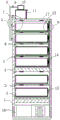
Fig. 1 is a schematic front sectional view of the present invention.
Fig. 2 is a schematic left-side sectional view of the present invention.
Fig. 3 is an enlarged schematic view of the position a of the present invention.
Fig. 4 is an enlarged schematic view of the position B of the present invention.
Reference numbers in the figures: the device comprises a shell 1, a storage box 2, a protective cover 3, an ultraviolet lamp 4, a partition plate 5, a refrigerating box 6, an air outlet pipe 7, a liquid outlet pipe 8, an electromagnetic valve 9, a humidifier 10, a liquid oxygen box 11, a temperature and humidity sensor 12, an air outlet pipe 13, a box cover 14, a freezing box 15, a functional box 16, a communicating pipe 17, a flow controller valve 18, a nameplate frame 19 and a sealing door 20.
Detailed Description
The technical solutions in the embodiments of the present invention will be described clearly and completely with reference to the accompanying drawings in the embodiments of the present invention, and it is obvious that the described embodiments are only some embodiments of the present invention, not all embodiments.
Referring to the attached drawings 1-4, a laboratory refrigerator comprises a shell 1, a functional box 16 is arranged at the bottom of the shell 1, a freezing box 15 is arranged above the functional box 16, a refrigerating box 6 is arranged above the freezing box 15, box covers 14 which are rotatably connected with the shell 1 are arranged at one sides of the refrigerating box 6 and the freezing box 15, a plurality of partition plates 5 are fixedly connected in the refrigerating box 6 and the freezing box 15 through bolts, a containing box 2 is slidably connected at the upper side of each partition plate 5 through a sliding rail, a nameplate frame 19 is fixedly connected at one side of the containing box 2, a temperature and humidity sensor 12 is fixedly embedded on each partition plate 5, a sealing door 20 which is rotatably connected with the shell 1 is arranged between the two partition plates 5 in the refrigerating box 6, a liquid oxygen box 11 is fixedly connected at the top of the shell 1 through a bolt, an air outlet pipe 7 is fixedly connected at one side of the liquid oxygen box 11, and a plurality of communicating pipes 17 which are fixedly connected with the refrigerating box 6 are, the air outlet pipe 7 is positioned at the upper part of the refrigerating box 6, the communicating pipe 17 is connected with the flow controller valve 18, the top of the liquid oxygen box 11 is fixedly connected with the humidifier 10 through bolts, the output end of the humidifier 10 is fixedly connected with the liquid outlet pipe 8, the other end of the liquid outlet pipe 8 is connected with the air outlet pipe 7 in a regulated manner, the liquid outlet pipe 8 and the air outlet pipe 7 are both connected with the electromagnetic valve 9, the inner wall of the shell 1 is fixedly connected with a plurality of ultraviolet lamps 4 through bolts, one side of the refrigerating box 6 is fixedly connected with the air outlet pipe 13, the functional box 16 is internally provided with the compressor and the controller, the electromagnetic valve 9, the flow controller valve 18, the temperature and humidity sensor 12, the ultraviolet lamp 5 and the compressor are electrically connected with the controller through electric wires, the controller adopts an AFPX0L14R model controller, the temperature and humidity, part containing box 2 rotates through the hinge and is connected with protective cover 3, and protective cover 3 adopts the rubber material, the equal fixedly connected with sealing strip in one side of case lid 14 and sealing door 20, and the sealing strip adopts the rubber material, and one side of function case 16 is provided with a plurality of louvres, and the louvre adopts circular structure, is connected with the check valve on the blast pipe 13, and the fixed filter screen that has cup jointed of inner wall of blast pipe 13.
The working principle is as follows: when the device is used, firstly, the box cover 14 and the sealing door 20 are opened, the containing box 2 is drawn out through the sliding rails, then organisms needing low-temperature preservation are placed in the containing box 2, then the box cover 14 and the sealing door 20 are closed for sealing, the controller controls the continuous work of the compressor to cool the refrigerator, meanwhile, the temperature and humidity sensor 12 monitors the temperature in the refrigerator in real time, the comparison is carried out according to the value set by the controller, the adjustment is carried out, the temperature is stabilized, then, through the work of the humidifier 10, moisture enters the refrigerating box 6 through the liquid outlet pipe 8, the gas outlet pipe 7 and the communicating pipe 17 to be adjusted, meanwhile, the controller controls the work of the electromagnetic valve 9 and the flow controller valve 18, so that oxygen in the liquid oxygen box 11 enters the refrigerating box 6 to provide oxygen, then, the gas in the liquid oxygen box is exhausted through the exhaust pipe 13, when the device is needed, the sealing door 20 and, can prevent the data plate on the data plate frame 19, the utility model discloses simple structure, convenient to use, freezing and cold-stored going on that can be fine, through the data plate can be convenient discernment and take, save time, the setting of humidifier and oxygenation device simultaneously guarantees biological environment's variety, guarantees biological life needs, and then guarantees biological activity, ensures the needs of experiment.
In the description of the present invention, it is to be understood that the terms "center", "longitudinal", "lateral", "length", "width", "thickness", "upper", "lower", "front", "rear", "left", "right", "vertical", "horizontal", "top", "bottom", "inner", "outer", "clockwise", "counterclockwise", and the like indicate orientations or positional relationships based on the orientations or positional relationships shown in the drawings, and are only for convenience of description and to simplify the description, but do not indicate or imply that the device or element referred to must have a particular orientation, be constructed and operated in a particular orientation, and therefore should not be construed as limiting the present invention.
Furthermore, the terms "first", "second" and "first" are used for descriptive purposes only and are not to be construed as indicating or implying relative importance or implicitly indicating the number of technical features indicated. Thus, a feature defined as "first" or "second" may explicitly or implicitly include one or more of that feature. In the description of the present invention, "a plurality" means two or more unless specifically limited otherwise.
The above, only be the concrete implementation of the preferred embodiment of the present invention, but the protection scope of the present invention is not limited thereto, and any person skilled in the art is in the technical scope of the present invention, according to the technical solution of the present invention and the utility model, the concept of which is equivalent to replace or change, should be covered within the protection scope of the present invention.