CN209939776U - Turnover machine - Google Patents
Turnover machine Download PDFInfo
- Publication number
- CN209939776U CN209939776U CN201920207989.1U CN201920207989U CN209939776U CN 209939776 U CN209939776 U CN 209939776U CN 201920207989 U CN201920207989 U CN 201920207989U CN 209939776 U CN209939776 U CN 209939776U
- Authority
- CN
- China
- Prior art keywords
- upset
- workstation
- support
- turnover
- workbench
- Prior art date
- Legal status (The legal status is an assumption and is not a legal conclusion. Google has not performed a legal analysis and makes no representation as to the accuracy of the status listed.)
- Active
Links
Images


Landscapes
- Attitude Control For Articles On Conveyors (AREA)
Abstract
The utility model discloses a turnover machine, including frame, workstation, upset support, fixed plate, locking support, hydraulic pressure station, spacing branch, jackshaft, upset supporting seat, upset hydro-cylinder, square bolt, locking hydro-cylinder and detection switch. The workbench of the utility model can be driven by the turnover oil cylinder to turn 90 degrees clockwise and 90 degrees anticlockwise, so that the workpiece can easily and quickly complete 90-degree turnover along with the turnover of the workbench; after the workstation overturned 90 degrees upwards, the locking hydro-cylinder can promote square bolt to inject and set up in the locking support of workstation one side, in order to realize can be to the location of workstation vertical direction, and spacing branch can carry on spacingly to the workstation of upset down, when preventing that it from overturning excessively, it can also play the effect of support to the bottom surface of work piece platform, guarantee at the in-process of clamping work piece, the workstation can not take place to rotate, the upset process of this upset machine need not artifical participation operation, it has reduced workman's intensity of labour and labour cost.
Description
Technical Field
The utility model relates to a turnover machine.
Background
The traditional large rotating devices with shells, such as motors, compressors and the like, are generally horizontally placed and assembled during assembly, and have the defects of inconvenient assembly, high assembly strength, low assembly efficiency, difficult assembly operation and the like; when the large-scale rotating device is placed and assembled in a standing mode, the assembly is convenient, but the process of placing the large-scale rotating device in a horizontal state to a vertical state after being lifted by a crane needs manual balancing points and manual alignment, and an intermediate shaft or an intermediate rotor of the large-scale rotating device is easy to collide in the placing process, namely, a plurality of workers are needed to participate in the overturning process, and when the large-scale rotating device placed in a standing mode is turned on one's side carelessly, safety accidents are easy to happen, and the problem that the potential safety hazard in use is large is solved.
Disclosure of Invention
The to-be-solved technical problem of the utility model is to provide a tilter, its workstation can clockwise overturn 90 degrees and 90 degrees anticlockwise upsets under the drive of upset hydro-cylinder, makes the work piece can swiftly accomplish 90 degrees upsets along with the upset of workstation, and its upset process need not artifical participation operation, and its greatly reduced workman's intensity of labour and the labour cost that has reduced the enterprise, and it is more convenient to use. The utility model discloses a realize through following technical scheme:
the utility model provides a turnover machine, which comprises a frame, the higher authority of frame is provided with the workstation, be provided with the upset support below the workstation bottom surface, the higher authority on both sides limit is vertical fixed plate that is provided with respectively around the frame, one side of workstation is provided with the locking support, install the hydraulic pressure station in the right part of frame, the higher authority of frame right-hand member is vertical to be provided with spacing branch, both sides are connected with the jackshaft with every fixed plate respectively around the upset support, the right-hand member of every fixed plate is provided with the upset supporting seat, every upset supporting seat is connected with the upset hydro-cylinder with the.
Preferably, a locking oil cylinder is arranged on the middle part of the rack, and a square bolt is installed at one end of the locking oil cylinder.
Preferably, a sensor or a detection switch is arranged on one side of the square bolt and used for sensing and detecting the overturning condition of the workbench.
Preferably, the overturning bracket can be driven by the overturning oil cylinder through the middle shaft to overturn upwards by a certain angle or overturn downwards by a certain angle, and the workbench can be driven by the overturning bracket to overturn upwards by a certain angle or overturn downwards by a certain angle.
Preferably, the certain angle is set to 90 degrees.
Preferably, a controller or a control system is arranged for respectively carrying out signal transmission with the locking oil cylinder, the overturning oil cylinder and the sensor or the detection switch, and the control system can adopt a PLC control system.
The utility model discloses a turnover machine, including frame, workstation, upset support, fixed plate, locking support, hydraulic pressure station, spacing branch, jackshaft, upset supporting seat, upset hydro-cylinder, square bolt, locking hydro-cylinder and detection switch. The utility model firstly places the workpiece to be overturned on the worktable which is horizontally placed, then fixes the workpiece on the worktable by using a clamp (the structure of the clamp is common knowledge and is not explained in detail here), the workpiece is fixed on the worktable by arranging an overturning bracket below the bottom surface of the worktable and vertically arranging fixed plates on the front side edge and the rear side edge of the stander respectively, each fixed plate is connected with the overturning bracket by a middle shaft and an overturning support seat arranged at the right end of each fixed plate is connected with an overturning oil cylinder on the end part of the overturning bracket, when the overturning oil cylinder is started to move rightwards, the overturning bracket connected with the overturning oil cylinder at the end part can do overturning motion upwards (namely do anticlockwise overturning) under the driving of the overturning oil cylinder, the worktable does overturning motion upwards along with the overturning of the overturning bracket, when the sensor senses that the worktable overturns upwards to 90 degrees, the sensor can automatically send a signal sensed by the sensor to the controller or the control system, the controller or the control system receives the signal and then controls the locking oil cylinder to start to operate, and when the locking oil cylinder is started, the square bolt can be pushed into the locking support, so that the workbench which is turned upwards by 90 degrees can be positioned, the phenomenon that the workbench is turned over or turned over is avoided, the using safety of the workbench is ensured, and at the moment, the workpiece is in a vertical state after being turned over by 90 degrees along with the workbench; when the control system sends a lock releasing command to the locking oil cylinder, the locking oil cylinder can drive the square bolt to withdraw from the locking support, then the turning oil cylinder is started to move leftwards, the turning support connected with the turning oil cylinder at the end part can turn 90 degrees downwards (namely turn 90 degrees clockwise) under the driving of the turning oil cylinder, the workbench can turn downwards along with the turning of the turning support, so that the workpiece can return to a horizontally placed state along with the turning of the workbench, when the workbench is reset downwards and turned to be close to a horizontal plane, the design of the limiting support rod can limit the downward turning angle of the workbench so as to prevent the workbench from turning excessively, meanwhile, the limiting support rod can also play a role of supporting the bottom surface of the workbench so as to improve the stability of the workbench structure, the purpose of easily realizing 90-degree turning of the workpiece placed on the workbench, and the whole structure is simple, the turnover device has the advantages of scientific and reasonable layout, no need of manual operation in the turnover process, greatly reduced turnover intensity, reduced labor intensity of workers and reduced labor cost of enterprises, convenience and rapidness in use and strong practicability.
Drawings
For the purpose of illustration, the invention is described in detail with reference to the following preferred embodiments and the accompanying drawings.
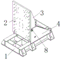
Fig. 1 is a perspective view of the turning machine of the present invention.
Fig. 2 is a schematic diagram of a motion state of the turnover machine turning 90 degrees counterclockwise from the horizontal direction.
Fig. 3 is a bottom view structural diagram of the turnover machine of the present invention.
Detailed Description
In order to facilitate understanding of the present invention, the present invention will be described more fully hereinafter with reference to the accompanying drawings. The preferred embodiments of the present invention are shown in the drawings. The invention may, however, be embodied in many different forms and should not be construed as limited to the embodiments set forth herein. Rather, these embodiments are provided so that this disclosure will be thorough and complete.
Unless defined otherwise, all technical and scientific terms used herein have the same meaning as commonly understood by one of ordinary skill in the art to which this invention belongs.
In this embodiment, as shown in fig. 1 to 3, the utility model discloses a turnover machine, which comprises a frame 1, the higher authority of frame 1 is provided with workstation 2, be provided with upset support 3 below the 2 bottom surfaces of workstation, the higher authority on both sides limit is vertical fixed plate 4 respectively around the frame 1, one side of workstation 2 is provided with locking support 5, install hydraulic pressure station 6 in the right part of frame 1, the vertical spacing branch 7 that is provided with in the higher authority of frame 1 right-hand member, two outsides are connected with jackshaft 8 with every fixed plate 4 respectively around the upset support 3, two inboards are provided with upset hydro-cylinder 9 respectively around the upset support 3, the right-hand member of every fixed plate 4 is provided with upset supporting seat 10, the one end and the upset support 3 of every upset hydro-cylinder 9 are connected, the other end of every upset hydro-cylinder 9 is connected with the upset.
In one embodiment, a locking cylinder 11 is arranged on the middle of the frame 1, and a square bolt 12 is installed at one end of the locking cylinder 11.
In one embodiment, a sensor or a detection switch (not shown) is disposed on one side of the square plug 12.
In one embodiment, the overturning bracket 3 can be driven by the overturning oil cylinder 9 through the intermediate shaft 8 to overturn upwards by a certain angle or overturn downwards by a certain angle, and the workbench 2 can be driven by the overturning bracket 3 to overturn upwards by a certain angle or overturn downwards by a certain angle.
In one embodiment, the certain angle is set to 90 degrees.
In one embodiment, the operation principle of the turnover machine is as follows: firstly, a workpiece to be overturned is placed on a horizontally placed workbench 2, then the workpiece is fixed on the workbench 2 by using a clamp, an overturning support 3 is arranged below the bottom surface of the workbench 2, fixing plates 4 are respectively vertically arranged on the front side edge and the rear side edge of a frame 1, each fixing plate 4 is connected with the overturning support 3 through an intermediate shaft 8, and an overturning support seat 10 arranged at the right end of each fixing plate 4 is connected with an overturning oil cylinder 9 at the end part of the overturning support 3; when the turnover oil cylinder 9 is started and moves rightwards, the turnover bracket 3 with the end connected with the turnover oil cylinder 9 can do turnover motion upwards (namely rotate anticlockwise) under the driving of the turnover oil cylinder 9, the worktable 2 can turn upwards along with the turning of the turning bracket 3, when the sensor senses that the worktable 2 turns upwards to an angle of 90 degrees, the sensor can automatically send the sensed signal to the controller or the control system, the controller or the control system can control the locking oil cylinder 11 to start and operate after receiving the signal, the locking oil cylinder 11 can drive the square bolt 12 connected with the locking oil cylinder to be inserted into the locking support 5 when being started, so that the workbench 2 which is turned over upwards by 90 degrees can be positioned, the phenomenon that the workbench 2 is turned over or turned over is avoided, thereby ensuring the use safety of the device, and at the moment, the workpiece is in a vertical state after being turned over by 90 degrees along with the workbench 2; when the control system sends a lock releasing command to the locking oil cylinder 11, the locking oil cylinder 11 can drive the square mortise lock 12 to withdraw from the locking support 5, then the turning oil cylinder 9 is started and moves leftwards, so that the turning support 3 with the end part connected with the turning oil cylinder 9 can turn 90 degrees downwards (namely turn 90 degrees clockwise) under the driving of the turning oil cylinder 9, the workbench 2 automatically turns downwards along with the turning of the turning support 3, so that the workpiece can return to a horizontally placed state along with the turning of the workbench 2, when the workbench 2 is reset downwards and turned to be close to a horizontal plane, the design of the limiting support rod 7 can limit the downward turning angle of the workbench 2 so as to prevent the workbench 2 from turning over excessively, meanwhile, the limiting support rod 7 can also play a role of supporting the bottom surface of the workbench 2 so as to improve the structural stability of the workbench 2, so that the workpiece placed on the workbench 2 can easily realize 90-degree turning, the turnover device is simple in overall structure, scientific and reasonable in layout, free of manual operation in the turnover process, capable of greatly reducing labor intensity of workers and labor cost of enterprises, convenient and rapid to use and high in practicability.
The utility model discloses a turnover machine, including frame, workstation, upset support, fixed plate, locking support, hydraulic pressure station, spacing branch, jackshaft, upset supporting seat, upset hydro-cylinder, square bolt, locking hydro-cylinder and detection switch. The workbench of the utility model can be driven by the turnover oil cylinder to turn 90 degrees clockwise and 90 degrees anticlockwise, so that a workpiece placed on the workbench can easily and quickly complete 90-degree turnover along with the turnover of the workbench; when the workbench is turned over by 90 degrees upwards, the locking oil cylinder can push the square bolt to be inserted into the locking support arranged on one side of the workbench so as to position the workbench which is turned over by 90 degrees upwards, the use safety factor is high, and the problem of safety accidents caused by the fact that the workbench is turned over is effectively solved; and spacing branch can carry on spacingly to the workstation of upset down, so that when it overturns excessively, it can also play the effect of support to the bottom surface of work piece platform, its upset process need not artifical participation operation, it has realized that can reduce workman's intensity of labour and has reduced the labour cost of enterprise, it is more convenient to use, it has solved the tradition and has adopted the crane to carry out the operating method who overturns to the large-scale rotating device of area shell and lead to its needs the manual work to look for the balance point, artifical counterpoint and the process of overturning because of taking place the bruise easily and cause the problem of damage.
The above-mentioned embodiments are merely examples of the present invention, and are not intended to limit the scope of the invention, which is defined by the claims and the equivalents of the principles and basic structures of the invention.
Claims (5)
1. The utility model provides a upset machine which characterized in that: the hydraulic lifting device comprises a frame, the higher authority of frame is provided with the workstation, be provided with the upset support below the workstation bottom surface, the higher authority on both sides limit is vertical fixed plate that is provided with respectively around the frame, one side of workstation is provided with the locking support, install the hydraulic pressure station in the right part of frame, the higher authority of frame right-hand member is vertical to be provided with spacing branch, both sides are connected with the jackshaft with every fixed plate respectively around the upset support, the right-hand member of every fixed plate is provided with the upset supporting seat, every upset supporting seat is connected with the upset hydro-cylinder with the.
2. A tilter machine as claimed in claim 1, wherein: a locking oil cylinder is arranged on the middle portion of the rack, and a square bolt is installed at one end of the locking oil cylinder.
3. A tilter machine as claimed in claim 2, wherein: and a sensor or a detection switch is arranged on one side of the square bolt.
4. A tilter machine as claimed in claim 1, wherein: the turnover support can be driven by the turnover oil cylinder through the middle shaft to turn upwards by a certain angle or turn downwards by a certain angle, and the workbench can be driven by the turnover support to turn upwards by a certain angle or turn downwards by a certain angle.
5. A tilter as defined in claim 4, wherein: the certain angle is set to 90 degrees.
Priority Applications (1)
| Application Number | Priority Date | Filing Date | Title |
|---|---|---|---|
| CN201920207989.1U CN209939776U (en) | 2019-02-19 | 2019-02-19 | Turnover machine |
Applications Claiming Priority (1)
| Application Number | Priority Date | Filing Date | Title |
|---|---|---|---|
| CN201920207989.1U CN209939776U (en) | 2019-02-19 | 2019-02-19 | Turnover machine |
Publications (1)
| Publication Number | Publication Date |
|---|---|
| CN209939776U true CN209939776U (en) | 2020-01-14 |
Family
ID=69122353
Family Applications (1)
| Application Number | Title | Priority Date | Filing Date |
|---|---|---|---|
| CN201920207989.1U Active CN209939776U (en) | 2019-02-19 | 2019-02-19 | Turnover machine |
Country Status (1)
| Country | Link |
|---|---|
| CN (1) | CN209939776U (en) |
Cited By (3)
| Publication number | Priority date | Publication date | Assignee | Title |
|---|---|---|---|---|
| CN111703361A (en) * | 2020-07-03 | 2020-09-25 | 中国电子科技集团公司第十四研究所 | Manual mechanical limiting device |
| CN112520308A (en) * | 2020-12-22 | 2021-03-19 | 天水锻压机床(集团)有限公司 | Online steel plate overturning roller way scratch preventing system |
| CN118618849A (en) * | 2024-08-12 | 2024-09-10 | 江苏东方成套设备制造集团有限公司 | Plate turnover machine motion mechanism |
-
2019
- 2019-02-19 CN CN201920207989.1U patent/CN209939776U/en active Active
Cited By (3)
| Publication number | Priority date | Publication date | Assignee | Title |
|---|---|---|---|---|
| CN111703361A (en) * | 2020-07-03 | 2020-09-25 | 中国电子科技集团公司第十四研究所 | Manual mechanical limiting device |
| CN112520308A (en) * | 2020-12-22 | 2021-03-19 | 天水锻压机床(集团)有限公司 | Online steel plate overturning roller way scratch preventing system |
| CN118618849A (en) * | 2024-08-12 | 2024-09-10 | 江苏东方成套设备制造集团有限公司 | Plate turnover machine motion mechanism |
Similar Documents
| Publication | Publication Date | Title |
|---|---|---|
| CN209939776U (en) | Turnover machine | |
| CN201102238Y (en) | Turnover machine | |
| CN108438830B (en) | Steel plate blank turnover device | |
| CN110053004A (en) | Automatic turning device is used in shell workpiece processing | |
| CN202702209U (en) | Reversible operation platform | |
| CN206415784U (en) | A kind of flexible stock shelf of vehicle body | |
| CN206084253U (en) | Motor tricycle sheet metal component nut welding position device | |
| CN109119561B (en) | Battery rack with lifting function and lifting method thereof | |
| CN208182566U (en) | Electric power overhaul Working gantry | |
| CN212748287U (en) | Fork truck portal analogue test detection device | |
| CN212425151U (en) | Hook mechanism for electric power operation vehicle | |
| CN210313385U (en) | Lifting device for lifting fork | |
| CN111255275B (en) | Transformer field overhaul frame combined house | |
| CN211110825U (en) | Automatic feeding machine for pipeline installation | |
| CN112573344B (en) | Use method of hoisting and turning-over device for super-large concrete prefabricated stand plate | |
| CN210437218U (en) | Moving platform for placing roller supporting bar for overhauling spinning machine | |
| CN207104133U (en) | Automatic turning repair welding platform for chamber door after picking-up vehicle | |
| CN205145978U (en) | Denitration catalyst module turning device | |
| CN110683457A (en) | Lifting appliance, lifting device and method for quickly overturning pipe piece | |
| CN213583475U (en) | Transformer core assembly assembling vehicle | |
| CN219507449U (en) | Lifting appliance | |
| CN213978645U (en) | Clamping device of prefabricated concrete component of assembly type building | |
| CN217051297U (en) | Hoisting equipment of prefabricated part of fabricated building | |
| CN220578706U (en) | Fixing device suitable for perpendicular handling of gas cylinder | |
| CN219336521U (en) | Middle box body station combination device of dust removal unit |
Legal Events
| Date | Code | Title | Description |
|---|---|---|---|
| GR01 | Patent grant | ||
| GR01 | Patent grant | ||
| PE01 | Entry into force of the registration of the contract for pledge of patent right |
Denomination of utility model: A type of flipper Effective date of registration: 20230629 Granted publication date: 20200114 Pledgee: Ping An Bank Co.,Ltd. Dongguan Branch Pledgor: DONGGUAN NICE MACHINE MANUFACTURING Co.,Ltd. Registration number: Y2023980046754 |
|
| PE01 | Entry into force of the registration of the contract for pledge of patent right |