CN209918648U - Automatic round steel cutting device for machining transmission shaft - Google Patents
Automatic round steel cutting device for machining transmission shaft Download PDFInfo
- Publication number
- CN209918648U CN209918648U CN201920364745.4U CN201920364745U CN209918648U CN 209918648 U CN209918648 U CN 209918648U CN 201920364745 U CN201920364745 U CN 201920364745U CN 209918648 U CN209918648 U CN 209918648U
- Authority
- CN
- China
- Prior art keywords
- driving cylinder
- round steel
- clamping block
- base frame
- cutting
- Prior art date
- Legal status (The legal status is an assumption and is not a legal conclusion. Google has not performed a legal analysis and makes no representation as to the accuracy of the status listed.)
- Active
Links
Images


Abstract
The utility model relates to an automatic round steel cutting device for processing a transmission shaft, which comprises a base; the feeding mechanism is arranged above the base and comprises a U-shaped supporting seat with an upward opening, and rollers rotating in the supporting seat are arranged on the supporting seat; the clamping mechanism comprises a driving cylinder A horizontally arranged above the roller, and a first base frame and a second base frame which are respectively arranged on two sides of the driving cylinder A, and a distance sensor is arranged on the driving cylinder A; the second pedestal is provided with a fixed component and a movable component which are arranged in tandem; and the cutting mechanism comprises a cutting rack and a cutter arranged in the cutting rack, a first push block and a second push block are arranged in the cutting rack close to the discharge chute in a tandem and corresponding manner, and the first push block and the second push block are respectively arranged by driving the driving cylinder C and the driving cylinder D in a front-back driving manner. The utility model has the advantages of simple structure, can realize the cutting requirement of unnecessary length, improve production efficiency.
Description
The technical field is as follows:
the utility model belongs to transmission shaft processing field, concretely relates to round steel automatic cutout device for processing transmission shaft.
Background art:
the workshop of processing transmission shaft needs carry out equidistant cutting off to raw and other materials round steel, and the cutting off of traditional round steel needs the manual work to carry out the material loading, and the cutter from top to bottom realizes cutting off the round steel, can't realize the equidistant cutting of regulation, and when the requirement of cutting off to different length, need operating personnel constantly to measure, consuming time and wasting power can't guarantee production efficiency.
The invention content is as follows:
the utility model aims at overcoming the above not enough, provide a simple structure, can realize cutting off requirement, improvement production efficiency's a round steel automatic cutout device for processing transmission shaft of length not used.
The purpose of the utility model is realized through the following technical scheme: a round steel automatic cutout device for processing transmission shaft includes
A base;
the feeding mechanism is arranged above the base and comprises a U-shaped supporting seat with an upward opening, rollers rotating in the supporting seat are arranged on the supporting seat, meanwhile, round steel is horizontally arranged above the rollers, and the extending direction of the round steel is perpendicular to the extending direction of the rollers;
the clamping mechanism is arranged above the base and comprises a driving cylinder A, a first base frame and a second base frame, the driving cylinder A is horizontally arranged above the roller, the first base frame and the second base frame are respectively arranged on two sides of the driving cylinder A, and a distance sensor is arranged on the driving cylinder A; an adjusting screw which is consistent with the extending direction of the driving cylinder A is arranged on the first base frame, the adjusting screw penetrates through the first base frame, and one end of the adjusting screw, which is close to the roller, is in contact with the driving cylinder A; the second base frame is provided with a fixed component and a movable component which are arranged in tandem, the fixed component comprises a fixed plate fixedly connected with the second base frame, a first lug plate and a first clamping block which are arranged on the inner side of the fixed plate, the first lug plate is arranged above the first clamping block, the movable component comprises a movable plate, a second lug plate and a second clamping block which are arranged on the inner side of the movable plate, the second lug plate is arranged above the second clamping block, the upper end of the movable plate is connected with a driving cylinder B, the driving cylinder B is connected with the upper part of the second base frame and drives the upper end of the second base frame to move back and forth, the first lug plate is arranged corresponding to the second lug plate and is movably connected with a rotating shaft horizontally penetrating through the first lug plate and the second lug plate, the first clamping block is arranged corresponding to the second clamping block, meanwhile, the round steel horizontally extends into the space between the first clamping block and the second clamping block, the inner side wall of the first clamping block, which is close to the round steel, is provided with, the end surface of the inner side of the second clamping block close to the round steel is a concave-convex surface with a wavy structure;
the cutting mechanism is arranged above the base and arranged side by side with the clamping mechanism, the cutting mechanism comprises a cutting rack and a cutter arranged in the cutting rack, a discharge chute arranged downwards is formed in the outer side of the cutting rack, a first push block and a second push block are arranged in the cutting rack and close to the discharge chute in a tandem and corresponding mode, the first push block and the second push block are respectively arranged by a driving cylinder C and a driving cylinder D in a front-back driving mode, the driving cylinder C and the driving cylinder D are connected with the cutting rack, a second notch clamped with round steel is formed in the end face of the inner side of the first push block, and the first notch and the second notch are horizontally arranged in a corresponding mode.
The utility model discloses a further improvement lies in: the supporting seat is connected with the base through bolts, a left roller and a right roller are arranged on the supporting seat, shafts are arranged at two side ends of the rollers and longitudinally penetrate through the supporting seat, a bayonet lock is arranged on any shaft of the roller, and the bayonet lock is arranged on the outer side of the supporting seat.
The utility model discloses a further improvement lies in: one end of the adjusting screw horizontally penetrates through the first base frame, and a screwing nut is sleeved at the position, on the outer end face of the first base frame, of the outer portion of the adjusting screw.
Compared with the prior art, the utility model has the following advantage:
1. the utility model discloses simple structure, can realize cutting off requirement, labour saving and time saving, improvement production efficiency of unnecessary length. Round steel is horizontally placed on the roller and penetrates through the first clamping block and the second clamping block, the round steel is clamped by the first clamping block and the second clamping block along with the driving of the driving cylinder B, the round steel is conveyed to the first push block and the second push block of the cutting mechanism along with the driving of the driving cylinder A, the round steel is clamped by the driving cylinder C and the driving cylinder D and pushed to the cutter, the cutting of the round steel is realized, the manual feeding and discharging are not needed, and the time and the labor are saved; be equipped with distance sensor on the actuating cylinder A, can set up the length of cutting transmission axis body, the motion stroke of actuating cylinder A receives distance sensor influence, guarantees to cut many times and realizes the equidistance.
2. The movable plate is connected with the fixed plate through a rotating shaft, and the movable plate uses the rotating shaft as a hinge point to realize inclined movement along with the pushing of the driving cylinder B to the upper end of the movable plate, so that the second clamping block at the lower end of the movable plate is close to and separated from the first clamping block.
3. The end face of the inner side, close to the round steel, of the second clamping block is a concave-convex face of a wavy structure, so that the contact friction force of the round steel and the second clamping block is improved, the phenomenon of slipping in the clamping process is prevented, a first notch is formed in the end face of the inner side of the first clamping block, and the clamping degree of the round steel, the first clamping block and the second clamping block is further improved.
4. The adjusting screw plays the effect that restriction actuating cylinder A removed, prevents that the effect of enlarging the stroke from appearing because inertia when actuating cylinder A stretches out and draws back right, can't guarantee the equidistance of cutting at every turn, and the position cover that first bed frame outside terminal surface was arranged in to the outside of adjusting screw is equipped with the nut of screwing up, when the transmission shaft of the different length of cutting, can adjust the length of adjusting screw and actuating cylinder A to fix through screwing up the nut, convenient to use is nimble.
Description of the drawings:
fig. 1 is the structure schematic diagram of the utility model relates to a round steel automatic cutout device for processing transmission shaft.
Fig. 2 is a schematic view of a-a of the automatic round steel cutting device for processing the transmission shaft of the present invention.
Fig. 3 is a schematic view of the B-B of the automatic round steel cutting device for processing the transmission shaft of the present invention.
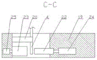
Fig. 4 is a C-C schematic view of the automatic round steel cutting device for processing the transmission shaft of the present invention.
Fig. 5 is the utility model relates to a structural schematic diagram of a supporting seat and gyro wheel for processing round steel automatic cutout device of transmission shaft.
Fig. 6 is a schematic structural view of a second clamping block of the automatic round steel cutting device for processing the transmission shaft of the present invention.
Reference numbers in the figures: 1-base, 2-supporting base, 3-roller, 4-round steel, 5-driving cylinder A, 6-first base frame, 7-second base frame, 8-adjusting screw, 9-fixing plate, 10-first lug plate, 11-first clamping block, 12-second lug plate, 13-second clamping block, 14-movable plate, 15-driving cylinder B, 16-rotating shaft, 17-first notch, 18-concave-convex surface, 19-cutting machine frame, 20-cutter, 21-discharge chute, 22-first push block, 23-second push block, 24-driving cylinder C, 25-driving cylinder D, 26-second notch, 27-shaft, 28-bayonet lock and 29-screwing nut.
The specific implementation mode is as follows:
in order to deepen the understanding of the present invention, the present invention will be further described in detail with reference to the following embodiments and the attached drawings, and the embodiments are only used for explaining the present invention, and do not constitute the limitation to the protection scope of the present invention.
As shown in fig. 1, the utility model discloses an embodiment of a round steel automatic cutting device for processing transmission shaft, include
A base 1;
the feeding mechanism is arranged above the base 1 and comprises a U-shaped supporting seat 2 with an upward opening, rollers 3 rotating in the supporting seat 2 are arranged on the supporting seat 2, meanwhile, round steel 4 is horizontally arranged above the rollers 3, and the extending direction of the round steel 4 is perpendicular to the extending direction of the rollers 3;
the clamping mechanism is arranged above the base 1, and as shown in fig. 2, the clamping mechanism comprises a driving cylinder A5 horizontally arranged above the roller 3, a first base frame 6 and a second base frame 7 respectively arranged at two sides of the driving cylinder A5, and a distance sensor is arranged on the driving cylinder A5; an adjusting screw 8 which is consistent with the extending direction of the driving cylinder A5 is arranged on the first base frame 6, the adjusting screw 8 penetrates through the first base frame 6, and one end of the adjusting screw 8, which is close to the roller 3, is contacted with the driving cylinder A5; the second pedestal 7 is provided with a fixed component and a movable component which are arranged in tandem, the fixed component comprises a fixed plate 9 fixedly connected with the second pedestal 7, a first ear plate 10 and a first clamping block 11 which are arranged on the inner side of the fixed plate 9, the first ear plate 10 is arranged above the first clamping block 11, the movable component comprises a movable plate 14, a second ear plate 12 and a second clamping block 13 which are arranged on the inner side of the movable plate 14, the second ear plate 12 is arranged above the second clamping block 13, the upper end of the movable plate 14 is connected with a driving cylinder B15, the driving cylinder B15 is connected with the upper part of the second pedestal 7 and a driving cylinder B15 drives the upper end of the second pedestal 7 to move back and forth, the first ear plate 10 and the second ear plate 12 are correspondingly arranged and movably connected through a rotating shaft 16 which horizontally penetrates through the first ear plate 10 and the second ear plate 12, the first clamping block 11 and the second clamping block 13 are correspondingly arranged, and the round steel 4 horizontally extends into between the first clamping block 11 and the second clamping block 13, a first notch 17 clamped with the round steel 4 is formed in the inner side wall, close to the round steel 4, of the first clamping block 11, and as shown in fig. 6, the end face, close to the inner side of the round steel 4, of the second clamping block 13 is a wavy concave-convex surface 18;
a cutting mechanism, the cutting mechanism is arranged above the base 1 and arranged side by side with the clamping mechanism, as shown in fig. 3 and 4, the cutting mechanism comprises a cutting rack 19 and a cutter 20 arranged in the cutting rack 19, a discharge chute 21 arranged obliquely downwards is arranged on the outer side of the cutting rack 19, a first push block 22 and a second push block 23 are arranged in the cutting rack 19 and close to the discharge chute 21 in a tandem and corresponding manner, the first push block 22 and the second push block 23 are respectively arranged by a driving cylinder C24 and a driving cylinder D25 in a front-back driving manner, the driving cylinder C24 and the driving cylinder D25 are connected with the cutting rack 19, a second notch 26 clamped with the round steel 4 is arranged on the end face of the inner side of the first push block 22, and the first notch 17 and the second notch 26 are arranged in a horizontal and corresponding manner.
As shown in fig. 5, the supporting base 2 is connected to the base 1 through a bolt, a left roller and a right roller 3 are disposed on the supporting base 2, shafts 27 are disposed at both side ends of the rollers 3, the shafts 27 longitudinally penetrate through the supporting base 2, a latch 28 is disposed on any shaft 27 of the roller 3, and the latch 28 is disposed at an outer side of the supporting base 2.
One end of the adjusting screw 8 horizontally penetrates through the first base frame 6, and a tightening nut 29 is sleeved at a position where the outer part of the adjusting screw 8 is arranged on the outer end face of the first base frame 6. Adjusting screw 8 plays the effect that restriction actuating cylinder A5 removed, and the effect that enlarges the stroke appears because inertia when preventing that actuating cylinder A5 from stretching out and drawing back right, can't guarantee the equidistance of cutting at every turn, when the transmission shaft of cutting different length, can adjust adjusting screw 8 and actuating cylinder A5's length to fix convenient to use is nimble through screwing up nut 29.
The working principle is as follows: the round steel 4 is horizontally placed on the roller 3 and penetrates through the first clamping block 11 and the second clamping block 13, the driving cylinder B15 pushes the movable plate 14 forwards, the first clamping block 11 and the second clamping block 13 tighten the round steel 4, the driving cylinder A5 conveys the round steel 4 to the cutting mechanism at the moment, the round steel 4 is placed in the cutting mechanism, the driving cylinder B15 resets, the first clamping block 11 is separated from the second clamping block 13, the tightening of the round steel 4 is released, the driving cylinder D25 pushes the second pushing block 23 to approach the round steel 4 at the moment, the driving cylinder C24 pushes the first pushing block 22 to approach the second pushing block 23, the round steel 4 is tightened, meanwhile, the driving cylinder C24 continues to push the round steel 4 to move to the second pushing block 23, the round steel 4 is cut off by the cutter 20, the driving cylinder C24 and the driving cylinder D25 reset, the cut-off transmission shaft falls into the discharge chute 21, and the driving cylinder A5 continuously resets according to the steps.
The utility model has simple structure, can realize the cutting-off requirement without length, saves time and labor, improves the production efficiency, does not need manual feeding and discharging, saves time and labor; be equipped with distance sensor on the actuating cylinder A5, can set up the length of cutting transmission axis body, the motion stroke of actuating cylinder A5 is influenced by distance sensor, guarantees that many times cut and realizes the equidistance. The movable plate 14 is connected with the fixed plate 9 through a rotating shaft 16, and as the driving cylinder B15 pushes the upper end of the movable plate 14, the movable plate 14 realizes an inclined movement with the rotating shaft 16 as a hinge point, and the second clamping block 13 at the lower end of the movable plate 14 approaches to and separates from the first clamping block 11. The end face of the inner side of the second clamping block 13 close to the round steel 4 is a concave-convex face 18 of a wavy structure, so that the contact friction force between the round steel 4 and the second clamping block 13 is improved, the phenomenon of slipping in the clamping process is prevented, the end face of the inner side of the first clamping block 11 is provided with a first notch 17, and the clamping degree between the round steel 4 and the first clamping block 11 and the second clamping block 13 is further improved.
It will be understood by those skilled in the art that the present invention is not limited to the above embodiments, and that the foregoing embodiments and descriptions are provided only to illustrate the principles of the present invention without departing from the spirit and scope of the present invention. The scope of the invention is defined by the appended claims and equivalents thereof.
Claims (3)
1. The utility model provides a round steel automatic cutout device for processing transmission shaft which characterized in that: comprises that
A base; the feeding mechanism is arranged above the base and comprises a U-shaped supporting seat with an upward opening, rollers rotating in the supporting seat are arranged on the supporting seat, round steel is horizontally arranged above the rollers, and the extending direction of the round steel is perpendicular to the extending direction of the rollers;
the clamping mechanism is arranged above the base and comprises a driving cylinder A, a first base frame and a second base frame, wherein the driving cylinder A is horizontally arranged above the roller, the first base frame and the second base frame are respectively arranged on two sides of the driving cylinder A, and a distance sensor is arranged on the driving cylinder A; an adjusting screw which is consistent with the extending direction of the driving cylinder A is arranged on the first base frame, the adjusting screw penetrates through the first base frame, and one end, close to the roller, of the adjusting screw is in contact with the driving cylinder A; the second base frame is provided with a fixed component and a movable component which are arranged in tandem, the fixed component comprises a fixed plate fixedly connected with the second base frame, a first lug plate and a first clamping block which are arranged on the inner side of the fixed plate, the first lug plate is arranged above the first clamping block, the movable component comprises a movable plate, a second lug plate and a second clamping block which are arranged on the inner side of the movable plate, the second lug plate is arranged above the second clamping block, the upper end of the movable plate is connected with a driving cylinder B, the driving cylinder B is connected with the upper part of the second base frame and drives the upper end of the second base frame to move back and forth, the first lug plate and the second lug plate are correspondingly arranged and movably connected through a rotating shaft which horizontally penetrates through the first lug plate and the second lug plate, the first clamping block and the second clamping block are correspondingly arranged, and round steel horizontally extends between the first clamping block and the second clamping block, the inner side wall of the first clamping block, which is close to the round steel, is provided with a first notch clamped with the round steel, and the end surface of the inner side of the second clamping block, which is close to the round steel, is a corrugated concave-convex surface;
a cutting mechanism, cutting mechanism arranges the base top in and sets up side by side with fixture, cutting mechanism is including cutting off the frame and arranging the cutter in cutting off the frame in, the outside of cutting off the frame is equipped with the blown down tank that the downward sloping set up, it is equipped with first ejector pad, second ejector pad to correspond after one to set up to cut off the position that is close to the blown down tank in the frame, first ejector pad and second ejector pad are respectively by driving cylinder C, driving cylinder D front and back drive setting, driving cylinder C, driving cylinder D and cut off the frame and be connected, the medial surface of first ejector pad is equipped with the second notch with the round steel block, first notch corresponds the setting with second notch level.
2. The automatic round steel cutting device for machining the transmission shaft as claimed in claim 1, wherein: the supporting seat is connected with the base through bolts, a left roller and a right roller are arranged on the supporting seat, shafts are arranged at two side ends of the rollers and longitudinally penetrate through the supporting seat, a bayonet lock is arranged on any shaft of the rollers, and the bayonet lock is arranged on the outer side of the supporting seat.
3. The automatic round steel cutting device for machining the transmission shaft as claimed in claim 1, wherein: one end of the adjusting screw horizontally penetrates through the first base frame, and a screwing nut is sleeved at the position, on the outer end face of the first base frame, where the outer part of the adjusting screw is arranged.
Priority Applications (1)
| Application Number | Priority Date | Filing Date | Title |
|---|---|---|---|
| CN201920364745.4U CN209918648U (en) | 2019-03-21 | 2019-03-21 | Automatic round steel cutting device for machining transmission shaft |
Applications Claiming Priority (1)
| Application Number | Priority Date | Filing Date | Title |
|---|---|---|---|
| CN201920364745.4U CN209918648U (en) | 2019-03-21 | 2019-03-21 | Automatic round steel cutting device for machining transmission shaft |
Publications (1)
| Publication Number | Publication Date |
|---|---|
| CN209918648U true CN209918648U (en) | 2020-01-10 |
Family
ID=69070351
Family Applications (1)
| Application Number | Title | Priority Date | Filing Date |
|---|---|---|---|
| CN201920364745.4U Active CN209918648U (en) | 2019-03-21 | 2019-03-21 | Automatic round steel cutting device for machining transmission shaft |
Country Status (1)
| Country | Link |
|---|---|
| CN (1) | CN209918648U (en) |
-
2019
- 2019-03-21 CN CN201920364745.4U patent/CN209918648U/en active Active
Similar Documents
| Publication | Publication Date | Title |
|---|---|---|
| CN207757337U (en) | A kind of cuts in metallic pipe device with clearing function | |
| CN109551540B (en) | Progressive coconut cutting and conveying device and using method thereof | |
| CN209918648U (en) | Automatic round steel cutting device for machining transmission shaft | |
| CN106985245B (en) | A kind of truncation of high-performance timber utilizes equipment | |
| CN211333530U (en) | Punching device for automotive upholstery | |
| CN2131629Y (en) | Improved punch press automatic material advancing machine | |
| CN212242282U (en) | Multifunctional efficient sheet rolling machine | |
| CN102430670A (en) | High-speed cutting machine for wire rod with large outer diameter | |
| CN212121670U (en) | Automatic feeding machine for numerical control lathe | |
| CN208731990U (en) | A kind of bolt auto-sequencing feeding distribution mechanism | |
| CN201832932U (en) | High speed cut-off machine for wire stock with large outer diameter | |
| CN219791612U (en) | Round steel pushing device | |
| CN219924351U (en) | Automatic material loading formula piercing press | |
| CN211842380U (en) | Wood working cutting machine that can adjust | |
| CN216829875U (en) | Automatic sawing machine of feeding | |
| CN214350848U (en) | Aluminum product cutting device | |
| CN2266491Y (en) | Woodworking multi-purpose miller | |
| CN220182344U (en) | Collecting mechanism of plastic film transverse cutting machine | |
| CN219900508U (en) | Water pump impeller processing cutting device | |
| CN213764204U (en) | High-efficient aluminum plate cutting device | |
| CN212286087U (en) | Round steel cutting equipment | |
| CN217648533U (en) | High-safety sliding table saw suitable for processing office furniture | |
| CN216575272U (en) | Stamping die waste material ejection mechanism | |
| CN217775700U (en) | Gantry shear feeding device | |
| CN216298141U (en) | Multifunctional plate cutting machine |
Legal Events
| Date | Code | Title | Description |
|---|---|---|---|
| GR01 | Patent grant | ||
| GR01 | Patent grant |