CN209918541U - Medical waste environmental protection processing apparatus - Google Patents
Medical waste environmental protection processing apparatus Download PDFInfo
- Publication number
- CN209918541U CN209918541U CN201920074850.4U CN201920074850U CN209918541U CN 209918541 U CN209918541 U CN 209918541U CN 201920074850 U CN201920074850 U CN 201920074850U CN 209918541 U CN209918541 U CN 209918541U
- Authority
- CN
- China
- Prior art keywords
- box
- box body
- pair
- wall surface
- same structure
- Prior art date
- Legal status (The legal status is an assumption and is not a legal conclusion. Google has not performed a legal analysis and makes no representation as to the accuracy of the status listed.)
- Expired - Fee Related
Links
Images


Abstract
The utility model discloses a medical waste environment-friendly treatment device, which comprises a box body, a first box cover, a second box cover and a fan; the box is the cavity structure, and inside is divided into two cavitys to set up two pairs of through-holes that the structure is the same on two walls around in the left side cavity, first case lid activity is settled in box left side cavity top, second case lid head motion device is in box right side cavity top, the fan inlays and adorns in second case lid center department, the utility model relates to a rubbish environmental protection processing technology field, through servo motor's transmission, drives two the same crushing rotation and goes on smashing rubbish, and installs the bactericidal lamp in the right side cavity and be used for disinfection, and the suction through the fan is with the gas after inside disinfecting outside the box of filtering and purifying a section of thick bamboo discharge, with waste classification recovery, processing like this, will significantly reduce medical waste to atmosphere, produce harm to the human body.
Description
Technical Field
The utility model relates to a rubbish environmental protection processing technology field specifically is a medical waste environmental protection processing apparatus.
Background
Medical waste refers to waste products generated by medical institutions in medical, preventive, health care and other related activities and having direct or indirect infectious, toxic and other hazardous properties, and specifically includes infectious, pathological, traumatic, medicinal and chemical waste products. For example: used cotton balls, sandcloths, adhesive tapes, waste water, disposable medical instruments, postoperative wastes, overdue medicines and the like belong to medical wastes. The wastes contain a large amount of bacterial viruses and have certain characteristics of space pollution, acute viral infection and latent infection, if the wastes are not managed and are discarded at will, the wastes are mixed with household garbage and are scattered into the living environment of people, the wastes pollute the atmosphere, water sources, land, animals and plants, cause disease transmission and seriously harm the physical and mental health of people.
Disclosure of Invention
The utility model provides a not enough to prior art, the utility model provides a medical waste environmental protection processing apparatus, solved the cotton ball that has used in the medical treatment, the gauze, the adhesive tape, waste water, disposable medical instrument, the discarded object of postoperative, the space pollution that rubbish wastes such as overdue medicine produced, these wastes material contain a large amount of bacterial virus, and have certain space pollution, acute viral infection and latent infectious characteristics, if do not strengthen the management, abandon at will, let it sneak into domestic waste, in the flow disperses people's living environment, will pollute the atmosphere, the water source, land and animal and plant, cause the disease to spread, seriously endanger people's physical and mental health, produce the serious consequence of endangering life even to the people who contacts for a long time.
In order to realize the above purpose, the utility model discloses a following technical scheme realizes a medical waste environmental protection processing apparatus, include: the device comprises a box body, a first box cover, a second box cover, a fan, a filtering and purifying cylinder, a pair of sterilizing lamps with the same structure, a crushing and collecting box, a common collecting box and two pairs of pulleys with the same structure; the box body is of a cavity structure, the interior of the box body is divided into two cavities, two pairs of through holes with the same structure are formed in the front wall surface and the rear wall surface in the left cavity, the first box cover is movably arranged above the left cavity of the box body, the second box cover is movably arranged above the right cavity of the box body, the fan is embedded in the center of the second box cover, the filtering and purifying cylinder is fixedly arranged on the lower wall surface of the second box cover and is connected with the lower wall surface of the fan, the sterilizing lamps are respectively fixed on the left side wall surface and the right side wall surface in the right cavity of the box body, the crushing and collecting box is arranged on the lower wall surface in the left cavity of the box body, the common collecting box is arranged on the lower wall surface in the right cavity;
the crushing structure mainly comprises: the grinding device comprises two pairs of bearings with the same structure, a pair of shaft bodies with the same structure, a pair of grinding rollers with the same structure, a pair of gears with the same structure, a mounting box, a fixed block and a servo motor;
the grinding roller grinding device comprises a box body, a grinding roller, a servo motor, a pair of bearings, a pair of gears, an installation box, a fixing block, a pair of grinding rollers, a pair of gears, a pair of grinding rollers, a pair of gears and a pair of grinding rollers, wherein the two pairs of bearings are embedded into through holes in the front wall and the rear wall of a cavity in the left side of the box body respectively, two ends of the shaft body are inserted into the two pairs of bearings respectively, a first helical gear is installed at the right end of one shaft body, the pair of grinding rollers are sleeved on the pair of shaft bodies respectively.
Preferably, the handles with the same structure are mounted on the upper wall surfaces of the first box cover and the second box cover: the handle is used for exerting force.
Preferably, a pair of buttons are mounted on the right side wall surface of the box body: the button is used for on-off control.
Preferably, swing joint's the door of collecting is all installed with the right side wall to the box left side wall: the collecting door is used for carrying collected garbage.
Preferably, two pairs of baffles with the same structure are installed on the left side wall and the right side wall in the cavity on the left side of the box body: the baffle is used for limiting the position of the garbage.
Preferably, a gasket is installed between the pair of grinding rolls and the inner wall surface of the box body: the gasket is used to prevent rubbing against the inner wall.
Advantageous effects
To the problem, the utility model provides a medical waste environmental protection processing apparatus. The method has the following beneficial effects: this medical waste environmental protection processing apparatus, the present case dress new point lies in, divide into two cavitys with inside through whole box, and the left side cavity is used for retrieving the medical waste that can smash, for example: a glass bottle for a drug, a needle tube for a drug, and the like; the right cavity is used for the recovery of common, non-fragmentable medical waste, such as: dropper, cotton swab, medical cotton, etc.; and through servo motor's transmission, drive two the same crushing rolls and rotate and carry out to rubbish smashing, the rubbish after smashing is collected to the crushing collecting box through the below, and the bactericidal lamp in the cavity of right side, can be used to disinfection and sterilization to through the suction of fan, the gas after will inside disinfecting is through filtering and purifying a section of thick bamboo discharge outside the box, and the amazing smell is asked when placing medical personnel and opening the case lid, with waste classification recovery, processing like this, will significantly reduce medical waste to atmosphere, produce harm to the human body.
Drawings
Fig. 1 is a schematic view of the structure of the medical waste environment-friendly treatment device of the present invention.
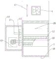
Fig. 2 is a left side view sectional structure schematic diagram of the medical waste environment-friendly treatment device.
Fig. 3 is a schematic view of a top view structure of the medical waste environment-friendly treatment device of the present invention.
In the figure: 1-a box body; 2-a first cover; 3-a second box cover; 4-a fan; 5-a filtering and purifying cylinder; 6-a germicidal lamp; 7-crushing and collecting box; 8-a common collection box; 9-a pulley; 10-a bearing; 11-shaft 12-grinding roll; 13-a gear; 14-mounting a box; 15-fixing block; 16-a servo motor; 17 a handle; 18-a button; 19-a harvesting gate; 20-a baffle plate; 21-shim.
Detailed Description
The technical solutions in the embodiments of the present invention will be described clearly and completely with reference to the accompanying drawings in the embodiments of the present invention, and it is obvious that the described embodiments are only some embodiments of the present invention, not all embodiments. Based on the embodiments in the present invention, all other embodiments obtained by a person skilled in the art without creative work belong to the protection scope of the present invention.
The following are the types of some of the electrical components mentioned in this document;
a servo motor: the model is 220V/RJ 090-E03520.
A germicidal lamp: model LY-90W UV lamp.
A fan; the model is YDHA-16.
The following is a description of the shapes and materials of some parts in the present case;
a box body: is a rectangular stainless steel cavity structure.
The fixed block is in a rectangular steel structure.
Grinding and rolling: is an alloy steel structure.
A filtering and purifying cylinder: is an active carbon air filtration and purification net core cylinder.
All the electrical components in the present application are connected with the power supply adapted to the electrical components through a wire, and an appropriate controller and an appropriate encoder should be selected according to actual conditions to meet control requirements, and specific connection and control sequences should be obtained.
Example (b): the scheme is a medical waste environment-friendly treatment device, as can be seen from fig. 1-3, and mainly comprises: the device comprises a box body 1, a first box cover 2, a second box cover 3, a fan 4, a filtering and purifying cylinder 5, a pair of sterilizing lamps 6 with the same structure, a crushing and collecting box 7, a common collecting box 8 and two pairs of pulleys 9 with the same structure, wherein the connection relation is as follows;
the box body 1 is of a cavity structure, the interior of the box body is divided into two cavities, two pairs of through holes with the same structure are formed in the front wall surface and the rear wall surface in the left cavity, the first box cover 2 is movably arranged above the left cavity of the box body 1, the second box cover 3 is movably arranged above the right cavity of the box body 1, the fan 4 is embedded in the center of the second box cover 3, the filtering and purifying cylinder 5 is fixedly arranged on the lower wall surface of the second box cover 3 and is connected with the lower wall surface of the fan 4, the pair of sterilizing lamps 6 are respectively fixed on the left side wall surface and the right side wall surface in the right cavity of the box body 1, the crushing and collecting box 7 is arranged on the lower wall surface in the left cavity of the box body 1, the common collecting box 8 is arranged on the lower;
crushing structure, it mainly includes: two pairs of bearings 10 with the same structure, a pair of shaft bodies 11 with the same structure, a pair of grinding rolls 12 with the same structure, a pair of gears 13 with the same structure, a mounting box 14, a fixed block 15 and a servo motor 16 are connected as follows;
two pairs of bearings 10 are respectively embedded in through holes in the front wall and the rear wall in a cavity on the left side of the box body 1, two ends of a pair of shaft bodies 11 are respectively inserted in the two pairs of bearings 10, a first helical gear is installed at the right end of one shaft body 11, a pair of grinding rollers 12 are respectively sleeved on the pair of shaft bodies 11, a pair of gears 13 are sleeved on the right ends of the pair of shaft bodies 11, an installation box 14 is fixedly installed on the rear wall surface of the box body 1, a fixed block 15 is installed on the lower wall surface in the installation box 14, a servo motor 16 is fixedly installed on the fixed block 15, a second helical gear is installed at the driving end of the servo;
as can be seen from the above, the servo motor 16 in the installation box 14 rotates counterclockwise, one shaft body 11 rotates in the bearing 10 through the engagement of the bevel gears, and the two shaft bodies 11 rotate in opposite directions through the engagement of the gears sleeved on the left ends of the two shaft bodies 11, so as to drive the rolling rollers 12 on the shaft bodies 11 to rotate for crushing.
According to the general knowledge, firstly, after the equipment is powered on, the workers open the first box cover 2 or the second box cover 3 through the handle 17 on the box cover and put different types of garbage into the box body 1; when the garbage is common garbage, the garbage is placed into a cavity on the right side in the box body 1, the sterilizing lamp 6 can be controlled to work through one button 18 for sterilization, and suction force is generated through the rotation of the fan 4, so that gas in the box is discharged through the filtering and purifying of the filtering and purifying cylinder 5; if the garbage is crushed, the garbage is put into a left cavity in a box body 1, after a first box cover 2 is closed, the garbage is dropped into the middle of two crushing rollers 12 through a baffle 20 in the box body 1, the other button 18 can control a servo motor 16 on a fixed block 15 in an installation box 14 to rotate anticlockwise, one shaft body 11 rotates in a bearing 10 through meshing transmission of helical gears, the two shaft bodies 11 are meshed and connected through a gear 13 sleeved on the left ends of the two shaft bodies 11, the two shaft bodies 11 rotate oppositely, the crushing rollers 12 on the shaft body 11 are driven to rotate for crushing, and the crushing rollers 12 are prevented from rubbing the inner wall through the matching of gaskets 21; its all kinds of rubbish will be collected in smashing collecting box 7 and ordinary class collecting box 8, and the staff accessible box 1 is last left side wall and the door 19 of receiving of right side wall carry clearance rubbish, also can remove through pulley 9.
Preferably, the handles 17 of the same structure are mounted on the upper wall surfaces of the first cover 2 and the second cover 3: the handle 17 is used for exerting force.
Preferably, a pair of buttons 18 are further installed on the right side wall surface of the case 1: the button 18 is used for control of the switch.
Preferably, the left side wall and the right side wall of the box body 1 are both provided with a movably connected collecting door 19: the collection door 19 is used to carry collected garbage.
As the preferred scheme, further, two pairs of baffles 20 with the same structure are installed on the left side wall and the right side wall in the cavity on the left side of the box body 1: the baffle 20 serves to restrict the position of the trash.
Preferably, a gasket 21 is installed between the pair of grinding rolls 12 and the inner wall surface of the case 1: the spacer 21 serves to prevent rubbing against the inner wall.
It is noted that, herein, relational terms such as first and second, and the like may be used solely to distinguish one entity or action from another entity or action without necessarily requiring or implying any actual such relationship or order between such entities or actions. Also, the terms "comprises," "comprising," or any other variation thereof, are intended to cover a non-exclusive inclusion, such that a process, method, article, or apparatus that comprises a list of elements does not include only those elements but may include other elements not expressly listed or inherent to such process, method, article, or apparatus. Without further limitation. The use of the phrase "comprising one of the elements does not exclude the presence of other like elements in the process, method, article, or apparatus that comprises the element.
Although embodiments of the present invention have been shown and described, it will be appreciated by those skilled in the art that changes, modifications, substitutions and alterations can be made in these embodiments without departing from the principles and spirit of the invention, the scope of which is defined in the appended claims and their equivalents.
Claims (6)
1. An environment-friendly medical waste disposal device, comprising: the device comprises a box body (1), a first box cover (2), a second box cover (3), a fan (4), a filtering and purifying cylinder (5), a pair of sterilizing lamps (6) with the same structure, a crushing and collecting box (7), a common collecting box (8) and two pairs of pulleys (9) with the same structure; the device is characterized in that the box body (1) is of a cavity structure, the interior of the box body is divided into two cavities, two pairs of through holes with the same structure are arranged on the front wall surface and the rear wall surface in the left cavity, the first box cover (2) is movably arranged above the left cavity of the box body (1), the second box cover (3) is movably arranged above the right cavity of the box body (1), the fan (4) is embedded in the center of the second box cover (3), the filtering and purifying cylinder (5) is fixedly arranged on the lower wall surface of the second box cover (3) and is connected with the lower wall surface of the fan (4), the pair of sterilizing lamps (6) are respectively fixed on the left side wall surface and the right side wall surface in the right cavity of the box body (1), the crushing and collecting box (7) is arranged on the lower wall surface in the left cavity of the box body (1), the common collecting box (8) is arranged on the lower wall surface in the right cavity of the box body (, a crushing structure is also arranged in the box body (1);
the crushing structure mainly comprises: two pairs of bearings (10) with the same structure, a pair of shaft bodies (11) with the same structure, a pair of grinding rolls (12) with the same structure, a pair of gears (13) with the same structure, a mounting box (14), a fixed block (15) and a servo motor (16);
the grinding device is characterized in that two pairs of bearings (10) are embedded in through holes in the front wall and the rear wall in a cavity on the left side of a box body (1) respectively, two ends of a pair of shaft bodies (11) are inserted in the two pairs of bearings (10) respectively, a first helical gear is installed at the right end of one shaft body (11), a pair of grinding rollers (12) are sleeved on the pair of shaft bodies (11) respectively, a pair of gears (13) are sleeved on the right ends of the pair of shaft bodies (11), an installation box (14) is fixedly arranged on the rear wall surface of the box body (1), a fixed block (15) is arranged on the inner lower wall surface of the installation box (14), a servo motor (16) is fixedly arranged on the fixed block (15), a second helical gear is installed at the driving end of the servo motor, and the.
2. The environment-friendly medical waste disposal device according to claim 1, wherein the handles (17) with the same structure are mounted on the upper wall surfaces of the first cover (2) and the second cover (3): the handle (17) is used for exerting force.
3. The environment-friendly medical waste disposal device according to claim 1, wherein a pair of buttons (18) are installed on the right side wall surface of the box body (1): the button (18) is used for on-off control.
4. The environment-friendly medical waste disposal device according to claim 3, wherein the left side wall and the right side wall of the box body (1) are provided with movably connected collecting doors (19): the collecting door (19) is used for conveying collected garbage.
5. The environment-friendly medical waste disposal device according to claim 4, wherein two pairs of baffles (20) with the same structure are installed on the left and right side walls in the left cavity of the box body (1): the baffle (20) is used for limiting the position of the garbage.
6. The environment-friendly medical waste disposal device according to claim 1, wherein a gasket (21) is installed between the pair of grinding rolls (12) and the inner wall surface of the housing (1): the spacer (21) is used to prevent rubbing against the inner wall.
Priority Applications (1)
| Application Number | Priority Date | Filing Date | Title |
|---|---|---|---|
| CN201920074850.4U CN209918541U (en) | 2019-01-17 | 2019-01-17 | Medical waste environmental protection processing apparatus |
Applications Claiming Priority (1)
| Application Number | Priority Date | Filing Date | Title |
|---|---|---|---|
| CN201920074850.4U CN209918541U (en) | 2019-01-17 | 2019-01-17 | Medical waste environmental protection processing apparatus |
Publications (1)
| Publication Number | Publication Date |
|---|---|
| CN209918541U true CN209918541U (en) | 2020-01-10 |
Family
ID=69067271
Family Applications (1)
| Application Number | Title | Priority Date | Filing Date |
|---|---|---|---|
| CN201920074850.4U Expired - Fee Related CN209918541U (en) | 2019-01-17 | 2019-01-17 | Medical waste environmental protection processing apparatus |
Country Status (1)
| Country | Link |
|---|---|
| CN (1) | CN209918541U (en) |
Cited By (2)
| Publication number | Priority date | Publication date | Assignee | Title |
|---|---|---|---|---|
| CN111359711A (en) * | 2020-03-16 | 2020-07-03 | 浙江传超环保科技有限公司 | Garbage crushing equipment with cleaning function |
| CN111992571A (en) * | 2020-09-01 | 2020-11-27 | 杨兆锋 | Medical cotton swab processing apparatus |
-
2019
- 2019-01-17 CN CN201920074850.4U patent/CN209918541U/en not_active Expired - Fee Related
Cited By (3)
| Publication number | Priority date | Publication date | Assignee | Title |
|---|---|---|---|---|
| CN111359711A (en) * | 2020-03-16 | 2020-07-03 | 浙江传超环保科技有限公司 | Garbage crushing equipment with cleaning function |
| CN111359711B (en) * | 2020-03-16 | 2021-10-08 | 邵玉英 | Garbage crushing equipment with cleaning function |
| CN111992571A (en) * | 2020-09-01 | 2020-11-27 | 杨兆锋 | Medical cotton swab processing apparatus |
Similar Documents
| Publication | Publication Date | Title |
|---|---|---|
| CN108405054B (en) | Medical waste innocent treatment device | |
| CN111530547A (en) | Environment-friendly medical waste treatment device | |
| CN113213009B (en) | Operating room abandonment refuse collection processing apparatus | |
| CN209918541U (en) | Medical waste environmental protection processing apparatus | |
| CN208004484U (en) | A kind of multifunctional medical destroying machine | |
| CN107583752A (en) | A kind for the treatment of of!medical waste device easy to remove | |
| CN216801076U (en) | Waste treatment device with disinfection function | |
| CN211026492U (en) | Medical operating room nursing waste treatment device | |
| CN211952774U (en) | Medical waste recovery processing device for infectious department | |
| CN205268678U (en) | Equipment of disinfecting is smashed to medical waste | |
| CN208037270U (en) | A kind of rotary push formula medical waste water separating and treating apparatus | |
| CN214453969U (en) | Medical trash can with auto-induction lid | |
| CN113926543A (en) | Medical waste treatment equipment | |
| CN210750364U (en) | Emergency treatment surgical patient first aid processing apparatus | |
| CN210303960U (en) | Medical waste treatment device | |
| CN208135183U (en) | A kind of hospital's clinical waste storage device | |
| CN214132033U (en) | Medical waste treatment device convenient to move | |
| CN209918017U (en) | Medical waste processing system is with disinfection reducing mechanism | |
| CN2834551Y (en) | Bucket for centralizing and disposing medical waste appliance | |
| CN112193674A (en) | Operating room nursing waste collection device | |
| CN219502248U (en) | Infection-preventing isolation device for clinical rehabilitation | |
| CN213099712U (en) | A sterilization apparatus for taking germ rubbish | |
| CN111687170A (en) | Environment-friendly harmless treatment device for medical waste garbage | |
| CN212940754U (en) | Air sterilizing device | |
| CN212681112U (en) | Waste treatment device for neurology child nursing |
Legal Events
| Date | Code | Title | Description |
|---|---|---|---|
| GR01 | Patent grant | ||
| GR01 | Patent grant | ||
| CF01 | Termination of patent right due to non-payment of annual fee | ||
| CF01 | Termination of patent right due to non-payment of annual fee |
Granted publication date: 20200110 Termination date: 20210117 |