CN203659905U - A solar energy assembly frame dismounting device - Google Patents
A solar energy assembly frame dismounting device Download PDFInfo
- Publication number
- CN203659905U CN203659905U CN201320862149.1U CN201320862149U CN203659905U CN 203659905 U CN203659905 U CN 203659905U CN 201320862149 U CN201320862149 U CN 201320862149U CN 203659905 U CN203659905 U CN 203659905U
- Authority
- CN
- China
- Prior art keywords
- driving lever
- solar components
- frame equipment
- equipment open
- lever
- Prior art date
- Legal status (The legal status is an assumption and is not a legal conclusion. Google has not performed a legal analysis and makes no representation as to the accuracy of the status listed.)
- Expired - Fee Related
Links
Images

Classifications
-
- Y—GENERAL TAGGING OF NEW TECHNOLOGICAL DEVELOPMENTS; GENERAL TAGGING OF CROSS-SECTIONAL TECHNOLOGIES SPANNING OVER SEVERAL SECTIONS OF THE IPC; TECHNICAL SUBJECTS COVERED BY FORMER USPC CROSS-REFERENCE ART COLLECTIONS [XRACs] AND DIGESTS
- Y02—TECHNOLOGIES OR APPLICATIONS FOR MITIGATION OR ADAPTATION AGAINST CLIMATE CHANGE
- Y02P—CLIMATE CHANGE MITIGATION TECHNOLOGIES IN THE PRODUCTION OR PROCESSING OF GOODS
- Y02P70/00—Climate change mitigation technologies in the production process for final industrial or consumer products
- Y02P70/50—Manufacturing or production processes characterised by the final manufactured product
Landscapes
- Photovoltaic Devices (AREA)
Abstract
A solar energy assembly frame dismounting device comprises a machine bench. The upper surface of the machine bench is a working surface. The working surface is provided with two push rods which are distributed in opposite mode and which are in mutual linkage. The push rods are connected with driving structures used for driving the two push rods to approach each other or separate from each other. The driving structures comprise driven rods connecting the corresponding sides of the push rods and driving rods connecting both the driven rods. According to the solar energy assembly frame dismounting device of the utility model, the frame dismounting is easy; the efficiency is high; a metal frame and other fitting which are dismounted will not easily be damaged; the structure is simple; and the manufacturing cost is low.
Description
Technical field
The utility model relates to a kind of solar components and tears frame equipment open, belongs to solar module and manufactures field.
Background technology
Solar module utilizes mode as a kind of new solar energy, is just widely used.The structure of solar module, by solar cell wafer, is arranged at solar cell wafer front and back and forms for the protection of light-passing board and the backboard of wafer.For ease of arranging, most solar modules are rectangle, and for the ease of installing, solar module is provided with metal frame.
In traditional production technology, especially metal form rectangle frame in manufacturing process very easily because formation rhombus not in place is installed, or solar components in the end detects assembly when factory testing and has flaw, above situation all needs the assembly of installation metal frame to take apart and do over again, doing over again is in the past very difficult in the time tearing frame open, and easily the glass light-passing board to assembly front or metal frame itself produce and destroy.
Utility model content
The utility model, for solving prior art problem, provides a kind of esy to use, safe and reliable frame equipment of tearing open.
The technical solution of the utility model is: a kind of solar components is torn frame equipment open, comprise board, the upper surface of described board is working face, on described working face, be provided with two and relatively distribute and the push rods of interlock mutually, described push rod be connected with for drive two described push rods mutually near or the Drive Structure that is separated from each other; Described Drive Structure comprises the follower lever that is connected in described push rod opposite side, and connects the driving lever of all follower levers.
As preferably, described driving lever is connected with external screw thread by the internal thread cooperatively interacting with described follower lever, and described driving lever and described follower lever are coaxial, in the time that described driving lever rotates along central shaft, described follower lever under described internal thread and described externally threaded driving mutually near or mutually away from.
As preferably, on described driving lever, being provided with cross section is not circular limiting section.
As preferably, described limiting section is fixedly installed and is useful on the vertical rotation handle that drives described driving lever to rotate.
As preferably, described follower lever and described push rod are horizontally hinged, and described driving lever and all described follower levers are horizontally hinged.
As preferably, described driving lever is fixedly connected with to be useful on and drives the handle that horizontally rotates that described driving lever horizontally rotates.
As preferably, described in horizontally rotate handle and be fixedly installed the holding rod of horizontal distribution.
As preferably, described push rod comprises the perpendicular outer lining bar of moving direction that is arranged at outermost and described push rod, for connecting the transiting rod of described follower lever and described outer lining bar.
As preferably, on described board, be provided with around the described working face back-up ring of a week.
As preferably, the outer surface of the upper surface of described working face, the inner surface of described back-up ring and described push rod is provided with resilient coating.
In sum, the utility model in use, is inverted in frame assembly to be torn open on working face, by mutually close two push rods, is placed in the metal frame of frame assembly to be torn open, rotates driving lever, and two push rods are separated, by lower metal frame top assembly.Swing handle adopts lever principle, obtains larger moment by the longer arm of force, and firm metal frame is removed smoothly, and resilient coating has guaranteed that tearing open in frame process, assembly can arbitrarily not move, and can not worn and not torn by hard thing in light-passing board surface.
Therefore, the utlity model has following advantage:
1, tear frame open simple, efficiency is high, and the metal frame of pulling down and other accessories are not fragile;
2, simple in structure, low cost of manufacture.
Accompanying drawing explanation
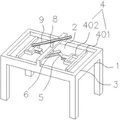
Fig. 1 is the utility model embodiment mono-structural representation;
Fig. 2 is the utility model embodiment bis-structural representations.
In figure, 1, board, 2, working face, 3, back-up ring, 4, push rod, 401, outer lining bar, 402, transiting rod, 5, follower lever, 6, driving lever, 601, limiting section, 7, vertical rotation handle, 8, horizontally rotate handle, 9, holding rod.
Embodiment
With embodiment, the utility model is described in further detail below.
Embodiment mono-:
A kind of solar components is torn frame equipment open, as shown in Figure 1, comprises board 1, and the upper surface of board 1 is working face 2, is provided with around the working face back-up ring of 2 one weeks on board 1.On working face 2, be provided with two and relatively distribute and the push rods 4 of interlock mutually, push rod 4 be connected with for drive two push rods 4 mutually near or the Drive Structure that is separated from each other; Drive Structure comprises the follower lever 5 that is connected in push rod 4 opposite sides, and connects the driving lever 6 of all follower levers 5.Push rod 4 comprises the perpendicular outer lining bar 401 of moving direction that is arranged at outermost and push rod 4, for connecting the transiting rod 402 of follower lever 5 and outer lining bar 401.Driving lever 6 is connected with external screw thread by the internal thread cooperatively interacting with follower lever 5, and driving lever 6 and follower lever 5 are coaxial, in the time that driving lever 6 rotates along central shaft, follower lever 5 under internal thread and externally threaded driving mutually near or mutually away from, on driving lever 6, being provided with cross section is not circular limiting section 601, and limiting section 601 is fixedly installed and is useful on the vertical rotation handle 7 that drives driving lever 6 to rotate.
The outer surface of the upper surface of working face 2, the inner surface of back-up ring 3 and push rod 4 is provided with resilient coating.
When use, frame assembly to be torn open is inverted on working face 2, by mutually close two push rods 4, is placed in the metal frame of frame assembly to be torn open, by rotating driving lever 6, two push rods 4 are separated, by lower metal frame top assembly.
Embodiment bis-:
A kind of solar components is torn frame equipment open, as shown in Figure 2, comprises board 1, and the upper surface of board 1 is working face 2, is provided with around the working face back-up ring of 2 one weeks on board 1.On working face 2, be provided with two and relatively distribute and the push rods 4 of interlock mutually, push rod 4 be connected with for drive two push rods 4 mutually near or the Drive Structure that is separated from each other; Drive Structure comprises the follower lever 5 that is connected in push rod 4 opposite sides, and connects the driving lever 6 of all follower levers 5.Push rod 4 comprises the perpendicular outer lining bar 401 of moving direction that is arranged at outermost and push rod 4, for connecting the transiting rod 402 of follower lever 5 and outer lining bar 401.Follower lever 5 is horizontally hinged with push rod 4, and driving lever 6 is horizontally hinged with all follower levers 5, driving lever 6 be fixedly connected be useful on drive that driving lever 6 horizontally rotates horizontally rotate handle 8, horizontally rotate handle 8 and be fixedly installed the holding rod 9 of horizontal distribution.
The outer surface of the upper surface of working face 2, the inner surface of back-up ring 3 and push rod 4 is provided with resilient coating.
Claims (10)
1. a solar components is torn frame equipment open, comprise board (1), the upper surface of described board (1) is working face (2), it is characterized in that: on described working face (2), be provided with two and relatively distribute and the push rods (4) of interlock mutually, described push rod (4) be connected with for drive two described push rods (4) mutually near or the Drive Structure that is separated from each other; Described Drive Structure comprises the follower lever (5) that is connected in described push rod (4) opposite side, and connects the driving lever (6) of all follower levers (5).
2. solar components is torn frame equipment open according to claim 1, it is characterized in that: described driving lever (6) is connected with external screw thread by the internal thread cooperatively interacting with described follower lever (5), and described driving lever (6) and described follower lever (5) are coaxial, in the time that described driving lever (6) rotates along central shaft, described follower lever (5) under described internal thread and described externally threaded driving mutually near or mutually away from.
3. solar components is torn frame equipment open according to claim 2, it is characterized in that: on described driving lever (6), being provided with cross section is not circular limiting section (601).
4. solar components is torn frame equipment open according to claim 3, it is characterized in that: described limiting section (601) is fixedly installed and is useful on the vertical rotation handle (7) that drives described driving lever (6) to rotate.
5. solar components is torn frame equipment open according to claim 1, it is characterized in that: described follower lever (5) is horizontally hinged with described push rod (4), and described driving lever (6) is horizontally hinged with all described follower levers (5).
6. solar components is torn frame equipment open according to claim 5, it is characterized in that: described driving lever (6) be fixedly connected be useful on drive that described driving lever (6) horizontally rotates horizontally rotate handle (8).
7. solar components is torn frame equipment open according to claim 6, it is characterized in that: described in horizontally rotate handle (8) and be fixedly installed the holding rod (9) of horizontal distribution.
8. solar components is torn frame equipment open according to claim 1, it is characterized in that: described push rod (4) comprises the perpendicular outer lining bar (401) of moving direction that is arranged at outermost and described push rod (4), for connecting the transiting rod (402) of described follower lever (5) and described outer lining bar (401).
9. tear frame equipment open according to solar components described in claim 1 or 8, it is characterized in that: on described board (1), be provided with around the described working face back-up ring of (2) weeks.
10. solar components is torn frame equipment open according to claim 9, it is characterized in that: the inner surface of the upper surface of described working face (2), described back-up ring (3) and the outer surface of described push rod (4) are provided with resilient coating.
Priority Applications (1)
| Application Number | Priority Date | Filing Date | Title |
|---|---|---|---|
| CN201320862149.1U CN203659905U (en) | 2013-12-25 | 2013-12-25 | A solar energy assembly frame dismounting device |
Applications Claiming Priority (1)
| Application Number | Priority Date | Filing Date | Title |
|---|---|---|---|
| CN201320862149.1U CN203659905U (en) | 2013-12-25 | 2013-12-25 | A solar energy assembly frame dismounting device |
Publications (1)
| Publication Number | Publication Date |
|---|---|
| CN203659905U true CN203659905U (en) | 2014-06-18 |
Family
ID=50926259
Family Applications (1)
| Application Number | Title | Priority Date | Filing Date |
|---|---|---|---|
| CN201320862149.1U Expired - Fee Related CN203659905U (en) | 2013-12-25 | 2013-12-25 | A solar energy assembly frame dismounting device |
Country Status (1)
| Country | Link |
|---|---|
| CN (1) | CN203659905U (en) |
Cited By (2)
| Publication number | Priority date | Publication date | Assignee | Title |
|---|---|---|---|---|
| CN104368958A (en) * | 2014-09-26 | 2015-02-25 | 苏州盛康光伏科技有限公司 | Photovoltaic module dismantling clamp |
| CN109352299A (en) * | 2018-11-19 | 2019-02-19 | 营口金辰机械股份有限公司 | Discarded crystal silicon solar battery component aluminium frame automatic dismantling method and apparatus |
-
2013
- 2013-12-25 CN CN201320862149.1U patent/CN203659905U/en not_active Expired - Fee Related
Cited By (3)
| Publication number | Priority date | Publication date | Assignee | Title |
|---|---|---|---|---|
| CN104368958A (en) * | 2014-09-26 | 2015-02-25 | 苏州盛康光伏科技有限公司 | Photovoltaic module dismantling clamp |
| CN109352299A (en) * | 2018-11-19 | 2019-02-19 | 营口金辰机械股份有限公司 | Discarded crystal silicon solar battery component aluminium frame automatic dismantling method and apparatus |
| CN109352299B (en) * | 2018-11-19 | 2023-08-25 | 营口金辰机械股份有限公司 | Automatic dismounting method and device for aluminum frame of waste crystalline silicon solar cell module |
Similar Documents
| Publication | Publication Date | Title |
|---|---|---|
| CN203659905U (en) | A solar energy assembly frame dismounting device | |
| CN202270548U (en) | Detachable machine casing of roll crusher | |
| CN201778531U (en) | Fixing base of auxiliary embraced bar | |
| CN203809219U (en) | Adjustable flexible connection structure for wind force delivery mechanism | |
| CN104589279B (en) | A kind of parallel slide valve specific purpose tool and the method for dismounting core assembly | |
| CN204414332U (en) | A kind of special jaw of foamed bricks stripper apparatus | |
| CN202638465U (en) | Negative pressure rice bran settling device for processing rice | |
| CN202104610U (en) | Photo frame | |
| CN202780353U (en) | H-steel forming device | |
| CN202629393U (en) | Flange device convenient to dismount | |
| CN203010175U (en) | Bearing lubricating grease filling device | |
| CN202852390U (en) | Simple protector and production device applying the same | |
| CN106025982B (en) | A kind of electric power transmission line deicing industrial robot | |
| CN204437482U (en) | Drag chain roller supporting device | |
| CN203776056U (en) | Direct-current deblocking machine | |
| CN202962819U (en) | Spilt vibrator | |
| CN204967085U (en) | Join in marriage and become rack wiring operation platform | |
| CN203983056U (en) | A kind of looped network cabinet switch transmission mechanism | |
| CN202272225U (en) | Friction wheel bearing box for packing machine | |
| CN203783816U (en) | Generation device for wind-driven energy-saving lamp | |
| CN203548075U (en) | Megawatt wind power generator set dynamo centering debugging tool | |
| CN204290657U (en) | The comprehensive processing unit (plant) of a kind of motor cabinet | |
| CN204381124U (en) | A kind of aligning mechanism | |
| CN202639723U (en) | Positioning assembly for welding ear plate of wind power tower | |
| CN201871199U (en) | Basketball stand |
Legal Events
| Date | Code | Title | Description |
|---|---|---|---|
| C14 | Grant of patent or utility model | ||
| GR01 | Patent grant | ||
| PE01 | Entry into force of the registration of the contract for pledge of patent right | ||
| PE01 | Entry into force of the registration of the contract for pledge of patent right |
Denomination of utility model: A solar energy assembly frame dismounting device Effective date of registration: 20190929 Granted publication date: 20140618 Pledgee: Zhejiang Nanxun Rural Commercial Bank Co.,Ltd. Changrui sub branch Pledgor: ZHEJIANG JINGSHANG NEW ENERGY TECHNOLOGY INC. Registration number: Y2019330000091 |
|
| CF01 | Termination of patent right due to non-payment of annual fee | ||
| CF01 | Termination of patent right due to non-payment of annual fee |
Granted publication date: 20140618 Termination date: 20211225 |