CN203582338U - Balance arm platform and stock platform device - Google Patents
Balance arm platform and stock platform device Download PDFInfo
- Publication number
- CN203582338U CN203582338U CN201320737687.8U CN201320737687U CN203582338U CN 203582338 U CN203582338 U CN 203582338U CN 201320737687 U CN201320737687 U CN 201320737687U CN 203582338 U CN203582338 U CN 203582338U
- Authority
- CN
- China
- Prior art keywords
- platform
- stock
- stull
- balance arm
- deck
- Prior art date
- Legal status (The legal status is an assumption and is not a legal conclusion. Google has not performed a legal analysis and makes no representation as to the accuracy of the status listed.)
- Expired - Fee Related
Links
Images


Abstract
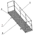
The utility model discloses a balance arm and stock platform device which comprises a stock and a balance arm, wherein a platform cross arm I is arranged on a platform frame of the balance arm platform; a steel wire gauze is paved at the bottom of the platform frame; a platform fence is arranged in a platform frame connecting sleeve, and is fixed by using a cotter pin; a clamping seat I is arranged on a balance arm side beam, and is provided with a clamping groove; a cross arm boss I is arranged at one end of the platform cross arm I, and is clamped into the clamping groove of the clamping seat I. A platform cross arm II is arranged on a platform frame of the stock platform; a steel wire gauze is paved at the bottom of the platform frame; a platform fence is arranged in a connecting sleeve of the platform frame, and is fixed by virtue of a cotter pin; a clamping seat II is arranged on a stock main body, and is provided with a clamping groove; a cross arm boss II is arranged at one end of the platform cross arm II, and is clamped into the clamping groove of the clamping seat II. By adopting the balance arm platform and stock platform device, installation of the balance arm platform, the stock platform, the balance arm and a stock is realized conveniently and rapidly, the labor intensity is effectively lowered, the working efficiency is increased, and raw materials are saved. The balance arm and stock platform device is simple in structure, high in practicability, and high in safety performance.
Description
Technical field
The utility model relates to vehicle for construction technical field, specifically a kind of platform of balance arm and cover body panel that facilitates personnel's operation and maintenance.
Background technology
At present, vehicle for construction field is with on the equilibrium arm of column foot and stock, job platform not being set mostly, if when multidigit installation personnel is gone up tower machine simultaneously and completed same work, there is inconvenience and potential safety hazard.
In order to make multidigit staff go up tower machine simultaneously, complete same work, what have is equipped with platform of balance arm on column foot equilibrium arm side bar, and cover body panel is housed on column foot stock.Platform of balance arm is evenly provided with platform stull with the bottom of the manned grid of cover body panel, can carry, and also can play the effect being connected with column foot simultaneously.And existing platform stull and the mode that mainly adopts welding or assembly being connected of column foot.If employing welding manner, tower machine moves inconvenience, and platform of balance arm and cover body panel non-dismountable.If adopt the mode of assembly, need successively platform stull according to location-to hole-wear bearing pin-wear the loaded down with trivial details operation of spring cotter, time-consuming, labour intensity and potential safety hazard are very large.
Summary of the invention
For overcoming the deficiencies in the prior art, goal of the invention of the present utility model is to provide a kind of platform of balance arm and stock stage apparatus, to realize the object that facilitates manned and quick installation.
For achieving the above object, the utility model comprises stock and equilibrium arm, it is characterized in that: platform stull one is housed on the platform framework of platform of balance arm, and the bottom of platform framework is covered with wire net, platform guardrail is contained in the adapter sleeve of platform framework, fixes with spring cotter; Deck one is contained on equilibrium arm side bar, and deck one is with draw-in groove, and one end of platform stull one is provided with stull boss one, and stull boss one snaps in the draw-in groove of deck one.
On the platform framework of cover body panel, platform stull two is housed, the bottom of platform framework is covered with wire net, and platform guardrail is contained in the adapter sleeve of platform framework, fixes with spring cotter; Deck two is contained on the main limb of stock, and deck two is with draw-in groove, and one end of platform stull two is provided with stull boss two, and stull boss two snaps in the draw-in groove of deck two; Described deck dual-purpose channel-section steel is made, for along become 120 ° to cut every two side and form with channel-section steel length direction.
The utility model is in conjunction with the actual conditions of vehicle for construction industry tower machine production at present, on equilibrium arm side bar and the main limb of stock, seat device of card is set, during installation, the stull boss of platform stull one end is inserted in deck, conveniently realized the installation of platform of balance arm and equilibrium arm, and the installation of cover body panel and stock, and need to be by other instrument and part, simple in structure, practical, not only can reduce labor intensity, can also increase work efficiency, conservation, safety performance is high.
Accompanying drawing explanation
Fig. 1 is the system architecture sketch of the utility model tower machine.
Fig. 2 is the schematic perspective view of the utility model platform of balance arm.
Fig. 3 is the schematic perspective view of the utility model cover body panel.
Fig. 4 is the axonometric drawing that platform stull one coordinates with deck one.
Fig. 5 is the axonometric drawing that platform stull two coordinates with deck two.
The specific embodiment
As shown in Figure 1, the utility model comprises stock 1 and equilibrium arm 2.
As shown in Figure 2, Figure 4 shows, on the platform framework 4 of platform of balance arm, platform stull 1 is housed, the bottom of platform framework 4 is covered with wire net 6, and platform guardrail 3 is contained in the adapter sleeve of platform framework 4, fixes with spring cotter; Deck 1 is contained on equilibrium arm side bar 8, and deck 1 is with draw-in groove, and one end of platform stull 1 is provided with stull boss 1, and stull boss 1 snaps in the draw-in groove of deck 1.The utility model is when installing platform of balance arm, 45 degree first tilt platform of balance arm, stull boss one 10 oblique cuttings of platform stull 1 are entered to be welded in the deck 1 of equilibrium arm side bar 8 sidewalls, again platform of balance arm is slowly set level, the stull boss 1 on platform stull one 5 limits has just firmly been snapped in deck 1, like this, by the gravity of platform of balance arm self, just prevent the disengaging of stull boss 1 with deck 1, realized the installation of platform of balance arm and equilibrium arm.
As shown in Fig. 3, Fig. 5, on the platform framework 4 of cover body panel, platform stull 27 is housed, the bottom of platform framework 4 is covered with wire net 6, and platform guardrail 3 is contained in the adapter sleeve of platform framework 4, fixes with spring cotter; Deck 2 13 is contained on the main limb 11 of stock, and deck 2 13 is with draw-in groove, and one end of platform stull 27 is provided with stull boss 2 12, and stull boss 2 12 snaps in the draw-in groove of deck 2 13; Described deck 2 13 use channel-section steels are made, for along become 120 ° to cut every two side and form with channel-section steel length direction.The utility model is when installation sleeve body panel, first stock platform inclination 45 is spent, platform stull 27 oblique cuttings are entered to be welded in the deck 2 13 of the main limb 11 of stock, again cover body panel is slowly set level, the stull boss 2 12 on platform stull 27 limits has just firmly been snapped in deck 2 13, like this, by the gravity of cover body panel self, just prevent the disengaging of stull boss 2 12 with deck 2 13, realized the installation of cover body panel and stock.
Claims (2)
1. a platform of balance arm and stock stage apparatus, comprise stock (1) and equilibrium arm (2), it is characterized in that: on the platform framework (4) of platform of balance arm, platform stull one (5) is housed, the bottom of platform framework (4) is covered with wire net (6), platform guardrail (3) is contained in the adapter sleeve of platform framework (4), fixes with spring cotter; It is upper that deck one (9) is contained in equilibrium arm side bar (8), and deck one (9) is with draw-in groove, and one end of platform stull one (5) is provided with stull boss one (10), and stull boss one (10) snaps in the draw-in groove of deck one (9).
2. platform of balance arm according to claim 1 and stock stage apparatus, it is characterized in that: on the platform framework (4) of cover body panel, platform stull two (7) is housed, the bottom of platform framework (4) is covered with wire net (6), platform guardrail (3) is contained in the adapter sleeve of platform framework (4), fixes with spring cotter; It is upper that deck two (13) is contained in the main limb of stock (11), and deck two (13) is with draw-in groove, and one end of platform stull two (7) is provided with stull boss two (12), and stull boss two (12) snaps in the draw-in groove of deck two (13); Channel-section steel is made for described deck two (13), for along become 120 ° to cut every two side and form with channel-section steel length direction.
Priority Applications (1)
| Application Number | Priority Date | Filing Date | Title |
|---|---|---|---|
| CN201320737687.8U CN203582338U (en) | 2013-11-21 | 2013-11-21 | Balance arm platform and stock platform device |
Applications Claiming Priority (1)
| Application Number | Priority Date | Filing Date | Title |
|---|---|---|---|
| CN201320737687.8U CN203582338U (en) | 2013-11-21 | 2013-11-21 | Balance arm platform and stock platform device |
Publications (1)
| Publication Number | Publication Date |
|---|---|
| CN203582338U true CN203582338U (en) | 2014-05-07 |
Family
ID=50580289
Family Applications (1)
| Application Number | Title | Priority Date | Filing Date |
|---|---|---|---|
| CN201320737687.8U Expired - Fee Related CN203582338U (en) | 2013-11-21 | 2013-11-21 | Balance arm platform and stock platform device |
Country Status (1)
| Country | Link |
|---|---|
| CN (1) | CN203582338U (en) |
Cited By (2)
| Publication number | Priority date | Publication date | Assignee | Title |
|---|---|---|---|---|
| CN105460814A (en) * | 2015-09-30 | 2016-04-06 | 徐州建机工程机械有限公司 | Safety protective fence of tower crane balance arm |
| CN107235425A (en) * | 2017-07-20 | 2017-10-10 | 无锡石油化工起重机有限公司 | The counter-jib of peripheral hardware extension platform is set |
-
2013
- 2013-11-21 CN CN201320737687.8U patent/CN203582338U/en not_active Expired - Fee Related
Cited By (2)
| Publication number | Priority date | Publication date | Assignee | Title |
|---|---|---|---|---|
| CN105460814A (en) * | 2015-09-30 | 2016-04-06 | 徐州建机工程机械有限公司 | Safety protective fence of tower crane balance arm |
| CN107235425A (en) * | 2017-07-20 | 2017-10-10 | 无锡石油化工起重机有限公司 | The counter-jib of peripheral hardware extension platform is set |
Similar Documents
| Publication | Publication Date | Title |
|---|---|---|
| CN104775564A (en) | Unsupported installation method for bidirectional tilting great-section box latticed columns | |
| CN203582338U (en) | Balance arm platform and stock platform device | |
| CN205591632U (en) | Pole setting device | |
| CN208415253U (en) | A kind of foundation pit anchor cable cutter | |
| CN102785243A (en) | Multi-directional regulating mechanical hand | |
| CN201891171U (en) | Integral bolt assembling frame | |
| CN203973750U (en) | Integral prefabricated T girder tensioning protection canopy | |
| CN105253325A (en) | Aircraft main landing gear assembling and disassembling equipment | |
| CN206144127U (en) | Simple and easy butt clamp integral type operation platform | |
| CN205206146U (en) | Reinforcing bar net fixed position support | |
| CN201722937U (en) | Sliding platform for installation of net rack | |
| CN204552051U (en) | The cradle structure of high-altitude crossbeam soffit monitoring point layout | |
| CN204531180U (en) | Control the stiff skeleton of large-scale component reinforcing bar binding precision | |
| CN203699828U (en) | Simple tool-type lifting frame for mounting of steel reinforcement cages | |
| CN209722779U (en) | A kind of novel traffic engineering construction wind-proof dust-suppression net | |
| CN202705932U (en) | T-beam reinforced hanger frame structure | |
| CN202388173U (en) | Forklift upper frame welding tool | |
| CN203392657U (en) | Machine maintenance platform | |
| CN203755623U (en) | Load overhauling bent frame convenient to assemble and disassemble | |
| CN203961258U (en) | Builder's jack foot guard structure | |
| CN202837084U (en) | Concrete strength rapid detection device | |
| CN203582325U (en) | Jacket frame platform clamp seat device | |
| CN201857745U (en) | Ascending operation device for H-type steel column of high-speed railway | |
| CN203582337U (en) | Balance arm platform clamping seat device | |
| CN205296988U (en) | Material covers quick assembly disassembly device |
Legal Events
| Date | Code | Title | Description |
|---|---|---|---|
| C14 | Grant of patent or utility model | ||
| GR01 | Patent grant | ||
| CF01 | Termination of patent right due to non-payment of annual fee |
Granted publication date: 20140507 Termination date: 20151121 |
|
| EXPY | Termination of patent right or utility model |