A kind of novel cable crane span structure
Technical field
The utility model belongs to cable testing bridge field, relates in particular to a kind of novel cable crane span structure.
Background technology
In recent years along with urban electricity supply is integrated, under the development trend of automation, undergroundization and miniaturization, the gas isolated metal enclosed switchgear of GIS(SF6) because its main element all packs in the canister of sealing, be filled with insulating gas, have that volume is little, floor space is few, be not affected by the external environment, safe and reliable to operation, safeguard the plurality of advantages such as simple and time between overhauls(TBO) length, good looking appearance, in transformer station, be widely adopted, for GIS provides good opportunity to develop.
GIS, as the nucleus equipment of transformer station, ensures fail safe, the reliability of its control cables, power cable, will be the basic condition that GIS equipment maintains normal operation; The laying of cable and protected mode, become the factor that GIS product needs emphasis to consider when design research and development.How on the basis of simple in structure, convenient for installation and maintenance, flexible configuration, good looking appearance practicality, to design can safety, the device of reliably protecting cable becomes one of problem of cable routing design.
In existing cable bridge device, cable tray and cable through cover are " U " font, adopt the mode of clinching to connect, and in order to improve its sealing, need to set up cable cover(ing) in outside, thereby increase the weight of whole cable testing bridge.
For guaranteeing the safe handling of supply main circuit, being grounded to as important of cable testing bridge.External device connects a copper bar conventionally in groove box, domesticly conventionally connect a zinc-plated band iron, or it is online directly the cross-over connection of groove box finally to be linked to grounding structure, and the devices such as the copper bar of setting up have not only increased the weight of cable testing bridge, and allow its more complicated not easy-maintaining.
Terminal shutoff place now a multiplex band cable is concentrated and is fixed, this makes cable relatively random, and easy-maintaining not, has also affected the overall appearance of crane span structure.
Summary of the invention
The purpose of this utility model is to provide a kind of cable testing bridge of simple in structure, convenient for installation and maintenance, flexible configuration.
For achieving the above object, the technical solution of the utility model is: a kind of novel cable crane span structure, comprise cable tray, cable through cover and terminal shutoff, cable tray inside is provided with carrying davit, described cable tray and cable through cover are all outwards provided with the first flange, cable tray is fixedly connected with by the first flange with cable through cover, and terminal shutoff is positioned at cable testing bridge end.
Upwards turn over the both sides of described terminal shutoff, forms second flange, and the limit on length direction is turned over downwards and formed the 3rd flange; Described the second flange and cable tray are bolted.
The second flange is provided with slotted hole.
Cable tray inside is provided with layering compression bonding apparatus, and described layering compression bonding apparatus is comprised of dividing plate and bolt, between two dividing plates, places one deck cable, and dividing plate top is bolted.
Two adjacent cable trays connect by plug-in type, and the part embedding at both forms a transition band, and described transition band is connected with cable tray conduction.
Described transition band outer surface is zinc-plated.
The portion of external installing banded plate that two adjacent cable trays connect.
The face that described banded plate and cable tray join is for without lacquer painting, with without the relative face of lacquer painting for there being lacquer painting.
The utility model by arranging the first flange on cable tray and cable through cover, thereby by press fastening type in the past, changing the connection of cable tray and cable through cover into first flange connects, can improve the sealing of whole cable testing bridge, thereby reduce a large amount of rainwater and enter cable testing bridge, thereby needn't re-use cable cover(ing), reduce the weight of whole cable testing bridge; By adopting plug-in type to connect two cable trays, make both at embedded part, form a transition band, this transition band and cable tray conduction are joined, and this transition band plating zinc on surface, can effectively leakage current be drawn, avoid causing danger, thereby needn't re-use jumper, also make whole cable testing bridge more attractive in appearance, simply for ease of maintenaince; By the second flange, the 3rd flange and slotted hole are set in terminal shutoff, terminal shutoff can be regulated according to the situation of cable, thereby cable is compressed, flattened, reduced gap, also make cable testing bridge more attractive in appearance.
The banded plate of setting up during cable tray level connection joint, thus the electric current in when electric leakage can be drawn and saved jumper by cable testing bridge, make whole cable testing bridge attractive in appearance, for ease of maintenaince, also reduced the weight of cable testing bridge.
accompanying drawing explanation
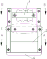
The structural representation of Fig. 1 cable testing bridge described in the utility model;
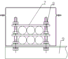
Fig. 2 is the D-D cutaway view in Fig. 1;
Fig. 3 is the A-A cutaway view in Fig. 2;
Fig. 4 is the B-B cutaway view in Fig. 2;
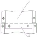
Fig. 5 is the detailed annotation figure of C portion in Fig. 4;
Fig. 6 is the structural representation of the terminal shutoff 6 in Fig. 2;
Fig. 7 is the detailed annotation figure of C portion in the Fig. 4 described in embodiment 2.
embodiment
Embodiment 1, as shown in Figure 1:
A kind of novel cable crane span structure, comprises cable tray 1, cable through cover 2, and described cable tray 1 is all with the first flange 3 with cable through cover 2.The first flange 3 and first flange 3 of cable through cover 2 of cable tray 1 are bolted, thereby realized being connected of cable tray 1 and cable through cover 2, by the connection between the first flange 3, can improve the sealing of device, reduce to greatest extent rainwater and enter.
As shown in Figure 2, Figure 3, Figure 4: in cable tray 1 inside, be provided with layering compression bonding apparatus 4 and carrying davit 5, carrying davit 5 is fixedly connected with cable tray 1, cable is fixed on carrying davit 5 and can plays certain load-bearing effect, layering compression bonding apparatus 4 is comprised of layering dividing plate 7 and connecting bolt 8, connecting bolt 8 is housed on layering dividing plate 7, between every two layering dividing plates 7, place one deck cable, on layering dividing plate 7 tops, with bolt, fix again.According to the number of plies of the actual conditions installing layering dividing plate 7 of on-site cable line, the diameter that the distance between two adjacent layering dividing plates 7 is cable.
Carrying davit 5 can play the effect of attached cable line, cable is played to certain load-bearing effect simultaneously, makes the cabling of cable in cable tray 1 more regular.
Layering compression bonding apparatus 4 can carry out layering cabling to cable, thereby makes the cabling of cable in cable tray 1 more orderly, is easy to maintenance.
Carrying davit 5 has guaranteed the safe and reliable of cable with arranging of layering compression bonding apparatus 4, makes cable routing orderly, easy to maintenance simultaneously.
As shown in Figure 5: when two cable trays 1 vertically connect, by plug-in type, connect, a cable tray 1 inserts another cable tray 1 inside, thereby forms a transition band 12, and this transition band is connected with cable tray conduction, can use a bolt that transition band is connected with cable tray, zinc on this transition band plated surface, just can realize good electric conductivity, thereby when there is leaky, electric current is derived, electromotive force is made zero, effectively avoid dangerous and occur.
Because two cable trays 1 vertically connect, can, by regulating the relative position of two cable trays 1, the gap of junction be adjusted to minimum, realize the attractive in appearance of outward appearance, improve the sealing of whole cable testing bridge.
As shown in Figure 6: the limit of terminal shutoff 6 both sides is upwards turned over and formed the second flange 9, on the second flange 9, has slotted hole 11, and cable tray 1 has screwed hole with the place that the second flange 9 is connected; According to number and the thickness of the number of plies of cable, can regulate terminal shutoff 6; When the cable number of plies is fewer and thinner, terminal shutoff 6 is pressed to cable direction, with screw or leading screw, pass the screwed hole on slotted hole 11 and cable tray 1 again, finally with nut, be fixed, by this device, cable can be flattened, reduce to greatest extent cable testing bridge and extraneous gap, effectively prevent that mouse etc. from entering cable testing bridge, makes device more attractive in appearance simultaneously.
Limit on terminal shutoff 6 length directions is turned over formation the 3rd flange 10, the three flange 10 downwards and can further be played effect neat cable repoussage when terminal shutoff 6 is pressed to cable direction, has also played certain load-bearing effect simultaneously.
Embodiment 2, as shown in Figure 7: the difference of the present embodiment and embodiment 1 is: when two cable tray level connection joints, by plug-in type, connect, a cable tray 1 inserts another cable tray 1 inside, the position being difficult for by adjusting cable tray 1 due to time connected horizontally in both junctions diminishes the gap of joint, for attractive in appearance and raising sealing, at place, gap installing banded plate 13, described banded plate 13 is fixedly connected with cable tray 1 and trailing arm support 14.
The face that banded plate 13 and cable tray 1 join is for without lacquer painting, with without the relative face of lacquer painting for there being lacquer painting.
By banded plate 13 and trailing arm support 14 have directly been connected to form to two baffles, when there is leaky, banded plate is derived electric current by trailing arm support, thereby electromotive force is made zero.
This cable testing bridge is by connecting by the first flange on cable tray and cable through cover the sealing that has improved whole cable testing bridge; When the zinc-plated transition band of two cable tray junctions can prevent from leaking electricity, cause danger, thereby needn't re-use jumper; By slotted hole is set on the second flange of terminal shutoff, make terminal shutoff cable to be compressed, to be flattened according to cable situation, realized the attractive in appearance of device, improved the sealing of cable testing bridge.