CN203513227U - Overturning device - Google Patents
Overturning device Download PDFInfo
- Publication number
- CN203513227U CN203513227U CN201320528945.1U CN201320528945U CN203513227U CN 203513227 U CN203513227 U CN 203513227U CN 201320528945 U CN201320528945 U CN 201320528945U CN 203513227 U CN203513227 U CN 203513227U
- Authority
- CN
- China
- Prior art keywords
- turning
- overturning
- rod
- hinged
- turning rod
- Prior art date
- Legal status (The legal status is an assumption and is not a legal conclusion. Google has not performed a legal analysis and makes no representation as to the accuracy of the status listed.)
- Expired - Lifetime
Links
Images


Abstract
The utility model discloses an overturning device, and relates to the technical field of machine manufacturing. The overturning device comprises at least two overturning frames which are arranged at intervals. Each overturning frame comprises a bearing platform. A first rocker arm is hinged to one side of each bearing platform through an articulated shaft in a hinged mode, wherein the first rocker arm is provided with a first overturning rod and a first pull rod connected with the first overturning rod. A second rocker arm is hinged to the other side of each bearing platform is hinged through an articulated shaft, wherein the second rocker arm is provided with a second overturning rod and a second pull rod connected with the second overturning rod. A first power cylinder and a second power cylinder are hinged to the tail end of the first pull rod and the tail end of the second pull rod. Compared with the prior art, the overturning device has the advantages that the two first rocker arms driven by the first power cylinder and the second rocker arms driven by the second power cylinder are utilized for turning over a longitudinal beam, the overturning process is stable and safe, and time and labor are saved; A traveling crane is not occupied during the overturning process, and the production efficiency is high.
Description
Technical field
The utility model relates to machining equipment manufacturing technology field, especially a kind of device for slender piece upset.
Background technology
Longeron is the important component part of automobile chassis frame, and longeron must have enough strength and stiffness to bear the load of automobile and the impact of transmitting from wheel.At present automobile longitudinal girder mainly adopts mould on oil press, to carry out die mould, and longeron is opening up, and next procedure adds man-hour,, with driving and suspender by the longeron upset of slinging, be overturn and made progress in its bottom surface; In use there is following deficiency in this upset mode: 1,, because the profile of longeron is elongated, in switching process, longeron amplitude of fluctuation is large, overturns not steady, has larger potential safety hazard; 2, the labour intensity of operating personal is large, and whole switching process will be with driving a vehicle, and production efficiency is low.
Utility model content
Technical problem to be solved in the utility model is to provide a kind of failure-free turning device swift to operate, steady, and it can solve the existing slender piece difficult problem of overturning.
In order to address the above problem, the technical solution adopted in the utility model is: this turning device, comprise at least two spaced turning racks, described turning rack is provided with supporting station, one side of described supporting station is hinged with the first rocking arm by jointed shaft, and described the first rocking arm has the first turning rod and the first pull bar being connected with described the first turning rod; The opposite side of described supporting station is hinged with the second rocking arm by jointed shaft, and described the second rocking arm has the second turning rod and the second pull bar being connected with described the second turning rod; End at described the first pull bar and described the second pull bar is hinged with respectively the first power cylinder and the second power cylinder.
In above-mentioned turning device technical scheme, technical scheme can also be more specifically: described the first turning rod and the nearly described jointed shaft of described the second turning rod place are respectively equipped with the first striker plate and the second striker plate, when described the first turning rod and described the second turning rod turn to the table top of described supporting station in vertical state, described the first striker plate and described the second striker plate are in opposite directions and arrange; Distance L between described the first turning rod and described the second turning rod is that the height h of upset workpiece adds 1 millimeter to 2 millimeters.
Further: the angle of the angle a of the table top of described supporting station and horizontal surface is 0 degree to 60 degree.
Owing to having adopted technique scheme, the utility model compared with prior art has following beneficial effect:
Turning device adopts the first rocking arm of two the first power cylinders drivings and the second rocking arm of two the second power cylinder drivings that longeron is overturn, and the steady safety of switching process is time saving and energy saving; Switching process does not take driving, and production efficiency is high.
Accompanying drawing explanation
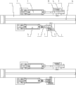
Fig. 1 is the structural representation of the utility model embodiment 1.
Fig. 2 is the birds-eye view of Fig. 1.
Fig. 3 is the schematic diagram before the slender piece of the utility model embodiment 1 overturns.
Fig. 4 is the first turning rod of the utility model embodiment 1 and the second turning rod schematic diagram while turning to the table top of supporting station in vertical state.
Fig. 5 is the schematic diagram that the slender piece of the utility model embodiment 1 completes upset.
The specific embodiment
Below in conjunction with accompanying drawing embodiment, the utility model is described in further detail:
Embodiment 1:
Automobile longitudinal girder 13 is as shown in Figure 3 the slender type workpiece that will overturn.
Turning device as shown in Figure 1 and Figure 2 comprises two parallel spaced turning racks 1, and turning rack 1 has tilting supporting station 10, and the angle of the angle a of the table top of supporting station 10 and horizontal surface is 60 degree; The equal interval, both sides of each turning rack 1 is provided with bearing 2 and strut bar 6, bearing 2 is fixed by bolts on the base plate near the tilting table top lower end of supporting station 10, strut bar 6 is welded on the base plate near the tilting table top top of supporting station 10, and the upper end of bearing 2 and strut bar 6 is equipped with hinge axis hole; One side of supporting station 10 is hinged with the first rocking arm by jointed shaft, the first rocking arm has the first turning rod 8 and the first pull bar 8-1 being connected with the first turning rod 8, in the junction of the first turning rod 8 and the first pull bar 8-1, be provided with the hinge axis hole that jointed shaft is installed, the first rocking arm was hinged between turning rack 1 and strut bar 6 by installing the jointed shaft of this hinge axis hole; The opposite side of supporting station 10 is hinged with the second rocking arm by jointed shaft, the second rocking arm has the second turning rod 7 and the second pull bar 7-1 being connected with the second turning rod 7, the junction of the second turning rod 7 and the second pull bar 7-1 is provided with the hinge axis hole that jointed shaft is installed, and the second rocking arm was hinged between turning rack 1 and strut bar 6 by installing the jointed shaft of this hinge axis hole; The second spacer 12 is all equipped with in the jointed shaft outside that be all equipped with between the first spacer 11, the first rocking arms and the second rocking arm and strut bar 6 jointed shaft outside between the first rocking arm and the second rocking arm and turning rack 1; At the first turning rod 8 and the second turning rod 7, near jointed shaft place, be welded with respectively the first striker plate 8-2 and the second striker plate 7-2, when the first turning rod 8 and the second turning rod 7 turn to the table top of supporting station 10 in vertical state, the first striker plate 8-2 and the second striker plate 7-2 are in opposite directions and arrange; Distance L between the first turning rod 8 and the second turning rod 7 is that the height h of upset workpiece adds 1 millimeter.End at the first pull bar 8-1 and the second pull bar 7-1 is equipped with hinge axis hole, and the first pull bar 8-1 is hinged with the first contiguous block 9 being contained on the piston rod of the first power cylinder 3, and the first contiguous block 9 is threaded connection with piston rod; The second pull bar 7-1 is hinged with the second contiguous block 5 being contained on the piston rod of the second power cylinder 4, and the second contiguous block 5 is threaded connection with piston rod; First power cylinder of the present embodiment and the second power cylinder are respectively the first hydraulic actuating cylinder 3 and the second hydraulic actuating cylinder 4, the first hydraulic actuating cylinders 3 and the second hydraulic actuating cylinder 4 and are hinged on respectively on the bearing 2 that is positioned at turning rack 1 both sides.
During work, automobile longitudinal girder 13 is placed on two turning racks 1 of turning device, the side that two the first rocking arms is forwarded to the first turning rod 8 is parallel with the table top of supporting station 10, and the first striker plate 8-2 is towards the position vertical with the table top of supporting station 10 that make progress; It is vertical with the table top of supporting station 10 that two the second rocking arms forward the second turning rod 7 to, the position that the upper surface of the second striker plate 7-2 is parallel with the table top of supporting station 10; On supporting station 10 table tops of longeron across the turning rack 1 be arrangeding in parallel at two, downside is near two the first striker plate 8-2, as shown in Figure 3; The piston rod that simultaneously starts 3, two the first hydraulic actuating cylinders 3 of two the first hydraulic actuating cylinders promotes the first rocking arm by the first contiguous block 9 and rotates, and two the first rocking arms drive longitudinal beam overturning 90 degree simultaneously, as shown in Figure 4; Then start two the second hydraulic actuating cylinders 4 simultaneously, the piston rod of two the second hydraulic actuating cylinders 4 promotes the second rocking arm by the second contiguous block 5 and rotates, two the second rocking arms drive longeron to turn over and turn 90 degrees again simultaneously, make the another side of longeron upwards, the piston rod of two the first hydraulic actuating cylinders 3 returns to reference position, as shown in Figure 5.
Embodiment 2:
The angle of the angle a of the table top of supporting station 10 and horizontal surface is 0 degree, and the distance L between the first turning rod 8 and the second turning rod 7 is that the height h of upset workpiece adds 2 millimeters.All the other features are identical with embodiment 1.
Claims (3)
1. a turning device, it is characterized in that: comprise at least two spaced turning racks (1), described turning rack (1) has supporting station (10), a side at described supporting station (10) is hinged with the first rocking arm by jointed shaft, and described the first rocking arm has the first turning rod (8) and the first pull bar (8-1) being connected with described the first turning rod (8); Opposite side at described supporting station (10) is hinged with the second rocking arm by jointed shaft, and described the second rocking arm has the second turning rod (7) and the second pull bar (7-1) being connected with described the second turning rod (7); End at described the first pull bar (8-1) and described the second pull bar (7-1) is hinged with respectively the first power cylinder (3) and the second power cylinder (4).
2. turning device according to claim 1, it is characterized in that: described the first turning rod (8) and the nearly described jointed shaft of described the second turning rod (7) place are respectively equipped with the first striker plate (8-2) and the second striker plate (7-2), when described the first turning rod (8) and described the second turning rod (7) turn to the table top of described supporting station (10) in vertical state, described the first striker plate (8-2) is in opposite directions and arranges with described the second striker plate (7-2); Distance L between described the first turning rod (8) and described the second turning rod (7) is that the height h of upset workpiece adds 1 millimeter to 2 millimeters.
3. according to turning device described in claim 1 or 2, it is characterized in that: the angle of the table top of described supporting station (10) and the angle a of horizontal surface is 0 degree to 60 degree.
Priority Applications (1)
| Application Number | Priority Date | Filing Date | Title |
|---|---|---|---|
| CN201320528945.1U CN203513227U (en) | 2013-08-28 | 2013-08-28 | Overturning device |
Applications Claiming Priority (1)
| Application Number | Priority Date | Filing Date | Title |
|---|---|---|---|
| CN201320528945.1U CN203513227U (en) | 2013-08-28 | 2013-08-28 | Overturning device |
Publications (1)
| Publication Number | Publication Date |
|---|---|
| CN203513227U true CN203513227U (en) | 2014-04-02 |
Family
ID=50372186
Family Applications (1)
| Application Number | Title | Priority Date | Filing Date |
|---|---|---|---|
| CN201320528945.1U Expired - Lifetime CN203513227U (en) | 2013-08-28 | 2013-08-28 | Overturning device |
Country Status (1)
| Country | Link |
|---|---|
| CN (1) | CN203513227U (en) |
Cited By (1)
| Publication number | Priority date | Publication date | Assignee | Title |
|---|---|---|---|---|
| CN103420314A (en) * | 2013-08-28 | 2013-12-04 | 东风柳州汽车有限公司 | Turnover device |
-
2013
- 2013-08-28 CN CN201320528945.1U patent/CN203513227U/en not_active Expired - Lifetime
Cited By (2)
| Publication number | Priority date | Publication date | Assignee | Title |
|---|---|---|---|---|
| CN103420314A (en) * | 2013-08-28 | 2013-12-04 | 东风柳州汽车有限公司 | Turnover device |
| CN103420314B (en) * | 2013-08-28 | 2016-11-09 | 东风柳州汽车有限公司 | Turning device |
Similar Documents
| Publication | Publication Date | Title |
|---|---|---|
| CN201756337U (en) | 90 degree cylinder turnover mechanism | |
| CN203316956U (en) | Automobile front wheel cover assembly welding jig | |
| CN202780364U (en) | Welding, turning and shifting jig for crane trolley frame | |
| CN202106181U (en) | Clamp for automobile floor welding | |
| CN202053051U (en) | Vehicle frame turnover device | |
| CN202541672U (en) | Movable tool for vehicle door installation | |
| CN203566112U (en) | Stripping mechanism applied to welding line | |
| CN203356914U (en) | Semitrailer frame crossbeam assembly welding table | |
| CN102009305A (en) | Frame assembly production line and use method thereof | |
| CN201889613U (en) | Splicing production line for vehicle frame | |
| CN203513227U (en) | Overturning device | |
| CN103420314A (en) | Turnover device | |
| CN203448907U (en) | Dumper platform floor welding table | |
| CN202006344U (en) | Welding clamp lifting mechanism | |
| CN201817237U (en) | Gantry tilting device for forklifts and forklift provided with gantry tilting device | |
| CN203568689U (en) | Steel structure for wall-sleeving cantilever crane | |
| CN205764533U (en) | It is provided with the portal welder device of straddle truck | |
| CN203513123U (en) | Special turnover machine for passenger-carrying chassis frame | |
| CN2866026Y (en) | Driver's cab proenclose station appliances | |
| CN202610373U (en) | Hanging bracket for gantry cathode electrophoresis coating production line | |
| CN203319649U (en) | Lifting mechanism of forklift truck | |
| CN208304261U (en) | The assist formation device of guardrail after a kind of automobile | |
| CN203624566U (en) | Nut supply device of nut automatic welding machine | |
| CN203448908U (en) | Welding table for welding of auxiliary dumper frame | |
| CN203062100U (en) | Lifting working table frame |
Legal Events
| Date | Code | Title | Description |
|---|---|---|---|
| C14 | Grant of patent or utility model | ||
| GR01 | Patent grant |