CN203511775U - Auxiliary frame structure - Google Patents
Auxiliary frame structure Download PDFInfo
- Publication number
- CN203511775U CN203511775U CN201320541283.1U CN201320541283U CN203511775U CN 203511775 U CN203511775 U CN 203511775U CN 201320541283 U CN201320541283 U CN 201320541283U CN 203511775 U CN203511775 U CN 203511775U
- Authority
- CN
- China
- Prior art keywords
- auxiliary frame
- lateral stability
- frame structure
- subframe body
- oscillating arm
- Prior art date
- Legal status (The legal status is an assumption and is not a legal conclusion. Google has not performed a legal analysis and makes no representation as to the accuracy of the status listed.)
- Expired - Fee Related
Links
Images

Abstract
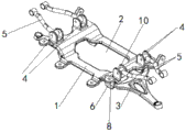
The utility model provides an auxiliary frame structure applied to the technical field of automobile parts. The auxiliary frame structure comprises an auxiliary frame body (1), wherein the auxiliary frame body (1) is of a plate structure with an open hole part (2) arranged in the middle, a swing arm (3) is fixedly connected with one end of the auxiliary frame body (1), transverse stabilization pull rod supports (4) are arranged on the auxiliary frame body (1), and transverse stabilization pull rods (5) are movably connected with the transverse stabilization pull rod supports (4). The auxiliary frame structure can effectively reduce product weight and has high carrying strength and bending resisting rigidity. Compared with a traditional auxiliary frame of a steel plate structure, the auxiliary frame structure reduces accumulated errors generated in part assembling and improves product precision.
Description
Technical field
The utility model belongs to technical field of automobile parts, more particularly, relates to a kind of auxiliary frame structure.
Background technology
At present, subframe all adopts after steel plate punched moulding welded structure again, and this subframe weight is larger, particularly the course continuation mileage of pure electric automobile is had to serious restriction.The subframe of steel plate punched molding structure need drop into a lot of moulds simultaneously, and die cost is very high, has directly improved vehicle manufacturing cost.
Utility model content
Technical problem to be solved in the utility model is: for the deficiencies in the prior art, provide that a kind of quality is little, rigidity is large, precision is high, be particularly suitable for the auxiliary frame structure of electronlmobil.
Solve above-described technical matters, the technical scheme that the utility model is taked is:
The utility model is a kind of auxiliary frame structure, comprise subframe body, the plate structure of aperture portion in the middle of being set to, described subframe body is set, subframe body one end is fixedly connected with swing arm, lateral stability rob support is set on subframe body, and lateral stability pull bar is flexibly connected with lateral stability rob support.
Preferably, described subframe body is fixedly connected with a plurality of oscillating arm brackets, and swing arm is fixedly connected with oscillating arm bracket.
Preferably, described subframe body bottom arranges two oscillating arm brackets, and each is comprised of each oscillating arm bracket two plate I, and swing arm two ends are respectively fixedly connected with two oscillating arm brackets by a set pin I.
Preferably, described subframe body top arranges two lateral stability rob supports, and each is comprised of each lateral stability rob support two plate II, and lateral stability pull bar two ends are flexibly connected with two lateral stability rob supports by a set pin II respectively.
Preferably, described subframe body, oscillating arm bracket, swing arm, lateral stability rob support, lateral stability pull bar is by aluminum alloy materials casting or forging or machining mode machine-shaping.
Adopt the technical solution of the utility model, can obtain following beneficial effect:
Auxiliary frame structure of the present utility model, subframe body, oscillating arm bracket, lateral stability rob support is integral formula structure, above-mentioned each parts entirely by aluminum alloy materials by casting or forging or machining mode machine-shaping.Can effectively reduce product weight like this, make auxiliary frame structure there is very high loading strength and counter-bending rigidity simultaneously; Meanwhile, in auxiliary frame structure of the present utility model, at the position that the requirement of strength of auxiliary frame structure is high, pass through local thickened material thickness, the further like this intensity that improves vehicle frame.Compare with conventional steel plates structure subframe, structure decrease of the present utility model the cumulative errors that produce of parts assemblings, improved Product Precision.In the utility model, the material of swing arm and lateral stability pull bar is also to process with high strength aluminum alloy, swing arm and lateral stability pull bar bearing capacity in Vehicle Driving Cycle are larger, by casting or forging or machining mode machine-shaping change materials microstructure, enhance product performance.
Accompanying drawing explanation
The expressed content of each accompanying drawing of this specification sheets and the mark in figure are made to brief description below:
Fig. 1 is the integral structure schematic diagram of auxiliary frame structure described in the utility model;
Fig. 2 is the plan structure schematic diagram of the auxiliary frame structure described in Fig. 1;
Fig. 3 is the structural representation of looking up of auxiliary frame structure described in Fig. 1;
Accompanying drawing acceptance of the bid note is respectively: 1, subframe body; 2, aperture portion; 3, swing arm; 4, lateral stability rob support; 5, lateral stability pull bar; 6, oscillating arm bracket; 7, plate I; 8, set pin I; 9, plate II; 10, set pin II.
The specific embodiment
Contrast accompanying drawing below, by the description to embodiment, the specific embodiment of the present utility model is described in further detail as the effect of the mutual alignment between the shape of each related member, structure, each several part and annexation, each several part and principle of work etc.:
As shown in accompanying drawing 1-accompanying drawing 3, the utility model is a kind of auxiliary frame structure, comprise subframe body 1, the plate structure of aperture portion 2 in the middle of being set to, described subframe body 1 is set, subframe body 1 one end is fixedly connected with swing arm 3, lateral stability rob support 4 is set on subframe body 1, and described lateral stability pull bar 5 is flexibly connected with lateral stability rob support 4.
Preferably, described subframe body 1 is fixedly connected with a plurality of oscillating arm brackets 6, and swing arm 3 is fixedly connected with oscillating arm bracket 6.
Preferably, described subframe body 1 bottom arranges two oscillating arm brackets 6, and each oscillating arm bracket 6 is respectively comprised of two plate I 7, and swing arm 3 two ends are respectively fixedly connected with two oscillating arm brackets 6 by a set pin I 8.
Preferably, described subframe body 1 top arranges two lateral stability rob supports 4, each lateral stability rob support 4 is respectively comprised of two plate II 9, and lateral stability pull bar 5 two ends are flexibly connected with two lateral stability rob supports 4 by a set pin II 10 respectively.
Preferably, described subframe body 1, oscillating arm bracket 6, swing arm 3, lateral stability rob support 4, lateral stability pull bar 5 is by aluminum alloy materials casting or forging or machining mode machine-shaping.
Auxiliary frame structure of the present utility model, subframe body, oscillating arm bracket, lateral stability rob support is integral formula structure, above-mentioned each parts entirely by aluminum alloy materials by casting or forging or machining mode machine-shaping.Can effectively reduce product weight like this, make auxiliary frame structure there is very high loading strength and counter-bending rigidity simultaneously; Meanwhile, in auxiliary frame structure of the present utility model, at the position that the requirement of strength of auxiliary frame structure is high, pass through local thickened material thickness, the further like this intensity that improves vehicle frame.Compare with conventional steel plates structure subframe, structure decrease of the present utility model the cumulative errors that produce of parts assemblings, improved Product Precision.In the utility model, the material of swing arm and lateral stability pull bar is also to process with high strength aluminum alloy, swing arm and lateral stability pull bar bearing capacity in Vehicle Driving Cycle are larger, by casting or forging or machining mode machine-shaping change materials microstructure, enhance product performance.
By reference to the accompanying drawings the utility model has been carried out to exemplary description above; obviously the concrete realization of the utility model is not subject to the restrictions described above; as long as the various improvement that adopted method design of the present utility model and technical scheme to carry out; or without improving, design of the present utility model and technical scheme are directly applied to other occasions, all in protection domain of the present utility model.
Claims (5)
1. an auxiliary frame structure, comprise subframe body (1), it is characterized in that: the plate structure that aperture portion (2) are set in the middle of described subframe body (1) is set to, subframe body (1) one end is fixedly connected with swing arm (3), lateral stability rob support (4) is set on subframe body (1), and described lateral stability pull bar (5) is flexibly connected with lateral stability rob support (4).
2. auxiliary frame structure according to claim 1, is characterized in that: described subframe body (1) is fixedly connected with a plurality of oscillating arm brackets (6), and swing arm (3) is fixedly connected with oscillating arm bracket (6).
3. auxiliary frame structure according to claim 2, it is characterized in that: described subframe body (1) bottom arranges two oscillating arm brackets (6), each is comprised of each oscillating arm bracket (6) two plate I (7), and swing arm (3) two ends are respectively fixedly connected with two oscillating arm brackets (6) by a set pin I (8).
4. according to the auxiliary frame structure described in claim 2 or 3, it is characterized in that: described subframe body (1) top arranges two lateral stability rob supports (4), each is comprised of each lateral stability rob support (4) two plate II (9), and lateral stability pull bar (5) two ends are flexibly connected with two lateral stability rob supports (4) by a set pin II (10) respectively.
5. auxiliary frame structure according to claim 4, it is characterized in that: described subframe body (1), oscillating arm bracket (6), swing arm (3), lateral stability rob support (4), lateral stability pull bar (5) is by aluminum alloy materials casting or forging or machining mode machine-shaping.
Priority Applications (1)
| Application Number | Priority Date | Filing Date | Title |
|---|---|---|---|
| CN201320541283.1U CN203511775U (en) | 2013-09-02 | 2013-09-02 | Auxiliary frame structure |
Applications Claiming Priority (1)
| Application Number | Priority Date | Filing Date | Title |
|---|---|---|---|
| CN201320541283.1U CN203511775U (en) | 2013-09-02 | 2013-09-02 | Auxiliary frame structure |
Publications (1)
| Publication Number | Publication Date |
|---|---|
| CN203511775U true CN203511775U (en) | 2014-04-02 |
Family
ID=50370751
Family Applications (1)
| Application Number | Title | Priority Date | Filing Date |
|---|---|---|---|
| CN201320541283.1U Expired - Fee Related CN203511775U (en) | 2013-09-02 | 2013-09-02 | Auxiliary frame structure |
Country Status (1)
| Country | Link |
|---|---|
| CN (1) | CN203511775U (en) |
Cited By (4)
| Publication number | Priority date | Publication date | Assignee | Title |
|---|---|---|---|---|
| CN104773205A (en) * | 2015-03-10 | 2015-07-15 | 奇瑞汽车股份有限公司 | Auxiliary frame |
| CN107933692A (en) * | 2017-10-13 | 2018-04-20 | 芜湖禾田汽车工业有限公司 | Frame-type aluminum alloy auxiliary vehicle frame and preparation method thereof |
| CN107963128A (en) * | 2017-11-24 | 2018-04-27 | 芜湖禾田汽车工业有限公司 | Tower structure Welded subframe |
| CN107971703A (en) * | 2017-11-24 | 2018-05-01 | 芜湖禾田汽车工业有限公司 | The processing method of tower structure Welded subframe |
-
2013
- 2013-09-02 CN CN201320541283.1U patent/CN203511775U/en not_active Expired - Fee Related
Cited By (5)
| Publication number | Priority date | Publication date | Assignee | Title |
|---|---|---|---|---|
| CN104773205A (en) * | 2015-03-10 | 2015-07-15 | 奇瑞汽车股份有限公司 | Auxiliary frame |
| CN104773205B (en) * | 2015-03-10 | 2018-06-29 | 奇瑞汽车股份有限公司 | A kind of subframe |
| CN107933692A (en) * | 2017-10-13 | 2018-04-20 | 芜湖禾田汽车工业有限公司 | Frame-type aluminum alloy auxiliary vehicle frame and preparation method thereof |
| CN107963128A (en) * | 2017-11-24 | 2018-04-27 | 芜湖禾田汽车工业有限公司 | Tower structure Welded subframe |
| CN107971703A (en) * | 2017-11-24 | 2018-05-01 | 芜湖禾田汽车工业有限公司 | The processing method of tower structure Welded subframe |
Similar Documents
| Publication | Publication Date | Title |
|---|---|---|
| CN203511775U (en) | Auxiliary frame structure | |
| CN201969750U (en) | Bending die for plate bending machine | |
| CN101722266A (en) | Hook swing-type mold-locking mechanism with symmetric cylinders | |
| CN201644750U (en) | Die-casting mould | |
| CN201676952U (en) | Punching machine for automobile shock absorber knuckle brackets | |
| CN201901174U (en) | Front independent suspension steering joint of light bus | |
| CN202984552U (en) | Triangular hub type forging piece closed type pre-forging die structure | |
| CN203109170U (en) | Sand core outer suspension core bar device | |
| CN202508232U (en) | Entire stamping frame of bicycle | |
| CN203567473U (en) | Forklift drive axle integrated axle housing assembly | |
| CN207657168U (en) | A kind of punching molding integration mold | |
| CN202951846U (en) | Continuous casting molding machine of rotary castings | |
| CN202411714U (en) | Adhesion type car door mounting tool | |
| CN202779478U (en) | Bend mould | |
| CN203002931U (en) | Forming mold used for automobile back shaft support assembly trailing arm beam | |
| CN201952735U (en) | Shaping mold for fast manufacturing steel reinforcement cage | |
| CN102430606A (en) | Once-forming extruding machine for tubular axle blank of heavy truck | |
| CN201873466U (en) | Cathode pole boom mechanism | |
| CN202052844U (en) | Three-station punching machine | |
| CN103482462A (en) | Spool lifting tool device | |
| CN201941125U (en) | Tail plate of injection molding machine | |
| CN206139807U (en) | Pressure system of penetrating of squeeze casting machine | |
| CN206925262U (en) | New double step workpiece forging apparatus | |
| CN205085163U (en) | Extrusion formula mould | |
| CN205364163U (en) | Compound sound absorption and insulation board's of concrete mold processing for sound barrier |
Legal Events
| Date | Code | Title | Description |
|---|---|---|---|
| C14 | Grant of patent or utility model | ||
| GR01 | Patent grant | ||
| C41 | Transfer of patent application or patent right or utility model | ||
| TR01 | Transfer of patent right |
Effective date of registration: 20151022 Address after: 321300 No. 9 Beihu Road, Yongkang Economic Development Zone, Zhejiang, China Patentee after: Zhejiang Zhongtai Automobile Manufacturing Co., Ltd. Address before: 321301 Yongkang City, Jinhua Province Hardware Science and Technology Industrial Park, North Lake Road, No. 1 Patentee before: Zotye Holding Group Co., Ltd. |
|
| CF01 | Termination of patent right due to non-payment of annual fee |
Granted publication date: 20140402 Termination date: 20200902 |
|
| CF01 | Termination of patent right due to non-payment of annual fee |