CN203476553U - Air inlet manifold structure - Google Patents
Air inlet manifold structure Download PDFInfo
- Publication number
- CN203476553U CN203476553U CN201320593702.6U CN201320593702U CN203476553U CN 203476553 U CN203476553 U CN 203476553U CN 201320593702 U CN201320593702 U CN 201320593702U CN 203476553 U CN203476553 U CN 203476553U
- Authority
- CN
- China
- Prior art keywords
- egr
- waste gas
- air inlet
- egr waste
- inlet manifold
- Prior art date
- Legal status (The legal status is an assumption and is not a legal conclusion. Google has not performed a legal analysis and makes no representation as to the accuracy of the status listed.)
- Expired - Fee Related
Links
Images


Classifications
-
- Y—GENERAL TAGGING OF NEW TECHNOLOGICAL DEVELOPMENTS; GENERAL TAGGING OF CROSS-SECTIONAL TECHNOLOGIES SPANNING OVER SEVERAL SECTIONS OF THE IPC; TECHNICAL SUBJECTS COVERED BY FORMER USPC CROSS-REFERENCE ART COLLECTIONS [XRACs] AND DIGESTS
- Y02—TECHNOLOGIES OR APPLICATIONS FOR MITIGATION OR ADAPTATION AGAINST CLIMATE CHANGE
- Y02T—CLIMATE CHANGE MITIGATION TECHNOLOGIES RELATED TO TRANSPORTATION
- Y02T10/00—Road transport of goods or passengers
- Y02T10/10—Internal combustion engine [ICE] based vehicles
- Y02T10/12—Improving ICE efficiencies
Abstract
The utility model relates to the field of engine inlet air circulation, in particular to an air inlet manifold structure. The air inlet manifold structure comprises an air inlet manifold body, an EGR valve installation end face, an EGR waste gas inlet, an EGR diversion channel and an EGR waste gas outlet, and the EGR valve installation end face, the EGR waste gas inlet, the EGR diversion channel and the EGR waste gas outlet are arranged according to the air flow order. The air inlet manifold structure is characterized in that the air inlet manifold structure further comprises an EGR waste gas mixed connecting pipe and an air inlet connecting pipe, after being installed at the EGR waste gas outlet, the EGR waste gas mixed connecting pipe is connected with the air inlet connecting pipe and stretches into the air inlet connecting pipe and the air inlet connecting pipe is communicated with the air inlet manifold body. The air inlet manifold structure improves the uniformity of the EGR rates of all cylinders, the emission of nitric oxide will be greatly reduced, the emission of a complete machine can meet design requirements, and meanwhile the arrangement space of the complete machine is saved.
Description
Technical field
The utility model relates to engine charge cycle art, relates to specifically a kind of admission manifold branch structure.
Background technique
Novel diesel engine, in order to meet more and more harsh emissions requirements, can be arranged gas recirculation system, conventionally to reduce the generation of nitrogen oxide in effulent in complete machine.Common gas recirculation system is comprised of parts such as exhaust gas recirculation valve, EGR suction tude, EGR steam outlet pipes conventionally, its function is mainly that the waste gas that comprises the nitrogen oxide producing under high-temperature oxygen-enriched condition is again introduced in gas handling system and burnt, the maximum temperature that makes to burn reduces, to reduce the generation of nitrogen oxide.But be in fact subject to the structure influence of general intake manifold, the introducing of waste gas can not fully mix with fresh air, the uniformity that each cylinder EGR leads can be very poor, this can cause EGR to lead high cylinder particle emission increases, and EGR leads low cylinder discharged nitrous oxides rising, finally cause the discharge of diesel engine not reach designing requirement, this has just lost the meaning of introducing gas recirculation system.
Model utility content
The purpose of this utility model is to address the above problem, and a kind of admission manifold branch structure is provided.
In order to realize the purpose of this utility model, the technical solution adopted in the utility model is:
A kind of admission manifold branch structure, comprise intake manifold body, EGR valve is installed end face, EGR waste gas inlet, EGR guide channel, EGR waste gas air outlet, according to air-flow, be disposed in order EGR valve end face, EGR waste gas inlet, EGR guide channel, EGR waste gas air outlet are installed, it is characterized in that: also comprise that EGR waste gas mixes adapter, air inlet tube, EGR waste gas mixes adapter and is arranged on behind EGR waste gas air outlet, EGR waste gas mixes to take over and connects air inlet tube and extend into air inlet tube inside, and air inlet tube is communicated with intake manifold body.
It is integrated as a whole that EGR valve is installed end face, EGR waste gas inlet, EGR guide channel, EGR waste gas air outlet, EGR waste gas mixing adapter, air inlet tube, intake manifold body.
The beneficial effects of the utility model are: EGR guide channel mixes the introducing of taking over EGR waste gas makes waste gas can mix more fully with fresh air, improved the uniformity that each cylinder EGR leads, nitrogen oxide discharge capacity will reduce greatly, complete machine discharge can be met design requirement, gas recirculation system is integrated in intake manifold, thereby make EGR valve can be directly installed in intake manifold, saved the connecting pipeline in gas recirculation system, make complete machine structure compacter, saved complete machine arrangement space.
Accompanying drawing explanation
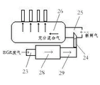
Fig. 1 is intake manifold and egr system pipeline structure schematic diagram before improving,
Fig. 2 is the utility model and egr system pipeline structure schematic diagram after improving,
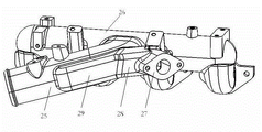
Fig. 3 is the utility model structural representation,
Fig. 4 is the exploded enlarged view in Fig. 3,
Air-flow schematic flow sheet when Fig. 5 is the utility model working state.
Embodiment
Below in conjunction with drawings and Examples, the utility model is further illustrated:
Embodiment: referring to Fig. 1, Fig. 2, Fig. 3, Fig. 4, Fig. 5.
A kind of admission manifold branch structure, comprise intake manifold body 26, EGR valve is installed end face 27, EGR waste gas inlet 23, EGR guide channel 28, EGR waste gas air outlet 29, according to air-flow, be disposed in order EGR valve end face 27 is installed, EGR waste gas inlet 23, EGR guide channel 28, EGR waste gas air outlet 29, it is characterized in that: also comprise that EGR waste gas mixes adapter 24, air inlet tube 25, EGR waste gas mixes adapter 24 and is arranged on behind EGR waste gas air outlet 29, EGR waste gas mixes to be taken over 24 connection air inlet tubes 25 and extend into air inlet tube 25 inside, air inlet tube 25 is communicated with intake manifold body 26.
EGR valve install end face 27, EGR waste gas inlet 23, EGR guide channel 28, EGR waste gas air outlet 29, EGR waste gas mix take over 24, air inlet tube 25, intake manifold body 26 be integrated as a whole.
Specification: the intake manifold before former improvement and egr system line arrangement comprise EGR valve 12, EGR waste gas steam outlet pipe 14, intake manifold 16, air inlet tube 15, EGR exhaust inlet pipe 11, EGR valve fixed support 13, and systematic part is more.Waste gas generates through vent systems, by introducing cylinder combustion after EGR exhaust inlet pipe 11 → EGR valve 12 → EGR waste gas steam outlet pipe 14 → air inlet tube 15 → intake manifold 16, not through fully mixing with fresh air, in four cylinders, the composition of air inlet is affected, some cylinder waste gas contents are more, some cylinder fresh airs are more, and this will cause that each cylinder EGR leads inhomogeneous.EGR leads high cylinder particulate emission and raises, and EGR leads the discharge rising of low cylinder nitrogen oxide, finally causes complete machine discharge not reach designing requirement.
Model utility admission manifold branch structure and egr system line arrangement after improvement comprise intake manifold body 26, EGR valve is installed end face 27, EGR waste gas inlet 23, EGR guide channel 28, EGR waste gas air outlet 29, EGR waste gas mixes takes over 24, air inlet tube 25, waste gas generates through vent systems, by EGR exhaust inlet pipe → EGR valve → the utility model admission manifold branch structure.In system layout, reduce like this design of EGR valve fixed support, EGR waste gas steam outlet pipe, air inlet tube, saved complete machine arrangement space.Although admission manifold branch structure is more complicated than original, with existing Tool and Die Technology, by the mode of core assembly and mould assembling cast, still can well the mud core of inner chamber be removed.What conventionally adopt due to former EGR waste gas steam outlet pipe is stainless-steel pipe material simultaneously, and from cost angle, stainless steel is higher much than cast aluminium, so the utility model inlet manifold system is set up more and has superiority at cost and cloth.
The utility model admission manifold branch structure makes the waste gas of discharging from gas exhaust manifold enter EGR waste gas by EGR waste gas air outlet 23 to mix and take over 24 and mix with the fresh air from after charge inter cooling, because EGR waste gas mixing adapter 24 layouts that stretch in air inlet tube 25 can be so that waste gas mixes with fresh air fully, mixing air is inhaled into each cylinder and burns, after mixing, the air inlet composition of each cylinder is close, therefore guaranteed the uniformity that each cylinder EGR leads, in products of combustion, the content of nitrogen oxide and particulate emission can reduce, final complete machine discharge can meet design requirement.Secondly, by EGR valve, through EGR waste gas inlet 23, enter EGR guide channel 28, guide channel structure can reduce intake resistance greatly.
What embodiment of the present utility model announced is preferred embodiment; but be not limited to this; those of ordinary skill in the art; very easily according to above-described embodiment; understand spirit of the present utility model; and make different amplifications and variation, but only otherwise depart from spirit of the present utility model, all in protection domain of the present utility model.
Claims (2)
1. an admission manifold branch structure, comprise intake manifold body, EGR valve is installed end face, EGR waste gas inlet, EGR guide channel, EGR waste gas air outlet, according to air-flow, be disposed in order EGR valve end face, EGR waste gas inlet, EGR guide channel, EGR waste gas air outlet are installed, it is characterized in that: also comprise that EGR waste gas mixes adapter, air inlet tube, EGR waste gas mixes adapter and is arranged on behind EGR waste gas air outlet, EGR waste gas mixes to take over and connects air inlet tube and extend into air inlet tube inside, and air inlet tube is communicated with intake manifold body.
2. a kind of admission manifold branch structure according to claim 1, is characterized in that: it is integrated as a whole that EGR valve is installed end face, EGR waste gas inlet, EGR guide channel, EGR waste gas air outlet, EGR waste gas mixing adapter, air inlet tube, intake manifold body.
Priority Applications (1)
| Application Number | Priority Date | Filing Date | Title |
|---|---|---|---|
| CN201320593702.6U CN203476553U (en) | 2013-09-25 | 2013-09-25 | Air inlet manifold structure |
Applications Claiming Priority (1)
| Application Number | Priority Date | Filing Date | Title |
|---|---|---|---|
| CN201320593702.6U CN203476553U (en) | 2013-09-25 | 2013-09-25 | Air inlet manifold structure |
Publications (1)
| Publication Number | Publication Date |
|---|---|
| CN203476553U true CN203476553U (en) | 2014-03-12 |
Family
ID=50224893
Family Applications (1)
| Application Number | Title | Priority Date | Filing Date |
|---|---|---|---|
| CN201320593702.6U Expired - Fee Related CN203476553U (en) | 2013-09-25 | 2013-09-25 | Air inlet manifold structure |
Country Status (1)
| Country | Link |
|---|---|
| CN (1) | CN203476553U (en) |
Cited By (5)
| Publication number | Priority date | Publication date | Assignee | Title |
|---|---|---|---|---|
| CN106677932A (en) * | 2017-01-25 | 2017-05-17 | 宁波神通模塑有限公司 | EGR mixing and distributing pipe of plastic gas inlet manifold |
| JP2017096176A (en) * | 2015-11-25 | 2017-06-01 | アイシン精機株式会社 | Intake device of internal combustion engine |
| CN106812634A (en) * | 2017-01-25 | 2017-06-09 | 宁波神通模塑有限公司 | Integrated EGR valve structure on a kind of plastic air intake manifold |
| CN109826730A (en) * | 2019-03-25 | 2019-05-31 | 安徽华菱汽车有限公司 | A kind of automobile and its inlet duct |
| CN110259609A (en) * | 2019-05-31 | 2019-09-20 | 广西玉柴机器股份有限公司 | A kind of air inlet pipe of integrated EGR channel |
-
2013
- 2013-09-25 CN CN201320593702.6U patent/CN203476553U/en not_active Expired - Fee Related
Cited By (7)
| Publication number | Priority date | Publication date | Assignee | Title |
|---|---|---|---|---|
| JP2017096176A (en) * | 2015-11-25 | 2017-06-01 | アイシン精機株式会社 | Intake device of internal combustion engine |
| CN106677932A (en) * | 2017-01-25 | 2017-05-17 | 宁波神通模塑有限公司 | EGR mixing and distributing pipe of plastic gas inlet manifold |
| CN106812634A (en) * | 2017-01-25 | 2017-06-09 | 宁波神通模塑有限公司 | Integrated EGR valve structure on a kind of plastic air intake manifold |
| CN106677932B (en) * | 2017-01-25 | 2022-09-13 | 神通科技集团股份有限公司 | EGR (exhaust gas recirculation) mixed distribution pipe of plastic intake manifold |
| CN109826730A (en) * | 2019-03-25 | 2019-05-31 | 安徽华菱汽车有限公司 | A kind of automobile and its inlet duct |
| CN109826730B (en) * | 2019-03-25 | 2024-02-09 | 安徽华菱汽车有限公司 | Automobile and air inlet device thereof |
| CN110259609A (en) * | 2019-05-31 | 2019-09-20 | 广西玉柴机器股份有限公司 | A kind of air inlet pipe of integrated EGR channel |
Similar Documents
| Publication | Publication Date | Title |
|---|---|---|
| CN203476553U (en) | Air inlet manifold structure | |
| CN206530418U (en) | EGR valve and engine EGR system for engine EGR system | |
| CN203499859U (en) | Supercharged diesel engine Venturi tube exhaust gas recirculation apparatus | |
| CN202125382U (en) | Gas inlet tube of diesel engine | |
| CN103670833A (en) | Air intake manifold of diesel engine | |
| CN202348499U (en) | Inlet manifold for integrated exhaust gas recirculation (EGR) exhaust gas channel | |
| CN202789203U (en) | Connecting pipe and exhaust gas recirculation (EGR) system using the same | |
| CN202273776U (en) | Exhaust gas recirculation (EGR) structure of diesel engine | |
| CN202645779U (en) | Diesel engine exhaust gas recirculation mixer | |
| CN205172763U (en) | EGR (exhaust gas recirculation) system | |
| CN204299729U (en) | A kind of waste gas circulation tubular construction | |
| CN205225496U (en) | Realize cold, controllable introducing device of hot EGR | |
| CN102953867A (en) | Engine air inlet pipe | |
| CN109488490B (en) | Mixing structure of engine exhaust gas recirculation system | |
| CN203717168U (en) | Engine, as well as exhaust gas recirculation system and exhaust manifold thereof | |
| CN202946266U (en) | Gas mixer for internal combustion engine | |
| CN203452934U (en) | EGR mixer of exhaust gas recirculation diesel engine | |
| CN201794690U (en) | Gas inlet pipe of diesel engine | |
| CN103541835A (en) | Turbocharged engine with cooling exhaust recirculation technology | |
| CN202228228U (en) | Air inlet pipe of engine | |
| CN203335279U (en) | Natural gas mixer | |
| CN203009103U (en) | Exhaust gas distributing mechanism for exhaust gas recirculation system of diesel engine | |
| CN203296966U (en) | Separate EGR (exhaust gas recirculation) system of diesel engine | |
| CN202500678U (en) | EGR air inlet structure | |
| CN201756993U (en) | Engine exhaust manifold |
Legal Events
| Date | Code | Title | Description |
|---|---|---|---|
| GR01 | Patent grant | ||
| GR01 | Patent grant | ||
| CF01 | Termination of patent right due to non-payment of annual fee | ||
| CF01 | Termination of patent right due to non-payment of annual fee |
Granted publication date: 20140312 Termination date: 20200925 |