CN203450235U - Electric tractor chassis - Google Patents
Electric tractor chassis Download PDFInfo
- Publication number
- CN203450235U CN203450235U CN201320587460.XU CN201320587460U CN203450235U CN 203450235 U CN203450235 U CN 203450235U CN 201320587460 U CN201320587460 U CN 201320587460U CN 203450235 U CN203450235 U CN 203450235U
- Authority
- CN
- China
- Prior art keywords
- vehicle frame
- battery
- chassis
- drive
- drive motor
- Prior art date
- Legal status (The legal status is an assumption and is not a legal conclusion. Google has not performed a legal analysis and makes no representation as to the accuracy of the status listed.)
- Expired - Fee Related
Links
Images


Abstract
The utility model relates to the field of agricultural machinery, and particularly relates to an electric tractor chassis. The electric tractor chassis comprises a tractor frame, walking systems, a power source system, a power transmission system and an electric lifting device, wherein the walking systems are positioned at two sides of the tractor frame; the power source system is positioned on the upper part of the tractor frame; the electric lifting device is positioned on one end of the tractor frame, and is connected with the power source system. A pure electric power transmission system is adopted for the electric tractor chassis structure provided by the utility model; electricity energy required for a driving motor and a lifting motor is provided by a power battery; the rotation speed of the driving motor is controlled through a driving motor controller so as to meet the power required for a tractor under different operation working conditions; according to different operation working condition requirements, the rotation speed of the lifting motor is controlled through the lifting motor controller so as to achieve the ascending and descending of a rear suspension and agricultural machinery or meet a certain tilling depth requirement; the electric tractor chassis has the advantages of infinite speed variation, no pollution, small noise, good controllability and the like.
Description
Technical field
The utility model relates to field of agricultural machinery, relates in particular to a kind of plough that is applicable to facility plastic greenhouse in agricultural production, ploughs, the battery-powered tractor chassis of the agro-farming operation such as sowing.
Background technology
Minitype wheeled tractor is the Tractor Products most with China domestic characteristic, since starting stock production the seventies from twentieth century, gone through more than 40 year and lasting, in recent years year volume of production and marketing all 800,000 left and right.Why minitype wheeled tractor product so continues strong sales, is because its products characteristics meets the situation of country and people, adapts to the present situation in rural area, embodies peasant's demand.But at present China's minitype wheeled tractor exists that fuel oil consumption is large, operating efficiency is low, handle effort, noise is high, do not meet the defects such as meticulous farmland operation.
Small-sized electric trac. is the important motivity of new generation equipment of modern installations field machine, has flexible, strong adaptability, and operation quality is high, to crop and the free of contamination feature of facilities environment.At 20 century 70s, the countries such as the U.S., Canada, Britain, Italy start research and development and adopt the battery-powered tractor that vehicle-mounted power accumulator is power.Elec-Trak series battery-powered tractor as GE releases about 1970, provides energy by lead-acid battery, adopts 6~12kW permanent-magnet brushless DC electric machine to drive.The E-ATV series battery-powered tractor that U.S. Gorilla Vehicles company produces, has been equipped with the sealed lead acid battery of 3~4 8V, 125Ah, by being directly installed on the DC machine that on back axle, power is 4.8~6.2kW, drives trac..Gondola Bodria of nineteen ninety-five has developed an electronic walker tractor.Calendar year 2001, the Arjharn etc. of Japan reequiped a hand-held electric trac. on the basis of diesel tractor.But the battery-powered tractor in this period, generally only possesses the partial function of farm tractor, as carries out towage, hauling operation, turf-mown etc., does not have the functions such as the prerequisite hitch of modern farm tractor, lifter, power output.And these battery-powered tractors are all to design for open work, be not suitable for the special operating environments such as warmhouse booth space is relatively narrow and small, the soft humidity in ground.
Utility model content
The purpose of this utility model is to overcome the defect that prior art exists, provide a kind of simple in structure, easy to operate, pollution-free, noise is little, respond, and be suitable for booth work ambient stable, working area is not very large, and the battery-powered tractor chassis of the relatively narrow environment such as region of working space.
The technical scheme that realizes the utility model object is: a kind of battery-powered tractor chassis, comprises vehicle frame, is positioned at the running gear of vehicle frame both sides, the power source system that is positioned at vehicle frame top and power drive system; Also comprise the electric lifting device that is positioned at vehicle frame one end, described electric lifting device is connected with power source system.
Technique scheme, described power drive system comprises the drive motor being connected with power source system, with the drive motor change speed gear box being integrated by spline joint and the drive motor controller that is positioned at power source system top; Described drive motor and change speed gear box are fixedly installed on vehicle frame; Described change speed gear box both sides are provided with axle drive shaft, and rear end is provided with rear power output shaft.
Technique scheme, the drive motor of described front end, by mounting bracket, adopts two rubber mountings to be mounted by means of bolts on vehicle frame; The change speed gear box of rear end is borrowed the adapter shaft at its lower hitch point place of group, adopts two drum type brake rubber mountings to be bolted on vehicle frame.
Technique scheme, described electric lifting device comprises the lifting motor that is positioned at middle part, vehicle frame rear end, the lifter being connected by adapter sleeve with lifting motor and the lifting motor controller that is positioned at drive motor one side; Described lifter is fixed on change speed gear box by bottom bolts, and described lifting motor is fixedly connected with lifter by support.
Technique scheme, described lifting motor rear portion is also provided with rear linkage, and described rear linkage is connected with lifting motor.
Technique scheme, described power source system comprises the electrokinetic cell that is fixedly installed on vehicle frame upper front end and the accessory feed that is positioned at electrokinetic cell top, described accessory feed side is also provided with accessory feed charger; Described drive motor controller is positioned at electrokinetic cell top, and is fixedly installed between accessory feed and drive motor.
Technique scheme: described vehicle frame comprises that, for the subframe of supporting motive force origin system and power drive system and running gear frame, described subframe is connected with running gear welding machine frame.
Technique scheme, described running gear is the cterpillar drive that is positioned at subframe both sides, comprises and is positioned at two crawler belts of vehicle frame both sides and is positioned at the track adjusting wheel of crawler belt Inner Front End and the drive wheel of rear end; Between described running gear frame bottom and crawler belt, be provided with a plurality of caterpillar wheels, between running gear frame upper end and crawler belt, be provided with carrier wheel and tightening device; Described drive wheel is fixedly connected with the axle drive shaft on change speed gear box.
Technique scheme, the caterpillar wheel on described every side crawler belt has six.
Technique scheme, also comprises steering hardware, and described steering hardware comprises two steering arms and coupled brake pedal mechanism; Described two steering arms are positioned at drive motor both sides.
Adopt after technique scheme, the utlity model has following positive effect:
(1) the utility model battery-powered tractor chassis structure adopts pure electric-powered driving system.The needed electric energy of drive motor and lifting motor provides by electrokinetic cell; By drive motor controller, control the rotating speed of drive motor, to meet the required power of trac. different work operating mode; According to different work working condition requirement, by lifting motor controller, control the rotating speed of lifting motor, realize the ascending, descending of rear-mounted and agricultural machinery and implement or meet certain tilling depth requirement; There is electrodeless variable-speed, the advantage such as pollution-free, noise is little and controllability is good.
(2) the utility model adopts the pedrail type vehicle chassis structure that is different from traditional tractor chassis, has adopted unit frame, and track frame and trac. subframe are integrated and be welded as a whole; Have simple in structurely, be easy to control, the advantage such as responsibility is good;
(3) the utility model adopts crawler-type traveling system, has the distinctive pivot stud characteristic of continuously tracked vehicle, can adapt to narrow space, and the radius of gyration that need not be larger, just can realize the steering operation in less space;
(4) the utility model has adopted the steering swivel system with two handling maneuver pull bars, has simplified the steering swivel system in traditional trac., thereby makes the utility model tractor chassis structure simpler, and volume is smaller and more exquisite; When battery-powered tractor need to turn to, can pull the handling maneuver pull bar of respective side, i.e. the braking system acts of this side, crawler belt to this side is braked, and opposite side crawler belt normally travels, and utilizes differential principle, thereby realize battery-powered tractor, turn to, easy to operate.
Accompanying drawing explanation
For content of the present utility model is more easily expressly understood, according to specific embodiment also by reference to the accompanying drawings, the utility model is described in further detail, wherein below
Fig. 1 is the utility model block diagram;
Fig. 2 is the utility model birds-eye view;
Fig. 3 is that the utility model power drive system is controlled and power transmission line figure;
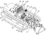
In figure 1, vehicle frame; 2, running gear; 21, crawler belt; 22, track adjusting wheel; 23, drive wheel; 3, power source system; 31, electrokinetic cell; 32, accessory feed; 33, accessory feed charger; 4, power drive system; 41, drive motor; 42, change speed gear box; 43, drive motor controller; 44, axle drive shaft; 5, electric lifting device; 51, lifting motor; 52, lifter; 53, lifting motor controller; 6, steering hardware; 61, steering arm; 62, brake pedal mechanism.
The specific embodiment
(embodiment 1)
See Fig. 1 and Fig. 2, the utlity model has vehicle frame 1, be positioned at the running gear 2 of vehicle frame 1 both sides, the power source system 3 that is positioned at vehicle frame 1 top and power drive system 4; Also comprise the electric lifting device 5 that is positioned at vehicle frame 1 one end, electric lifting device 5 is connected with power source system 3.Power drive system 4 comprises the drive motor 41 being connected with power source system 3, with drive motor 41 change speed gear box 42 being integrated by spline joint and the drive motor controller 43 that is positioned at power source system 3 tops; Drive motor 41 and change speed gear box 42 are fixedly installed on vehicle frame 1; Change speed gear box 42 both sides are provided with axle drive shaft 44, and rear end is provided with rear power output shaft.The drive motor 41 of front end, by mounting bracket, adopts two rubber mountings to be mounted by means of bolts on vehicle frame 1; The change speed gear box 42 of rear end is borrowed the adapter shaft at its lower hitch point place of group, adopts two drum type brake rubber mountings to be bolted on vehicle frame 1.Drive motor 41 directly by transmission of power to change speed gear box 42, a part is used for driving trac. to advance, a part is for the operation such as rotary tillage.
The utility model electric lifting device 5 comprises the lifting motor 51 that is positioned at vehicle frame 1 middle part, rear end, the lifter 52 being connected by adapter sleeve with lifting motor 51 and the lifting motor controller 53 that is positioned at drive motor 41 1 sides; Lifter 52 is fixed on change speed gear box 42 by bottom bolts, and lifting motor 51 is fixedly connected with lifter 52 by support.Lifting motor 51 rear portions are also provided with rear linkage, and rear linkage is connected with lifting motor 51.Lifting motor 51 directly by transmission of power to lifter 52, then drive that rear linkage and agricultural machinery and implement rise, down maneuver, to meet the requirement of different work operating mode.
The utility model power source system 3 comprises the electrokinetic cell 31 that is fixedly installed on vehicle frame 1 upper front end and the accessory feed 32 that is positioned at electrokinetic cell 31 tops, and accessory feed 32 sides are also provided with accessory feed charger 33; Drive motor controller 43 is positioned at electrokinetic cell 31 tops, and is fixedly installed between accessory feed 32 and drive motor 41.
The utility model is also provided with steering hardware 6, and steering hardware 6 comprises two steering arms 61 and coupled brake pedal mechanism 62; Two steering arms 61 are positioned at drive motor 41 both sides.When needs carry out steering operation, pull the steering arm 61 of this side, this side crawler belt 61 is implemented to braking, and opposite side crawler belt 61 normal operations turn to thereby realize.
The principle of work of this battery-powered tractor chassis power drive system: see Fig. 3, drive motor 41 is under drive motor controller 43 is controlled, and the working condition different according to trac., controls the rotating speed of drive motor 41.The electric energy conversion that drive motor 41 passes over electrokinetic cell 31 is mechanical energy, is then directly passed to change speed gear box 42, and change speed gear box 42 passes to respectively axle drive shaft 44 and rear power output shaft by power.The power that passes to axle drive shaft 44 drives the drive wheel 23 in running gear to rotate, and realizes the walking of trac.; The power that passes to rear power output shaft drives corresponding agricultural machinery and implement to carry out the work such as rotary tillage and sowing.The working condition different according to trac., lifting motor 51 is controlled its rotating speed by lifting motor controller 53, same lifting motor 51 is that mechanical energy passes to the lifter being directly connected with it by the electric energy conversion of electrokinetic cell 31, by lifter 52, is realized the ascending, descending of rear linkage (comprising agricultural machinery and implement) or is met certain tilling depth requirement.
Claims (10)
1. a battery-powered tractor chassis, comprises vehicle frame (1), is positioned at the running gear (2) of vehicle frame (1) both sides, the power source system (3) that is positioned at vehicle frame (1) top and power drive system (4); It is characterized in that: also comprise the electric lifting device (5) that is positioned at vehicle frame (1) one end, described electric lifting device (5) is connected with power source system (3).
2. battery-powered tractor according to claim 1 chassis, it is characterized in that: described power drive system (4) comprises the drive motor (41) being connected with power source system (3) change speed gear box (42) being integrated by spline joint with drive motor (41) and the drive motor controller (43) that is positioned at power source system (3) top; Described drive motor (41) and change speed gear box (42) are fixedly installed on vehicle frame (1); Described change speed gear box (42) both sides are provided with axle drive shaft (44), and rear end is provided with rear power output shaft.
3. battery-powered tractor according to claim 2 chassis, is characterized in that: the drive motor of described front end (41), by mounting bracket, adopts two rubber mountings to be mounted by means of bolts on vehicle frame (1); The change speed gear box of rear end (42) is borrowed the adapter shaft at its lower hitch point place of group, adopts two drum type brake rubber mountings to be bolted on vehicle frame (1).
4. battery-powered tractor according to claim 2 chassis, it is characterized in that: described electric lifting device (5) comprises the lifting motor (51) that is positioned at vehicle frame (1) rear end middle part the lifter (52) being connected by adapter sleeve with lifting motor (51) and be positioned at the lifting motor controller (53) of drive motor (41) one sides; It is upper that described lifter (52) is fixed on change speed gear box (42) by bottom bolts, and described lifting motor (51) is fixedly connected with lifter (52) by support.
5. battery-powered tractor according to claim 4 chassis, is characterized in that: described lifting motor (51) rear portion is also provided with rear linkage, and described rear linkage is connected with lifting motor (51).
6. according to the battery-powered tractor chassis described in claim 2 ~ 5 any one claim, it is characterized in that: described power source system (3) comprises the accessory feed (32) that is fixedly installed on the electrokinetic cell (31) of vehicle frame (1) upper front end and is positioned at electrokinetic cell (31) top, and described accessory feed (32) side is also provided with accessory feed charger (33); Described drive motor controller (43) is positioned at electrokinetic cell (31) top, and is fixedly installed between accessory feed (32) and drive motor (41).
7. according to the battery-powered tractor chassis described in claim 2 ~ 5 any one claim, it is characterized in that: described vehicle frame (1) comprises that described subframe is connected with running gear welding machine frame for subframe and the running gear frame of supporting motive force origin system (3) and power drive system (4).
8. battery-powered tractor according to claim 7 chassis, it is characterized in that: described running gear (2), for being positioned at the cterpillar drive of subframe both sides, comprises being positioned at two crawler belts (21) of vehicle frame (1) both sides and being positioned at the track adjusting wheel (22) of crawler belt (21) Inner Front End and the drive wheel (23) of rear end; Between described running gear frame bottom and crawler belt (21), be provided with a plurality of caterpillar wheels, running gear frame upper end and crawler belt are provided with carrier wheel and tightening device between (21); Described drive wheel (23) is fixedly connected with the axle drive shaft (43) on change speed gear box.
9. battery-powered tractor according to claim 8 chassis, is characterized in that: the caterpillar wheel on described every side crawler belt (21) has six.
10. according to the battery-powered tractor chassis described in claim 2 ~ 5 any one claim, it is characterized in that: also comprise steering hardware (6), described steering hardware (6) comprises two steering arms (61) and coupled brake pedal mechanism (62); Described two steering arms (61) are positioned at drive motor (41) both sides.
Priority Applications (1)
| Application Number | Priority Date | Filing Date | Title |
|---|---|---|---|
| CN201320587460.XU CN203450235U (en) | 2013-09-24 | 2013-09-24 | Electric tractor chassis |
Applications Claiming Priority (1)
| Application Number | Priority Date | Filing Date | Title |
|---|---|---|---|
| CN201320587460.XU CN203450235U (en) | 2013-09-24 | 2013-09-24 | Electric tractor chassis |
Publications (1)
| Publication Number | Publication Date |
|---|---|
| CN203450235U true CN203450235U (en) | 2014-02-26 |
Family
ID=50130134
Family Applications (1)
| Application Number | Title | Priority Date | Filing Date |
|---|---|---|---|
| CN201320587460.XU Expired - Fee Related CN203450235U (en) | 2013-09-24 | 2013-09-24 | Electric tractor chassis |
Country Status (1)
| Country | Link |
|---|---|
| CN (1) | CN203450235U (en) |
Cited By (3)
| Publication number | Priority date | Publication date | Assignee | Title |
|---|---|---|---|---|
| CN104029588A (en) * | 2014-06-19 | 2014-09-10 | 中国北方车辆研究所 | Integral mounting device for power transmission whole of electric vehicle |
| CN106070155A (en) * | 2016-07-30 | 2016-11-09 | 重庆科技学院 | Automatic target detection variable rate spray system based on PLC and control method thereof |
| CN115416501A (en) * | 2022-07-07 | 2022-12-02 | 青岛农业大学 | Small-horsepower range-increasing type electric tractor |
-
2013
- 2013-09-24 CN CN201320587460.XU patent/CN203450235U/en not_active Expired - Fee Related
Cited By (3)
| Publication number | Priority date | Publication date | Assignee | Title |
|---|---|---|---|---|
| CN104029588A (en) * | 2014-06-19 | 2014-09-10 | 中国北方车辆研究所 | Integral mounting device for power transmission whole of electric vehicle |
| CN106070155A (en) * | 2016-07-30 | 2016-11-09 | 重庆科技学院 | Automatic target detection variable rate spray system based on PLC and control method thereof |
| CN115416501A (en) * | 2022-07-07 | 2022-12-02 | 青岛农业大学 | Small-horsepower range-increasing type electric tractor |
Similar Documents
| Publication | Publication Date | Title |
|---|---|---|
| CN203450235U (en) | Electric tractor chassis | |
| CN201457505U (en) | Travelling device of tractor | |
| CN202827653U (en) | Power- assisted multipurpose wheelbarrow | |
| CN203618683U (en) | Full-automatic remotely controlled grain tedder | |
| CN215904628U (en) | Electric unmanned intelligent tractor | |
| CN201690743U (en) | Lawn sand-covering machine | |
| CN211809925U (en) | Remote control type pure electric orchard crawler micro-cultivator robot | |
| CN201774806U (en) | Chassis traveling device of multifunctional peanut and corn harvester | |
| CN205611192U (en) | Small -size environmental protection and energy saving miniwatt agricultural implement electric traction machine | |
| CN205454517U (en) | Electronic fertilizing and seeding device | |
| CN209806425U (en) | Self-propelled no-tillage machine seeder | |
| CN203157719U (en) | Power-driven four-wheel driving system | |
| CN204425931U (en) | Four-wheel farm land cultivator | |
| CN207644504U (en) | A kind of unmanned mini-tiller of solar energy | |
| CN204340830U (en) | A kind of novel farmland transport integrated multi-functional field machine device | |
| CN201800806U (en) | Crawler-type carrier vehicle capable of walking on rice ridges | |
| CN201830628U (en) | Orchard power chassis | |
| CN201928645U (en) | Towed mower | |
| CN107258131A (en) | Environmental-protection saves small-power farm implements electromotive electric traction machine | |
| CN210416786U (en) | Novel transport vechicle suitable for hills are planted type orchard closely | |
| CN203666399U (en) | Articulated steering four-wheel drive agricultural tractor | |
| CN202038383U (en) | Agricultural three-wheel drive tractor | |
| CN204762215U (en) | Cane cutting machine extensions type rear axle | |
| CN207000582U (en) | A kind of miniature hilly and mountainous land crawler tractor | |
| CN213566188U (en) | Electric tractor with adjustable gravity center |
Legal Events
| Date | Code | Title | Description |
|---|---|---|---|
| C14 | Grant of patent or utility model | ||
| GR01 | Patent grant | ||
| CF01 | Termination of patent right due to non-payment of annual fee | ||
| CF01 | Termination of patent right due to non-payment of annual fee |
Granted publication date: 20140226 Termination date: 20210924 |