CN203445173U - Storage battery gas vent structure capable of improving security property - Google Patents
Storage battery gas vent structure capable of improving security property Download PDFInfo
- Publication number
- CN203445173U CN203445173U CN201320423344.4U CN201320423344U CN203445173U CN 203445173 U CN203445173 U CN 203445173U CN 201320423344 U CN201320423344 U CN 201320423344U CN 203445173 U CN203445173 U CN 203445173U
- Authority
- CN
- China
- Prior art keywords
- storage battery
- gas vent
- vent structure
- steam vent
- battery
- Prior art date
- Legal status (The legal status is an assumption and is not a legal conclusion. Google has not performed a legal analysis and makes no representation as to the accuracy of the status listed.)
- Expired - Lifetime
Links
Images

Classifications
-
- Y—GENERAL TAGGING OF NEW TECHNOLOGICAL DEVELOPMENTS; GENERAL TAGGING OF CROSS-SECTIONAL TECHNOLOGIES SPANNING OVER SEVERAL SECTIONS OF THE IPC; TECHNICAL SUBJECTS COVERED BY FORMER USPC CROSS-REFERENCE ART COLLECTIONS [XRACs] AND DIGESTS
- Y02—TECHNOLOGIES OR APPLICATIONS FOR MITIGATION OR ADAPTATION AGAINST CLIMATE CHANGE
- Y02E—REDUCTION OF GREENHOUSE GAS [GHG] EMISSIONS, RELATED TO ENERGY GENERATION, TRANSMISSION OR DISTRIBUTION
- Y02E60/00—Enabling technologies; Technologies with a potential or indirect contribution to GHG emissions mitigation
- Y02E60/10—Energy storage using batteries
Landscapes
- Gas Exhaust Devices For Batteries (AREA)
Abstract
The utility model discloses a storage battery gas vent structure capable of improving security property. According to the technical scheme, the storage battery gas vent structure comprises a storage battery body and a storage battery cover, wherein a positive terminal and a negative terminal are arranged at one end of the storage battery cover. The storage battery gas vent structure is characterized in that a gas vent is formed in the storage battery cover; the gas vent is positioned in one end part of one side far away from the positive terminal and the negative terminal of the storage battery cover. According to the storage battery gas vent structure, the gas vent is formed far away from the terminals to the maximum extent, and as the gas vent is far away from the terminals, and the gas vent faces to the direction opposite to the directions of the terminals, the time that an explosive mixed gas is diffused to the terminal is long, the amount of the mixed gas diffused to the terminals is greatly reduced, and the effects of effectively avoiding corrosion to the terminals caused by acid mist and eliminating hidden danger of explosion to the maximum extent are achieved. The storage battery gas vent structure particularly has the benefits on a commercial vehicle large-capacity maintenance-free lead-acid storage battery that the positive terminal and the negative terminal are both positioned at the end in the length direction of the battery.
Description
Technical field
The utility model relates to a kind of battery technology, particularly can improve the storage battery vent structure of security performance, belongs to battery technology field.
Background technology
Maintenance-free lead accumulator in use can produce a kind of damp being mainly comprised of hydrogen and oxygen.For avoiding this mist, at inside battery, accumulate, cause inner pressure of battery to increase, destroy battery and even cause battery explosion, existing solution is on storage battery, to design exhaust passage and steam vent, makes the gas producing can pass through exhaust passage, finally by steam vent, discharges battery.At present maintenance-free lead accumulator steam vent layout has plenty of in plus end one side and negative terminal one side steam vent is set respectively, also has plenty of in plus end one side or negative terminal one side a steam vent is set.All there is following shortcoming in above-mentioned steam vent location layout: steam vent is nearer apart from terminal position, and in some cases, battery, when discharging hydrogen or oxygen gas, has acid mist and together discharges, and is easy to be diffused near terminal, causes the problems such as terminal corrosion; The 2nd, the damp of discharging is easily accumulated near terminal, has potential safety hazard.
Utility model content
The purpose of this utility model is the drawback for prior art, provides a kind of by rational deployment steam vent position, can improve the storage battery vent structure of security performance.
Problem described in the utility model realizes with following technical proposals:
A kind of storage battery vent structure that improves security performance, it comprises accumulator body and battery cap, one end on battery cap is provided with positive and negative terminal, and special feature is: described battery cap is provided with steam vent, and steam vent is positioned at the side end away from positive and negative terminal of battery cap.
The above-mentioned storage battery vent structure that improves security performance, described steam vent towards the direction that deviates from positive and negative terminal.
The above-mentioned storage battery vent structure that improves security performance, the number of described steam vent is 1-6.
The above-mentioned storage battery vent structure that improves security performance, in described accumulator body, be provided with several single lattice batteries, each single lattice battery top is provided with single grillages pore, and each single grillages pore is communicated with the public exhaust duct that is arranged on accumulator body top, and public exhaust duct is communicated with steam vent.
The utility model changes in use procedure for solving maintenance-free lead accumulator, the problem that the unsafe factor that hydrogen or oxygen gas causes terminal and the acid mist discharging with exhaust corrode terminal, steam vent layout to maintenance-free lead accumulator is improved: each steam vent is arranged on to battery cap away from one end of plus end and negative terminal, makes steam vent to greatest extent away from terminal.The mist that each single lattice of inside battery produce is discharged single lattice by single grillages air flue separately, then discharges outside storage battery through the public exhaust duct being communicated with each single grillages pore.Because steam vent is away from terminal, and steam vent is towards with terminal, opposite direction being set, explosive mist is diffused into terminal place and takes time longer, can significantly reduce the mist quantity that is diffused into terminal place, thereby realize, effectively avoid acid mist to cause terminal corrosion, eliminate to greatest extent the effect of hidden peril of explosion.This experiment is novel, and particularly for positive and negative terminal, to be all positioned at the commercial car of battery length direction one end the most obvious by large capacity maintenance-free lead accumulator benefit.
Accompanying drawing explanation
Below in conjunction with accompanying drawing, the utility model is described in further detail.
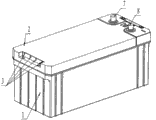
Fig. 1 is the utility model structural representation;
Fig. 2 is that the utility model is used view.
In figure, each list of reference numerals is: 1, accumulator body, 2, battery cap, 3, steam vent, 4, single lattice battery, 5, single grillages pore, 6, public exhaust duct, 7, plus end, 8, negative terminal.
Embodiment
Referring to Fig. 1, Fig. 2, the utility model comprises accumulator body 1 and is encapsulated in the battery cap 2 on accumulator body, and the one end on battery cap is arranged side by side plus end 7 and negative terminal 8, and the other end on battery cap arranges steam vent 3.Maintenance-free lead accumulator is in normal use procedure, can produce that to take hydrogen and oxygen be main mixed explosion mist, under the effect of the factor such as battery inner and outer air pressure is poor, this gas will inevitably be discharged by steam vent, this gas is met naked light and can be blasted, this gas may be mixed with and have corrosive acid mist simultaneously, so steam vent location layout is very important.The steam vent layout thinking the utility model proposes is, as far as possible away from terminal, and steam vent 3 towards the direction that deviates from positive and negative terminal, can avoid like this acid mist to cause terminal corrosion, eliminate to greatest extent hidden peril of explosion.The number of described steam vent is 1-6.
Referring to Fig. 1, in accumulator body 1, be provided with normally six single lattice of several single lattice battery 4(), each single lattice battery top is provided with single grillages pore 5, and each single grillages pore is communicated with the public exhaust duct 6 that is arranged on accumulator body top, and public exhaust duct is communicated with steam vent 3.Like this, the gas producing in each single lattice enters public exhaust duct through single grillages pore, then by public exhaust duct, enters steam vent and discharge.
Claims (4)
1. the storage battery vent structure that can improve security performance, it comprises accumulator body (1) and battery cap (2), one end on battery cap is provided with positive and negative terminal, it is characterized in that: described battery cap (2) is provided with steam vent (3), steam vent is positioned at the side end away from positive and negative terminal of battery cap.
2. the storage battery vent structure that improves security performance according to claim 1, is characterized in that, described steam vent (3) towards the direction that deviates from positive and negative terminal.
3. the storage battery vent structure that improves security performance according to claim 2, is characterized in that, the number of described steam vent (3) is 1-6.
4. according to the storage battery vent structure of the improved security performance described in claim 1 or 2 or 3, it is characterized in that, in described accumulator body (1), be provided with several single lattice batteries (4), each single lattice battery top is provided with single grillages pore (5), each single grillages pore is communicated with the public exhaust duct (6) that is arranged on accumulator body top, and public exhaust duct is communicated with steam vent (3).
Priority Applications (1)
| Application Number | Priority Date | Filing Date | Title |
|---|---|---|---|
| CN201320423344.4U CN203445173U (en) | 2013-07-17 | 2013-07-17 | Storage battery gas vent structure capable of improving security property |
Applications Claiming Priority (1)
| Application Number | Priority Date | Filing Date | Title |
|---|---|---|---|
| CN201320423344.4U CN203445173U (en) | 2013-07-17 | 2013-07-17 | Storage battery gas vent structure capable of improving security property |
Publications (1)
| Publication Number | Publication Date |
|---|---|
| CN203445173U true CN203445173U (en) | 2014-02-19 |
Family
ID=50096196
Family Applications (1)
| Application Number | Title | Priority Date | Filing Date |
|---|---|---|---|
| CN201320423344.4U Expired - Lifetime CN203445173U (en) | 2013-07-17 | 2013-07-17 | Storage battery gas vent structure capable of improving security property |
Country Status (1)
| Country | Link |
|---|---|
| CN (1) | CN203445173U (en) |
Cited By (1)
| Publication number | Priority date | Publication date | Assignee | Title |
|---|---|---|---|---|
| CN114243201A (en) * | 2021-12-20 | 2022-03-25 | 风帆(扬州)有限责任公司 | High valve accuse non-maintaining battery of security |
-
2013
- 2013-07-17 CN CN201320423344.4U patent/CN203445173U/en not_active Expired - Lifetime
Cited By (2)
| Publication number | Priority date | Publication date | Assignee | Title |
|---|---|---|---|---|
| CN114243201A (en) * | 2021-12-20 | 2022-03-25 | 风帆(扬州)有限责任公司 | High valve accuse non-maintaining battery of security |
| CN114243201B (en) * | 2021-12-20 | 2023-11-17 | 风帆(扬州)有限责任公司 | High valve accuse maintenance-free battery of security |
Similar Documents
| Publication | Publication Date | Title |
|---|---|---|
| CN203445173U (en) | Storage battery gas vent structure capable of improving security property | |
| CN202497628U (en) | Electric vehicle | |
| CN202495544U (en) | Power battery | |
| CN107240662A (en) | A kind of battery modules shell of high safety performance | |
| CN201845818U (en) | Assembly module of grid type power batteries | |
| CN206282915U (en) | A kind of outer penetration type side exhaust battery explosion-proof cap | |
| CN203192873U (en) | Lithium battery explosion-proof cap | |
| CN201663054U (en) | One-way exhaust valve of super capacitor | |
| CN211125764U (en) | Electric locomotive lithium battery structure with double-sealing structure | |
| CN202888340U (en) | Storage battery of combined type gas filter piece exhaust system | |
| CN209282282U (en) | A kind of power battery explosion protection valve and power battery | |
| CN202772212U (en) | Explosion-proof storage battery | |
| CN203108032U (en) | Aerosol fire extinguishing device | |
| CN202948990U (en) | Storage battery with air chamber exhausting system | |
| CN201430170Y (en) | Tank structure of modified ferric phosphate lithium battery | |
| CN204668375U (en) | A kind of flange-cooled power accumulator case | |
| CN201536124U (en) | Special fixture for aluminum shell lithium ion battery cell bended electrode lug | |
| CN204011491U (en) | A kind of miniature cylinder lithium ion battery | |
| CN205303568U (en) | Safe explosion -proof battery module | |
| CN203826459U (en) | Novel explosion-proof structure of power lithium ion battery | |
| CN205303593U (en) | Lithium cell structure for motorcycle | |
| CN207149595U (en) | A kind of multifunctional motor-driven vehicle electric pool device | |
| CN203617354U (en) | High-power battery used for lighting | |
| CN204130619U (en) | In a kind of novel lead-acid storage battery, large density battery changes into terminal protective cover | |
| CN101924193A (en) | Tank structure of lithium iron phosphate battery |
Legal Events
| Date | Code | Title | Description |
|---|---|---|---|
| C14 | Grant of patent or utility model | ||
| GR01 | Patent grant | ||
| C41 | Transfer of patent application or patent right or utility model | ||
| TR01 | Transfer of patent right |
Effective date of registration: 20160714 Address after: 071057 Hebei province Baoding Fuchang Road No. 8 Patentee after: FENGFAN Co.,Ltd. Address before: 071057 Hebei province Baoding Fuchang Road No. 8 Patentee before: FENGFAN Co.,Ltd. |
|
| CX01 | Expiry of patent term | ||
| CX01 | Expiry of patent term |
Granted publication date: 20140219 |