CN203426279U - Continuous stamping die for manufacturing backboard communication connector terminal - Google Patents
Continuous stamping die for manufacturing backboard communication connector terminal Download PDFInfo
- Publication number
- CN203426279U CN203426279U CN201320518457.2U CN201320518457U CN203426279U CN 203426279 U CN203426279 U CN 203426279U CN 201320518457 U CN201320518457 U CN 201320518457U CN 203426279 U CN203426279 U CN 203426279U
- Authority
- CN
- China
- Prior art keywords
- punch
- die
- flake
- contact zone
- lower bolster
- Prior art date
- Legal status (The legal status is an assumption and is not a legal conclusion. Google has not performed a legal analysis and makes no representation as to the accuracy of the status listed.)
- Expired - Fee Related
Links
Images
Landscapes
- Manufacturing Of Electrical Connectors (AREA)
Abstract
The utility model relates to a continuous stamping die for manufacturing a backboard communication connector terminal. A stamping lead hole male die, a trimming round hole stamping male die, a product pre-cutting male die, a product fisheye and contact zone small elastic sheet thinning male die, a contact zone small elastic sheet smoothing male die, a fisheye appearance puncturing male die, a fisheye appearance blanking male die, a fisheye beveling male die, a fisheye smoothing male die, a fisheye blanking male die, a product appearance blanking and contact zone large elastic sheet bending male die, a product appearance blanking male die, a contact zone large elastic sheet bending male die, a contact zone large elastic sheet bending adjustment male die, a fisheye adjustment male die and a flatness adjustment male die are sequentially arranged on an upper clamping plate of the die, and female dies of all the male dies are sequentially arranged at the corresponding positions of a lower die plate. Through the action of the male dies and the female dies, the backboard communication connector terminal can be manufactured on one die, continuous production of the backboard communication connector terminal can be achieved, the working procedure is simple, production cost is low, production cycle is short, and production efficiency is greatly improved.
Description
Technical field
The utility model relates to a kind of continuous stamping die, relates in particular to a kind of continuous stamping die of manufacturing back panel connector terminal.
Background technology
In prior art, for the manufacture of backboard communications connectors terminal, need a plurality of work steps to complete, for example circular hole punching press, the shell fragment profile blanking of product contact zone, the shell fragment bending of product contact zone, product thins pressure-sizing processing, " flake " blanking, the steps such as " flake " chamfering.In these a plurality of punching courses, need a plurality of single dies to realize, wasted the cost that manufacturing enterprise a large amount of human resources, technique process are loaded down with trivial details, increase Mold Making and maintenance simultaneously, cannot realize production in enormous quantities fast.Cause the integral production cost of enterprise high, extended production cycle of product, reduced enterprise efficiency.
Utility model content
In order to overcome, adopt that prior art manufactures that backboard communications connectors terminal technique process is loaded down with trivial details, Mold Making and maintenance cost high, cannot realize quick production in enormous quantities, the defect that production efficiency is low, the utility model aims to provide a kind of continuous stamping die of manufacturing backboard communications connectors terminal, this continuous stamping die prodigiosin is realized each operation that backboard communications connectors terminal is manufactured, do not need a plurality of operation moulds, having realized backboard communications connectors terminal produces continuously, technique process is simple, production cost is low, with short production cycle and greatly improved production efficiency.
In order to solve the problems of the technologies described above, the technical solution adopted in the utility model is:
A continuous stamping die of manufacturing backboard communications connectors terminal, is characterized in that: comprise upper bolster, upper padding plate, train wheel bridge, baffle plate, stripper plate, stock guide, lower bolster, lower bolster and die shoe, described upper padding plate is fixed on train wheel bridge, described train wheel bridge is fixed on upper bolster together with upper padding plate, baffle plate is fixed on stripper plate, described lower bolster is fixed on lower bolster, described lower bolster is fixed on die shoe together with lower bolster, according to material strip traffic direction, is disposed with and rushes bullport punch on described train wheel bridge, trimming circular hole punching press punch, product is cut punch in advance, the little shell fragment in product flake and contact zone thins punch, contact zone submissile sheet rounding punch, flake profile punctures punch, flake profile blanking punch, flake bevelling punch, flake rounding punch, flake blanking punch, primary production profile blanking punch, contact zone submissile sheet bending punch, afterproduct profile blanking punch, the large shell fragment bending in contact zone punch, punch is adjusted in the large shell fragment bending in contact zone, flake adjusts punch and flatness is adjusted punch, and the guide elements stripper plate that is disposed with each punch on the relevant position of described stripper plate enters son, is disposed with the die of each punch on the relevant position of described lower bolster.
Each guide elements stripper plate on described stripper plate enters son place and is provided with alignment pin.
On described upper bolster, be provided with outer bush, on described die shoe, be provided with outer guiding post, described upper bolster and die shoe coordinate by described outer bush and outer guiding post positioning and guiding.
On described train wheel bridge, be provided with inner guiding post and interior guide pin bushing, be provided with guide pin bushing in counterdie on described lower bolster, described train wheel bridge and lower bolster are by guide pin bushing and inner guiding post positioning and guiding interference fit in described interior guide pin bushing, counterdie.
The described bullport punch that rushes, trimming circular hole punching press punch, product is cut punch in advance, the little shell fragment in product flake and contact zone thins punch, contact zone submissile sheet rounding punch, flake profile punctures punch, flake profile blanking punch, flake bevelling punch, flake rounding punch, flake blanking punch, primary production profile blanking punch, contact zone submissile sheet bending punch, afterproduct profile blanking punch, the large shell fragment bending in contact zone punch, punch is adjusted in the large shell fragment bending in contact zone, flake adjusts punch and flatness adjustment punch is all fastened on train wheel bridge by pressing plate mode.
Described train wheel bridge uses the stay bolt through upper padding plate to be locked on upper bolster, and train wheel bridge and die holder adopt the location of having strong market potential.
Described lower bolster uses the stay bolt through lower bolster to be locked on die shoe, and lower bolster and die holder adopt the location of having strong market potential.
On described lower bolster, be provided with stock guide, stock guide is arranged on lower bolster by screw.
On described lower bolster, be provided with buoyant pin.
The utlity model has following advantage:
1, the utility model rushes bullport punch by setting gradually on train wheel bridge, trimming circular hole punching press punch, product is cut punch in advance, the little shell fragment in product flake and contact zone thins punch, contact zone submissile sheet rounding punch, flake profile punctures punch, flake profile blanking punch, the flake angle of falling C punch, the flake angle of falling R punch, flake blanking punch, product design blanking punch, contact zone submissile sheet bending punch, product design blanking punch, the large shell fragment bending in contact zone punch, punch is adjusted in the large shell fragment bending in contact zone, flake adjusts punch and flatness is adjusted punch, the guide elements stripper plate that is disposed with each punch on the relevant position of stripper plate enters son, on the relevant position of lower bolster, be disposed with the die of each punch, the effect by each punch and die realizes successively backboard communications connectors terminal and rushes bullport work step, trimming circular hole punching press work step, the pre-cut step of product, the little shell fragment of product " flake " and contact zone thins work step, contact zone submissile sheet rounding work step, " flake " profile punctures work step, flake profile blanking work step, flake bevelling and flake rounding work step, fish eyelet blanking work step, product design blanking work step, contact zone submissile sheet bending work step, the large shell fragment bending in contact zone work step, work step is adjusted in the large shell fragment bending in contact zone, flake is adjusted work step, flatness is adjusted work step.Through these work steps, just can produce backboard communications connectors terminal, backboard communications connectors terminal is just plastic on a mould, do not need a plurality of single die tools, operation is simple, easy operating, it has been realized backboard communications connectors terminal and has produced continuously, technique process is simple, and production cost is low, with short production cycle and greatly improved production efficiency.
2, each the guide elements stripper plate on the utility model stripper plate enters son place and is provided with alignment pin, and each is decided to be pin and coordinates with the locating hole on material strip the precise positioning that can realize material strip, assurance product Working position accurate, and error is little.
3, on the utility model upper bolster, be provided with outer bush, on described die shoe, be provided with outer guiding post, described upper bolster and die shoe coordinate by described outer bush and outer guiding post positioning and guiding, on described train wheel bridge, be provided with interior guide pin bushing, on described lower bolster, be provided with inner guiding post, described train wheel bridge and lower bolster are by described interior guide pin bushing and inner guiding post positioning and guiding interference fit.By coordinating of interior outer guiding post and guide pin bushing, precise positioning and guiding when realizing mould and moving up and down, avoid punch and die to misplace when moving up and down.
4, the utility model rushes bullport punch, trimming circular hole punching press punch, product is cut punch in advance, the little shell fragment in product flake and contact zone thins punch, contact zone submissile sheet rounding punch, flake profile punctures punch, flake profile blanking punch, flake bevelling punch, flake rounding punch, flake blanking punch, product design blanking, contact zone submissile sheet bending punch, product design blanking punch, the large shell fragment bending in contact zone punch, punch is adjusted in the large shell fragment bending in contact zone, flake adjusts punch and flatness adjustment punch is all fastened on train wheel bridge by pressing plate mode.When punch wearing and tearing or damage, be convenient to change punch.
5, the utility model train wheel bridge uses the stay bolt through upper padding plate to be locked on upper bolster, train wheel bridge and die holder adopt the location of having strong market potential, interaction energy by stay bolt is fixed together train wheel bridge, upper padding plate and upper bolster firmly, has strong market potential for preventing displacement mutually between them.
6, the utility model lower bolster uses the stay bolt through lower bolster to be locked on die shoe, and lower bolster and die holder adopt the location of having strong market potential.Interaction energy by stay bolt is fixed together lower bolster, lower bolster and die shoe firmly, has strong market potential for preventing displacement mutually between them.
7, on the utility model lower bolster, be provided with stock guide, stock guide is arranged on lower bolster by screw, and stock guide is for material strip location and material strip is departed to stripper plate surface, and counterdie die is pressed in template, there will not be die to jump out problem.
8, on the utility model lower bolster, be provided with buoyant pin, buoyant pin is for buoyance lift material strip, material strip departed to lower bolster surface and be convenient to material strip and transmit to subsequent processing.
Accompanying drawing explanation
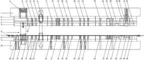
Fig. 1 is the utility model overall structure schematic diagram.
In figure, mark 1, upper bolster, 2, upper padding plate, 3, train wheel bridge, 4, baffle plate, 5, stripper plate, 6, batch turning plate, 7, material strip, 8, lower bolster, 9, lower bolster, 10, die shoe, 11, outer bush, 12, rush bullport punch, 13, trimming circular hole punching press punch, 14, product is cut punch, 15 in advance, inner guiding post, 16, interior guide pin bushing, 17, the little shell fragment in product flake and contact zone thins punch, 18, contact zone submissile sheet rounding punch, 19, flake profile punctures punch, 20, flake profile blanking punch, 21, flake bevelling punch, 22, a flake rounding punch, 23, secondary flake rounding punch, 24, fish eyelet blanking punch, 25, primary production profile blanking punch, 26, contact zone submissile sheet bending punch, 27, afterproduct profile blanking punch, 28, the large shell fragment bending in a contact zone punch, 29, the large shell fragment bending in secondary contact zone punch, 30, punch, 31 are adjusted in the large shell fragment bending in contact zone, flake is adjusted punch, 32, flatness is adjusted punch, 33, screw, 34, buoyant pin, 35, outer guiding post, 36, rush bullport die, 37, trimming circular hole stamping cavity die, 38, product is cut die, 39 in advance, guide pin bushing in counterdie, 40, the little shell fragment in product flake and contact zone thins die, 41, contact zone submissile sheet rounding die, 42, flake profile punctures die, and 43, flake profile blanking die, 44, flake bevelling die, 45, a flake rounding die, 46, secondary flake rounding die, 47, fish eyelet blanking die, 48, primary production profile blanking die, 49, contact zone submissile sheet bending female die, 50, afterproduct profile blanking die, 51, a large shell fragment bending female die in contact zone, 52, the large shell fragment bending female die in secondary contact zone, 53, die, 54 are adjusted in the large shell fragment bending in contact zone, flake is adjusted die, 55, flatness is adjusted die, 56, alignment pin.
The specific embodiment
As shown in Figure 1, the utility model comprises: upper bolster 1, upper padding plate 2, train wheel bridge 3, baffle plate 4, stripper plate 5, stock guide 6, lower bolster 8, lower bolster 9 and die shoe 10.Their assembling mode: upper padding plate 2 is fixed on upper bolster 1, train wheel bridge 3 use are locked on upper bolster 1 through the stay bolt of upper padding plate 2, train wheel bridge 3 adopts with die holder 1 location of having strong market potential, baffle plate 4 is fixed on stripper plate 5, lower bolster 9 is fixed on die shoe 10, lower bolster 8 use are locked on die shoe 10 through the stay bolt of lower bolster 9, and lower bolster 8 adopts with die holder 10 location of having strong market potential.Upper and lower mould is by being fastened on the outer bush 11 of upper bolster 10 and being fastened on the outer guiding post 35 interference fit positioning and guidings on die shoe 10, train wheel bridge 3 and stripper plate 5 and lower bolster 8 are by being arranged on inner guiding post 15 on stripper plate 5 and the interior guide pin bushing 16 on train wheel bridge 3, guide pin bushing 39 in counterdie on lower bolster 8, interference fit correcting, material strip 7 keeps location accurately by the alignment pin 56 being arranged on stripper plate 5 with mould, lower bolster 8 is designed with buoyant pin 34 for buoyance lift material strip 7, material strip is convenient to in material strip 7 disengaging lower bolster 8 surfaces and to subsequent processing, transmits.Lower bolster 8 is designed with stock guide 6, and stock guide 6 is fixed by screws on lower bolster 8, locates and material strip is departed to stripper plate surface, and lower bolster 8 dies are pressed in lower bolster 8 for material strip 7, there will not be die to jump out problem.
Produce backboard communications connectors terminal punching die all process steps structure and have 25, upper and lower mould counter structure comprises and rushes bullport work step, trimming circular hole punching press work step, the pre-cut step of product, the little shell fragment in product flake and contact zone thins work step, contact zone submissile sheet rounding work step, flake profile punctures work step, flake profile blanking work step, flake bevelling and flake rounding work step, fish eyelet blanking work step, product design blanking work step, contact zone submissile sheet bending work step, the large shell fragment bending in contact zone work step, work step is adjusted in the large shell fragment bending in contact zone, flake is adjusted work step, flatness is adjusted work step etc.
On train wheel bridge 3, from feed end, start to be disposed with the punch of all process steps of producing backboard communications connectors terminal, punch is fastened on train wheel bridge 3 by pressing plate mode.Comprise: rush bullport punch 12, trimming circular hole punching press punch 13, product is cut punch 14 in advance, the little shell fragment in product flake and contact zone thins punch 17, contact zone submissile sheet rounding punch 18, flake profile punctures punch 19, flake profile blanking punch 20, flake bevelling punch 21, flake rounding punch (it is divided into flake rounding punch 22 and secondary flake rounding punch 23), fish eyelet blanking punch 24, primary production profile blanking punch 25, contact zone submissile sheet bending punch 26, afterproduct profile blanking punch 27, the large shell fragment bending in contact zone punch (it is divided into the large shell fragment bending in contact zone punch 28 and the large shell fragment bending in secondary contact zone punch 29), punch 30 is adjusted in the large shell fragment bending in contact zone, flake is adjusted punch 31, flatness is adjusted punch 32 etc.
The de-material version of punch guide elements that starts to be disposed with from feed end all process steps of producing backboard communications connectors terminal on stripper plate 5 enters son.On stripper plate 5, each work step is provided with the alignment pin 56 for material strip 7 guide-localizations, coordinates with material strip 7 locating holes, guarantees product space precision.
On lower bolster 8, from feed end, start to be disposed with the die of all process steps of producing backboard communications connectors terminal, comprise: rush bullport die 36, trimming circular hole stamping cavity die 37, product is cut die 38 in advance, the little shell fragment in product flake and contact zone thins work die 40, contact zone submissile sheet rounding die 41, flake profile punctures die 42, flake profile blanking die 43, flake bevelling die 44, a flake rounding die 45, secondary flake rounding die 46, fish eyelet blanking die 47, primary production profile blanking die 48, contact zone submissile sheet bending female die 49, afterproduct profile blanking die 50, a large shell fragment bending female die 51 in contact zone, the large shell fragment bending female die 52 in secondary contact zone, die 53 is adjusted in the large shell fragment bending in contact zone, flake is adjusted die 54, flatness is adjusted die 55 etc., die is corresponding one by one with the punch on train wheel bridge.
Operation principle of the present utility model is as follows:
Raw material are positioned on feeding disk, and material strip, through stamping machine feed mechanism, enters mould accurately.This stamping die is arranged on 60T press machine tool platform, top shoe by forcing press drives upper mould to move up and down stamped workpieces, once, each station completes an operation in every punching press, comes last station and produces a part, then material strip 7 is along the advance distance of a unit of arrow shown in figure, carry out punching press, product, to mould discharging, is realized continuous rewinding through automatically responding to rewinding frame again, form and produce continuously production line, realize accurate, efficient, batch production.
Claims (9)
1. a continuous stamping die of manufacturing backboard communications connectors terminal, is characterized in that: comprise upper bolster, upper padding plate, train wheel bridge, baffle plate, stripper plate, stock guide, lower bolster, lower bolster and die shoe, described upper padding plate is fixed on train wheel bridge, described train wheel bridge is fixed on upper bolster together with upper padding plate, baffle plate is fixed on stripper plate, described lower bolster is fixed on lower bolster, described lower bolster is fixed on die shoe together with lower bolster, according to material strip traffic direction, is disposed with and rushes bullport punch on described train wheel bridge, trimming circular hole punching press punch, product is cut punch in advance, the little shell fragment in product flake and contact zone thins punch, contact zone submissile sheet rounding punch, flake profile punctures punch, flake profile blanking punch, flake bevelling punch, flake rounding punch, flake blanking punch, primary production profile blanking punch, contact zone submissile sheet bending punch, afterproduct profile blanking punch, the large shell fragment bending in contact zone punch, punch is adjusted in the large shell fragment bending in contact zone, flake adjusts punch and flatness is adjusted punch, and the guide elements stripper plate that is disposed with each punch on the relevant position of described stripper plate enters son, is disposed with the die of each punch on the relevant position of described lower bolster.
2. a kind of continuous stamping die of manufacturing backboard communications connectors terminal according to claim 1, is characterized in that: each the guide elements stripper plate on described stripper plate enters son place and is provided with alignment pin.
3. a kind of continuous stamping die of manufacturing backboard communications connectors terminal according to claim 1 and 2, it is characterized in that: on described upper bolster, be provided with outer bush, on described die shoe, be provided with outer guiding post, described upper bolster and die shoe coordinate by described outer bush and outer guiding post positioning and guiding.
4. a kind of continuous stamping die of manufacturing backboard communications connectors terminal according to claim 1, it is characterized in that: on described train wheel bridge, be provided with interior guide pin bushing and inner guiding post, on described lower bolster, be provided with guide pin bushing in counterdie, described train wheel bridge and lower bolster are by guide pin bushing and inner guiding post positioning and guiding interference fit in described interior guide pin bushing, counterdie.
5. a kind of continuous stamping die of manufacturing backboard communications connectors terminal according to claim 1, it is characterized in that: the described bullport punch that rushes, trimming circular hole punching press punch, product is cut punch in advance, the little shell fragment in product flake and contact zone thins punch, contact zone submissile sheet rounding punch, flake profile punctures punch, flake profile blanking punch, flake bevelling punch, flake rounding punch, flake blanking punch, primary production profile blanking punch, contact zone submissile sheet bending punch, afterproduct profile blanking punch, the large shell fragment bending in contact zone punch, punch is adjusted in the large shell fragment bending in contact zone, flake adjusts punch and flatness adjustment punch is all fastened on train wheel bridge by pressing plate mode.
6. a kind of continuous stamping die of manufacturing backboard communications connectors terminal according to claim 1, is characterized in that: described train wheel bridge uses the stay bolt through upper padding plate to be locked on upper bolster, and train wheel bridge and die holder adopt the location of having strong market potential.
7. according to a kind of continuous stamping die of manufacturing backboard communications connectors terminal described in claim 1 or 6, it is characterized in that: described lower bolster uses the stay bolt through lower bolster to be locked on die shoe, lower bolster and die holder adopt the location of having strong market potential.
8. a kind of continuous stamping die of manufacturing backboard communications connectors terminal according to claim 1, is characterized in that: on described lower bolster, be provided with stock guide, stock guide is arranged on lower bolster by screw.
9. according to a kind of continuous stamping die of manufacturing backboard communications connectors terminal described in claim 1 or 8, it is characterized in that: on described lower bolster, be provided with buoyant pin.
Priority Applications (1)
| Application Number | Priority Date | Filing Date | Title |
|---|---|---|---|
| CN201320518457.2U CN203426279U (en) | 2013-08-23 | 2013-08-23 | Continuous stamping die for manufacturing backboard communication connector terminal |
Applications Claiming Priority (1)
| Application Number | Priority Date | Filing Date | Title |
|---|---|---|---|
| CN201320518457.2U CN203426279U (en) | 2013-08-23 | 2013-08-23 | Continuous stamping die for manufacturing backboard communication connector terminal |
Publications (1)
| Publication Number | Publication Date |
|---|---|
| CN203426279U true CN203426279U (en) | 2014-02-12 |
Family
ID=50055341
Family Applications (1)
| Application Number | Title | Priority Date | Filing Date |
|---|---|---|---|
| CN201320518457.2U Expired - Fee Related CN203426279U (en) | 2013-08-23 | 2013-08-23 | Continuous stamping die for manufacturing backboard communication connector terminal |
Country Status (1)
| Country | Link |
|---|---|
| CN (1) | CN203426279U (en) |
Cited By (8)
| Publication number | Priority date | Publication date | Assignee | Title |
|---|---|---|---|---|
| CN104384352A (en) * | 2014-11-04 | 2015-03-04 | 四川瑞宝电子有限责任公司 | Continuous stamping die for manufacturing antenna terminal of wearable equipment |
| CN104438833A (en) * | 2014-11-04 | 2015-03-25 | 四川瑞宝电子有限责任公司 | Continuous stamping die for manufacturing threading device communication connector terminal |
| CN105458117A (en) * | 2015-11-10 | 2016-04-06 | 绵阳永创精密机械有限公司 | Plunger hole rounding process for automobile engine |
| CN109692909A (en) * | 2019-01-14 | 2019-04-30 | 上海徕木电子股份有限公司 | A kind of preparation process of connector fish forked terminal |
| CN109807233A (en) * | 2019-03-13 | 2019-05-28 | 林张瑜 | A kind of rib cutting apparatus for bending of connecting terminal metal clips |
| CN109807234A (en) * | 2019-03-13 | 2019-05-28 | 林张瑜 | A kind of production method of connecting terminal metal clips and the rib cutting bending equipment of metal clips |
| CN111906192A (en) * | 2020-06-30 | 2020-11-10 | 奕东电子(常熟)有限公司 | High-precision stamping mechanism for high-density small-space multi-PIN fisheye terminal |
| CN113560427A (en) * | 2021-09-26 | 2021-10-29 | 苏州铭峰精密机械有限公司 | Continuous forming method for fine terminals |
-
2013
- 2013-08-23 CN CN201320518457.2U patent/CN203426279U/en not_active Expired - Fee Related
Cited By (13)
| Publication number | Priority date | Publication date | Assignee | Title |
|---|---|---|---|---|
| CN104438833A (en) * | 2014-11-04 | 2015-03-25 | 四川瑞宝电子有限责任公司 | Continuous stamping die for manufacturing threading device communication connector terminal |
| CN104438833B (en) * | 2014-11-04 | 2016-04-27 | 四川瑞宝电子有限责任公司 | A kind of continuous stamping die manufacturing threading device talk bonder terminal |
| CN104384352B (en) * | 2014-11-04 | 2016-06-15 | 四川瑞宝电子有限责任公司 | A kind of manufacture can the continuous stamping die of threading device antenna terminal |
| CN104384352A (en) * | 2014-11-04 | 2015-03-04 | 四川瑞宝电子有限责任公司 | Continuous stamping die for manufacturing antenna terminal of wearable equipment |
| CN105458117A (en) * | 2015-11-10 | 2016-04-06 | 绵阳永创精密机械有限公司 | Plunger hole rounding process for automobile engine |
| CN109692909B (en) * | 2019-01-14 | 2023-12-15 | 上海徕木电子股份有限公司 | Preparation process of fish fork terminal for connector |
| CN109692909A (en) * | 2019-01-14 | 2019-04-30 | 上海徕木电子股份有限公司 | A kind of preparation process of connector fish forked terminal |
| CN109807233A (en) * | 2019-03-13 | 2019-05-28 | 林张瑜 | A kind of rib cutting apparatus for bending of connecting terminal metal clips |
| CN109807233B (en) * | 2019-03-13 | 2020-04-17 | 锐青科技(重庆)有限公司 | Rib cutting and bending device of metal elastic sheet for wiring terminal |
| CN109807234A (en) * | 2019-03-13 | 2019-05-28 | 林张瑜 | A kind of production method of connecting terminal metal clips and the rib cutting bending equipment of metal clips |
| CN111906192A (en) * | 2020-06-30 | 2020-11-10 | 奕东电子(常熟)有限公司 | High-precision stamping mechanism for high-density small-space multi-PIN fisheye terminal |
| CN113560427A (en) * | 2021-09-26 | 2021-10-29 | 苏州铭峰精密机械有限公司 | Continuous forming method for fine terminals |
| CN113560427B (en) * | 2021-09-26 | 2022-01-07 | 苏州铭峰精密机械有限公司 | Continuous forming method for fine terminals |
Similar Documents
| Publication | Publication Date | Title |
|---|---|---|
| CN203426279U (en) | Continuous stamping die for manufacturing backboard communication connector terminal | |
| CN203426282U (en) | Continuous stamping die for manufacturing elastic sheet of drilling equipment | |
| CN203426280U (en) | Continuous stamping die for manufacturing connector terminal | |
| CN203426263U (en) | Continuous stamping die used for producing tablet computer outer shell structural parts | |
| CN205414112U (en) | Continuous stamping die of production shell fragment terminal | |
| CN102610978B (en) | Method and device for machining motor carbon brush carrier | |
| CN206882527U (en) | A kind of diel of Multiple Shape piece | |
| CN204262173U (en) | A kind of continuous stamping die manufacturing automobile fog light movable contact spring | |
| CN206882509U (en) | A kind of diel of piece terminal | |
| CN104438833B (en) | A kind of continuous stamping die manufacturing threading device talk bonder terminal | |
| CN104384352A (en) | Continuous stamping die for manufacturing antenna terminal of wearable equipment | |
| CN205414148U (en) | Make continuous stamping die of high -speed transmission backplate communication connector terminal | |
| CN103817262A (en) | Four-leakage hinge crimping device | |
| CN203470650U (en) | Punching and bending progressive die | |
| CN204262172U (en) | A kind of continuous stamping die manufacturing automobile movable contact spring | |
| CN206263034U (en) | A kind of lug bending shaping mechanism | |
| CN204234579U (en) | A kind of continuous stamping die of manufacturing intelligence threading device structure part | |
| CN203725654U (en) | Four-linkage hinge circle rolling equipment | |
| CN205183497U (en) | Make continuous stamping die of board to board connector terminal | |
| CN205414152U (en) | Continuous stamping die of production high speed communication signal transmission terminal | |
| CN203459527U (en) | Bending mold for manufacturing U-shaped workpiece | |
| CN203370925U (en) | Continuous die product chamfer device | |
| CN206632212U (en) | A kind of continuous mould for processing micro-wave oven top casing | |
| CN205414161U (en) | Continuous stamping die of production electrical apparatus class spring leaf | |
| CN205032569U (en) | Make continuous stamping die of backplate communication connector shielding piece |
Legal Events
| Date | Code | Title | Description |
|---|---|---|---|
| C14 | Grant of patent or utility model | ||
| GR01 | Patent grant | ||
| CP01 | Change in the name or title of a patent holder | ||
| CP01 | Change in the name or title of a patent holder |
Address after: 629000 Suining Economic Development Zone, Sichuan Road, ERON Microelectronics Industrial Park, No. 88 Patentee after: Sichuan Rainbow Electronics Corp., Ltd. Address before: 629000 Suining Economic Development Zone, Sichuan Road, ERON Microelectronics Industrial Park, No. 88 Patentee before: Sichuan Ruibao Electronic Co., Ltd. |
|
| CF01 | Termination of patent right due to non-payment of annual fee | ||
| CF01 | Termination of patent right due to non-payment of annual fee |
Granted publication date: 20140212 Termination date: 20200823 |