CN203408490U - Vacuumizing pipeline gas essential oil recovery device - Google Patents
Vacuumizing pipeline gas essential oil recovery device Download PDFInfo
- Publication number
- CN203408490U CN203408490U CN201320526823.9U CN201320526823U CN203408490U CN 203408490 U CN203408490 U CN 203408490U CN 201320526823 U CN201320526823 U CN 201320526823U CN 203408490 U CN203408490 U CN 203408490U
- Authority
- CN
- China
- Prior art keywords
- essential oil
- condenser
- vacuum
- storage tank
- pipeline gas
- Prior art date
- Legal status (The legal status is an assumption and is not a legal conclusion. Google has not performed a legal analysis and makes no representation as to the accuracy of the status listed.)
- Expired - Lifetime
Links
Images
Abstract
The utility model discloses a vacuumizing pipeline gas essential oil recovery device, which is characterized by comprising a condenser, an essential oil storage tank and a refrigerating device, wherein the condenser is arranged on a vacuumizing pipeline and is provided with an oil component collection port which is connected with the essential oil storage tank through an oil component collection pipe, and the refrigerating device is connected with a condensed liquid inlet and a condensed liquid outlet of the condenser respectively through a cooling water inlet pipe and a cooling water outlet pipe. The vacuumizing pipeline gas essential oil recovery device has the beneficial effects that essential oil is adequately recovered, and the corporate benefit can be improved; an essential oil recovery process is a physical process, the equipment is simple and practical, and the universality is strong; the condenser is additionally installed in the vacuum pipeline, and the work of the vacuum system is not influenced; the collection and discharging of the oil component can be completed in a production process, and the production is not influenced; the environmental pollution caused by the emission of the essential oil component into the air can be prevented.
Description
Technical field
The utility model relates to essential oil production field, particularly a kind of vacuum-pumping pipeline gas essential oil retracting device.
Background technology
At present, carry out essential oil and produce in purification process, conventionally under vacuum negative pressure condition, carry out, with vavuum pump, reduce the vacuum of rectifying column.The major defect of this technology is: in process of production, all contained the essential oil component of some by vavuum pump gas bleeding, these components enter in atmosphere or water with gas, not only cause wastage of material, and produces environmental pollution.
Summary of the invention
For the problems referred to above, the purpose of this utility model is to provide effective recovery to vacuumize essential oil, the raising enterprise income in gas, reduces the vacuum-pumping pipeline gas essential oil retracting device of environmental pollution.
For achieving the above object, the technical scheme that the utility model proposes is: a kind of vacuum-pumping pipeline gas essential oil retracting device, it is characterized in that: comprise condenser, essential oil storage tank and refrigeration plant, described condenser is located in vacuum-pumping pipeline, condenser is provided with an oil content and collects mouth, described oil content is collected mouth and is connected with essential oil storage tank by oil content collecting pipe, and described refrigeration plant is connected with condensate liquid import, the condensate outlet of condenser respectively by cooling water inlet pipe, cooling water outlet pipe.
Preferably, in described essential oil storage tank, be provided with cooling coil, described cooling water inlet pipe first connects cooling coil, connect again condensate liquid import, continue condensation to the essential oil reclaiming, keep the essential oil reclaiming in low-temperature condition, prevent that secondary volatilization from appearring in the essential oil of collecting.
Further, described essential oil storage tank is provided with a blow-down pipe, and described essential oil tank bottom is provided with a liquid outlet.
Preferably, described essential oil storage tank is provided with a liquid level visor.
Adopt technique scheme, vacuum-pumping pipeline gas essential oil retracting device described in the utility model, the beneficial effect having is:
1) essential oil has obtained abundant recovery, has improved the performance of enterprises;
2) essential oil removal process is physical process, and equipment is simple, practical, highly versatile;
3) at vacuum pipe, install condenser additional, on the work of vacuum system without impact;
4) collection of oil content, discharge can complete in process of production, on producing, do not affect;
5) having prevented that essential oil component is discharged into causes environmental pollution in air.
Accompanying drawing explanation
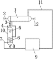
Fig. 1 is vacuum-pumping pipeline gas essential oil retracting device structural representation described in the utility model;
Wherein: 1. condenser, 2. vacuumize gas vent, 3. oil content collecting pipe, 4. blow-down pipe, 5. liquid level show on trial, 6. cooling coil, 7. cooling water inlet pipe, 8. liquid outlet, 9. refrigeration plant, 10. essential oil storage tank, 11. cooling water outlet pipes, 12. vacuumize gas access.
The specific embodiment
Below in conjunction with the drawings and specific embodiments, the utility model is described further.
As shown in Figure 1, a kind of vacuum-pumping pipeline gas essential oil retracting device, comprise condenser 1, essential oil storage tank 10 and refrigeration plant 9, condenser 1 is located in vacuum-pumping pipeline, two ends with vacuumize gas access 12, vacuumizing gas vent 2 is connected, condenser 1 is provided with an oil content and collects mouth, oil content is collected mouth and is connected with essential oil storage tank 10 by oil content collecting pipe 3, in essential oil storage tank 10, be provided with cooling coil 6, refrigeration plant 9 is by cooling water inlet pipe 7 priority and cooling coils, the condensate liquid import of condenser 1 is connected, the condensate outlet of condenser connects refrigeration plant 9 by cooling water return duct 11, in addition essential oil storage tank 10 is provided with a blow-down pipe 4 and a liquid level visor 5, essential oil storage tank 10 bottoms are provided with a liquid outlet 8.
Vacuum-pumping pipeline gas essential oil retracting device operation principle described in the utility model is: in vacuum line, condenser is installed, condenser becomes the part of vacuum line, the frozen liq being produced by refrigerator 9 (5-20 ℃) is delivered to condenser by pipeline, vacuum gas by condenser is carried out cooling, condensation, oil content in this process in vacuum gas changes liquid condition into by gaseous state, flow to the essential oil storage tank that cooling coil is installed, realize the recovery of essential oil in vacuum gas, in essential oil storage tank, cooling coil is installed simultaneously, its effect is to keep the essential oil reclaiming in low-temperature condition, prevent that secondary volatilization from appearring in the essential oil liquid of collecting.
During concrete use, when the gas vacuumizing passes through condenser, oil content in gas is after condensation, change liquid state into, by oil content collecting pipe, be collected in essential oil storage tank, when carrying out oil content collection, close the valve of oil content collecting pipe, open emptying valve, open the valve of liquid outlet, essential oil is discharged by outlet by withdrawal liquid; After liquid is drained, closing liquid outlet valve successively, blow-down pipe valve, opens collecting pipe valve, carries out oil content and again collects.
Although specifically show and introduced the utility model in conjunction with preferred embodiment; but those skilled in the art should be understood that; within not departing from the spirit and scope of the present utility model that appended claims limits; in the form and details the utility model is made a variety of changes, be protection domain of the present utility model.
Claims (4)
1. a vacuum-pumping pipeline gas essential oil retracting device, it is characterized in that: comprise condenser, essential oil storage tank and refrigeration plant, described condenser is located in vacuum-pumping pipeline, condenser is provided with an oil content and collects mouth, described oil content is collected mouth and is connected with essential oil storage tank by oil content collecting pipe, and described refrigeration plant is connected with condensate liquid import, the condensate outlet of condenser respectively by cooling water inlet pipe, cooling water outlet pipe.
2. vacuum-pumping pipeline gas essential oil retracting device according to claim 1, is characterized in that: in described essential oil storage tank, be provided with cooling coil, described cooling water inlet pipe first connects cooling coil, then connects condensate liquid import.
3. vacuum-pumping pipeline gas essential oil retracting device according to claim 1, is characterized in that: described essential oil storage tank is provided with a blow-down pipe, and described essential oil tank bottom is provided with a liquid outlet.
4. vacuum-pumping pipeline gas essential oil retracting device according to claim 1, is characterized in that: described essential oil storage tank is provided with a liquid level visor.
Priority Applications (1)
| Application Number | Priority Date | Filing Date | Title |
|---|---|---|---|
| CN201320526823.9U CN203408490U (en) | 2013-08-28 | 2013-08-28 | Vacuumizing pipeline gas essential oil recovery device |
Applications Claiming Priority (1)
| Application Number | Priority Date | Filing Date | Title |
|---|---|---|---|
| CN201320526823.9U CN203408490U (en) | 2013-08-28 | 2013-08-28 | Vacuumizing pipeline gas essential oil recovery device |
Publications (1)
| Publication Number | Publication Date |
|---|---|
| CN203408490U true CN203408490U (en) | 2014-01-29 |
Family
ID=49971418
Family Applications (1)
| Application Number | Title | Priority Date | Filing Date |
|---|---|---|---|
| CN201320526823.9U Expired - Lifetime CN203408490U (en) | 2013-08-28 | 2013-08-28 | Vacuumizing pipeline gas essential oil recovery device |
Country Status (1)
| Country | Link |
|---|---|
| CN (1) | CN203408490U (en) |
Cited By (3)
| Publication number | Priority date | Publication date | Assignee | Title |
|---|---|---|---|---|
| CN104059779A (en) * | 2014-06-27 | 2014-09-24 | 融安县金宜林生物技术有限责任公司 | Sarcandra glabra vacuum-drying and volatile oil separating method |
| CN114225616A (en) * | 2021-12-14 | 2022-03-25 | 中国船舶重工集团公司第七0三研究所 | Vacuum vortex retarding device |
| CN114307922A (en) * | 2021-12-22 | 2022-04-12 | 河南能源化工集团研究总院有限公司 | Device for synthesizing nitrous acid ester and production method thereof |
-
2013
- 2013-08-28 CN CN201320526823.9U patent/CN203408490U/en not_active Expired - Lifetime
Cited By (3)
| Publication number | Priority date | Publication date | Assignee | Title |
|---|---|---|---|---|
| CN104059779A (en) * | 2014-06-27 | 2014-09-24 | 融安县金宜林生物技术有限责任公司 | Sarcandra glabra vacuum-drying and volatile oil separating method |
| CN114225616A (en) * | 2021-12-14 | 2022-03-25 | 中国船舶重工集团公司第七0三研究所 | Vacuum vortex retarding device |
| CN114307922A (en) * | 2021-12-22 | 2022-04-12 | 河南能源化工集团研究总院有限公司 | Device for synthesizing nitrous acid ester and production method thereof |
Similar Documents
| Publication | Publication Date | Title |
|---|---|---|
| CN206008358U (en) | A kind of oil-gas recovery system utilizing condensation process | |
| CN102527073A (en) | Adsorption-condensation composite oil gas recovering device and oil gas recovering method | |
| CN203408490U (en) | Vacuumizing pipeline gas essential oil recovery device | |
| CN201454139U (en) | Oil-gas recovery processing device | |
| CN205618328U (en) | A combination equipment for preparing it is dry, clean gaseous | |
| CN205549656U (en) | Gaseous state solvent condensation recovery device | |
| CN203507779U (en) | Byproduct gas recycling system | |
| CN108144408A (en) | A kind of recovery system for organic solvent and its recovery method | |
| CN202289807U (en) | Adsorption and condensation technology-based organic vapor recovery unit | |
| CN204185513U (en) | RH refining furnace vacuum-pumping system | |
| CN208395104U (en) | A kind of condensation adsorption formula device for recovering oil and gas | |
| CN203501829U (en) | Steam condensate collection equipment with cooler | |
| CN202620765U (en) | Tail gas recovering complete equipment for rectifying tower | |
| CN202119171U (en) | Non-condensable gas collection device with gas collection tank | |
| CN202709577U (en) | Air extractor | |
| CN201969378U (en) | Adsorption-condensation combined oil gas recovery device | |
| CN203810809U (en) | Refrigerating system and gas exhausting device for same | |
| CN110657608A (en) | Recovery and filling machine for automobile air conditioner refrigerant and application thereof | |
| CN204159182U (en) | A kind of roasting method acid regeneration acid mist reclaiming clean device being provided with condenser | |
| CN207996563U (en) | A kind of processing unit of inorganization emptying exhaust gas | |
| CN205151819U (en) | Adopt air stripping method to get rid of device of ammonia in blue charcoal waste water | |
| CN205102582U (en) | Weary gas comdenstion water of brown coal desiccator and heat recovery system based on liquid - liquid heat exchanger | |
| CN208959580U (en) | A kind of carbon dioxide air accumulator residual gas recyclable device | |
| CN204550052U (en) | A kind of device improving the carclazyte bed working fluid rate of recovery | |
| CN201301225Y (en) | Sulfur dioxide recovery unit |
Legal Events
| Date | Code | Title | Description |
|---|---|---|---|
| C14 | Grant of patent or utility model | ||
| GR01 | Patent grant | ||
| CX01 | Expiry of patent term |
Granted publication date: 20140129 |
|
| CX01 | Expiry of patent term |