CN203377560U - A cable branch box support - Google Patents
A cable branch box support Download PDFInfo
- Publication number
- CN203377560U CN203377560U CN201320428140.XU CN201320428140U CN203377560U CN 203377560 U CN203377560 U CN 203377560U CN 201320428140 U CN201320428140 U CN 201320428140U CN 203377560 U CN203377560 U CN 203377560U
- Authority
- CN
- China
- Prior art keywords
- branch box
- cable branch
- pair
- shaped ring
- backing plate
- Prior art date
- Legal status (The legal status is an assumption and is not a legal conclusion. Google has not performed a legal analysis and makes no representation as to the accuracy of the status listed.)
- Expired - Lifetime
Links
Images
Abstract
The utility model discloses a cable branch box support and resolves problems of inconvenient field installation and poor firmness of a conventional cable branch box support. The cable branch box support comprises angle iron, a base plate (5), and a concrete electric pole (10). Small hoops (3) are disposed on the top end plate of the angle iron and are fixedly connected with the top end plate (1) of the angle iron through small hoop bolts (4). The base plate is welded on the bottom end face of a vertical plate (2) of the angle iron. A pair of U-shaped ring connecting holes (7) are disposed on the base plate. The two ends of a U-shaped ring (11) are respectively connected with a corresponding U-shaped ring connecting hole (7) disposed on the base plate through a U-shaped ring fixing bolt. A pair of triangular chucking protrusions (9) are symmetrically disposed on the bottom surface of the base plate. The concrete electric pole is clamped between the pair of triangular chucking protrusions and the inner side surface of the U-shaped ring. The cable branch box support with simple structure is easy to produce and has strong applicability.
Description
Technical field
The utility model relates to the cable branch box bracket on a kind of transmission line, particularly the mounting bracket of a kind of cable branch box on the concrete electric pole.
Background technology
On the concrete electric pole of transmission line, often want the installing cables feeder pillar, thickness difference due to the concrete electric pole, and the cable radical difference of cable branch box, on-the-spot installing cables feeder pillar is met difficulty, and existing cable branch box rack form is various, inconvenient on-the-spot installation, also there is defect in the fastness of support simultaneously, has had influence on the normal operation of transmission line.
Summary of the invention
The utility model provides a kind of cable branch box bracket, has solved on-the-spot the installation and the poor problem of fastness of inconvenience that existing cable branch box bracket exists.
The utility model is to solve by the following technical programs above technical problem:
A kind of cable branch box bracket, comprise angle steel, backing plate and concrete electric pole, be provided with little anchor ear on the upper head plate of angle steel, little anchor ear is fixed together by the upper head plate of little anchor ear bolt and angle steel, backing plate is fixedly welded on the bottom face of riser of angle steel, be provided with pair of U-shaped ring connecting hole on backing plate, the two ends of U-loop link together with the corresponding U-loop connecting hole arranged on backing plate by a U-loop set bolt respectively, be provided with symmetrically a pair of leg-of-mutton chucking projection on the bottom surface of backing plate, be connected with the concrete electric pole between the medial surface of a pair of leg-of-mutton chucking projection and U-loop.
Be welded with reinforcement between upper head plate and backing plate, the little anchor ear arranged on the upper head plate of angle steel has 4.
The utility model is simple in structure, is easy to install, and applicability is stronger, can be installed the electrical branch case of using on any bar, has improved operating efficiency, has alleviated staff's labour intensity.
The accompanying drawing explanation
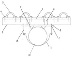
Fig. 1 is structural representation of the present utility model.
Embodiment
A kind of cable branch box bracket, comprise angle steel, backing plate 5 and concrete electric pole 10, be provided with little anchor ear 3 on the upper head plate 1 of angle steel, little anchor ear 3 is fixed together by little anchor ear bolt 4 and the upper head plate 1 of angle steel, backing plate 5 is fixedly welded on the bottom face of riser 2 of angle steel, be provided with pair of U-shaped ring connecting hole 7 on backing plate 5, the two ends of U-loop 11 link together with the corresponding U-loop connecting hole 7 arranged on backing plate 5 by a U-loop set bolt 8 respectively, be provided with symmetrically a pair of leg-of-mutton chucking projection 9 on the bottom surface of backing plate 5, be connected with concrete electric pole 10 between the medial surface of a pair of leg-of-mutton chucking projection 9 and U-loop 11.
Be welded with reinforcement 6 between upper head plate 1 and backing plate 5, the little anchor ear 3 arranged on the upper head plate 1 of angle steel has 4.
Claims (2)
1. a cable branch box bracket, comprise angle steel, backing plate (5) and concrete electric pole (10), be provided with little anchor ear (3) on the upper head plate (1) of angle steel, little anchor ear (3) is fixed together by little anchor ear bolt (4) and the upper head plate (1) of angle steel, backing plate (5) is fixedly welded on the bottom face of riser (2) of angle steel, it is characterized in that, be provided with pair of U-shaped ring connecting hole (7) on backing plate (5), the two ends of U-loop (11) link together by the upper corresponding U-loop connecting hole (7) arranged of a U-loop set bolt (8) and backing plate (5) respectively, be provided with symmetrically a pair of leg-of-mutton chucking projection (9) on the bottom surface of backing plate (5), be connected with concrete electric pole (10) between the medial surface of a pair of leg-of-mutton chucking projection (9) and U-loop (11).
2. a kind of cable branch box bracket according to claim 1, is characterized in that, between upper head plate (1) and backing plate (5), is welded with reinforcement (6), at the upper little anchor ear (3) arranged of the upper head plate (1) of angle steel, has 4.
Priority Applications (1)
| Application Number | Priority Date | Filing Date | Title |
|---|---|---|---|
| CN201320428140.XU CN203377560U (en) | 2013-07-18 | 2013-07-18 | A cable branch box support |
Applications Claiming Priority (1)
| Application Number | Priority Date | Filing Date | Title |
|---|---|---|---|
| CN201320428140.XU CN203377560U (en) | 2013-07-18 | 2013-07-18 | A cable branch box support |
Publications (1)
| Publication Number | Publication Date |
|---|---|
| CN203377560U true CN203377560U (en) | 2014-01-01 |
Family
ID=49840065
Family Applications (1)
| Application Number | Title | Priority Date | Filing Date |
|---|---|---|---|
| CN201320428140.XU Expired - Lifetime CN203377560U (en) | 2013-07-18 | 2013-07-18 | A cable branch box support |
Country Status (1)
| Country | Link |
|---|---|
| CN (1) | CN203377560U (en) |
Cited By (2)
| Publication number | Priority date | Publication date | Assignee | Title |
|---|---|---|---|---|
| CN108321746A (en) * | 2018-02-02 | 2018-07-24 | 国网湖北省电力有限公司随州供电公司 | A kind of pole grasp type distribution box fixing bracket and the distribution box mating with it |
| CN110376410A (en) * | 2019-07-31 | 2019-10-25 | 威胜电气有限公司 | A kind of anchor ear and ammeter box |
-
2013
- 2013-07-18 CN CN201320428140.XU patent/CN203377560U/en not_active Expired - Lifetime
Cited By (2)
| Publication number | Priority date | Publication date | Assignee | Title |
|---|---|---|---|---|
| CN108321746A (en) * | 2018-02-02 | 2018-07-24 | 国网湖北省电力有限公司随州供电公司 | A kind of pole grasp type distribution box fixing bracket and the distribution box mating with it |
| CN110376410A (en) * | 2019-07-31 | 2019-10-25 | 威胜电气有限公司 | A kind of anchor ear and ammeter box |
Similar Documents
| Publication | Publication Date | Title |
|---|---|---|
| CN203377560U (en) | A cable branch box support | |
| CN102996585B (en) | Embracing hoop applied transformer rack assembling method | |
| CN201853426U (en) | Identifying mark mounting structure for transmission line poles | |
| CN204441814U (en) | Cable testing bridge and use the crane span structure assembly of this cable testing bridge | |
| CN205244782U (en) | Can tensile TV set stores pylon | |
| CN201712435U (en) | Front support frame of back plate spring | |
| CN206054931U (en) | A kind of universal anchor ear | |
| CN203398707U (en) | Wire-bracing clamp | |
| CN202812477U (en) | Snap-in type cable support frame structure | |
| CN104242214A (en) | Universal fixing device for cross arm type mounting of large cross-section cable laying | |
| CN201931229U (en) | Narrow gap welding and fixing support for construction steel bar | |
| CN206017065U (en) | A kind of inside shelf support of kuppe | |
| CN203119673U (en) | Novel cable fixing structure | |
| CN203701586U (en) | Ring beam shaping device | |
| CN206903180U (en) | Upper suspension centre supporting structure | |
| CN202488079U (en) | Cable fastening clamp for large cross-section cable tunnel | |
| CN202217989U (en) | Connecting bracket device for installing base of tower controllable lightning conductor | |
| CN206859799U (en) | Special purpose device is changed in a kind of 500kV Guywire towers bracing wire | |
| CN204441815U (en) | Cable testing bridge hanging box and use the crane span structure assembly of this hanging box | |
| CN205677130U (en) | A kind of steel construction planted roof load-bearing purlin | |
| CN204626936U (en) | A kind of telescopic scaffold board for building | |
| CN204046500U (en) | Photovoltaic cable mounting structure | |
| CN201910582U (en) | Modified U-shaped combined cabinet connecting part | |
| CN205281000U (en) | Communication line erects and uses fixed fitting | |
| CN204156477U (en) | Electric cable with large cross-section lays the general fixing device that wish-bone arm type is installed |
Legal Events
| Date | Code | Title | Description |
|---|---|---|---|
| C14 | Grant of patent or utility model | ||
| GR01 | Patent grant | ||
| CX01 | Expiry of patent term | ||
| CX01 | Expiry of patent term |
Granted publication date: 20140101 |