CN203357077U - Hole-boring clamp of main speed reducer shell assembly of engineering truck - Google Patents
Hole-boring clamp of main speed reducer shell assembly of engineering truck Download PDFInfo
- Publication number
- CN203357077U CN203357077U CN 201320432534 CN201320432534U CN203357077U CN 203357077 U CN203357077 U CN 203357077U CN 201320432534 CN201320432534 CN 201320432534 CN 201320432534 U CN201320432534 U CN 201320432534U CN 203357077 U CN203357077 U CN 203357077U
- Authority
- CN
- China
- Prior art keywords
- engineering truck
- reducing gear
- hole
- main reducing
- gear housing
- Prior art date
- Legal status (The legal status is an assumption and is not a legal conclusion. Google has not performed a legal analysis and makes no representation as to the accuracy of the status listed.)
- Expired - Fee Related
Links
Images


Abstract
The utility model discloses a hole-boring clamp of a main speed reducer shell assembly of an engineering truck. The hole-boring clamp comprises a base ring, two cover plates, two supporting plates and a bottom plate, wherein the base ring, the two cover plates, the two supporting plates and the bottom plate are arranged in a stacked mode from top to bottom, the base ring is provided with a round center hole, the position, located below the center hole, of the bottom plate is provided with a tool through hole, and the two cover plates are arranged on the left side and the right side of the center hole. The hole-boring clamp is specially used for the main speed reducer shell assembly, and is simple in structure, convenient to operate and high in machining precision and qualified rate of finished products.
Description
Technical field
the utility model relates to a kind of frock clamp, is specifically related to a kind of engineering truck main reducing gear housing assy boring jig.
Background technology
main reducing gear is to reduce rotating speed in automotive transmission, utilize Bevel Gear Transmission to change power direction and to increase the critical piece of moment of torsion.Wherein, main reducing gear is comprised of differential assembly, speed reducer assembly (master, driven gear), main reducing gear housing assy etc., and the main reducing gear housing assy is the installation basis of differential assembly and speed reducer assembly.Must guarantee in main reducing gear that driving and driven gear has good engagement situation, just can make their good work.The correct engagement of main reducing gear middle gear, except the crudy with gear, equipment adjustment and bearing are relevant, also have close relationship with rigidity and the machining accuracy of main reducing gear housing assy.For the needs that assemble, the main reducing gear housing assy usually by final drive casing and pair of bearings, is covered and related fittings forms.
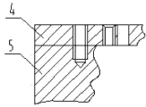
two dead eyes in the main reducing gear housing assy are that after final drive casing is connected with bearing cap, (structure is as Fig. 1) thick right boring forms, to guarantee the axiality in two bearings hole.For the clamping error of avoiding secondary clamping to bring, this procedure of processing is carried out on three hole boring machines, bores apical pore 1 and the centre bore 2 of final drive casing simultaneously.This bore hole operation need be used Special tooling clamp, to improve machining accuracy, process velocity and product qualified rate.
Summary of the invention
the engineering truck main reducing gear housing assy boring jig that the utility model purpose is to provide a kind of simple in structure, easy to operate, machining accuracy and product qualified rate is high, enhance productivity.
for achieving the above object, the technical solution adopted in the utility model is: a kind of engineering truck main reducing gear housing assy boring jig, comprise folded seat ring, two cover plates, two gripper shoes and the base plate of establishing up and down, described seat ring is provided with round center hole, the described base plate that is positioned at described centre bore below is provided with the cutter via hole, and two described cover plates are located at the left and right sides of described centre bore.
in technique scheme, described gripper shoe is the U-shaped plate, and two described gripper shoes are divided into the both sides, front and back of described cutter via hole, and the two ends of described cover plate are erected on respectively on two described gripper shoes.
in technique scheme, the inner side edge of two described cover plates is provided with the segmental arc isometrical with described centre bore.
in technique scheme, each described cover plate is provided with a fixed via, is provided with accordingly two locating holes on described seat ring.
preferably, described base plate is square plate, offers the described cutter via hole of rectangle on it.
in technique scheme, described seat ring is fixedly connected with described cover plate by 4 M8 screws.
in technique scheme, described base plate is fixedly connected with platen by 4 M20 bolts.
in technique scheme, the end of described cover plate is fixedly connected with described gripper shoe by the M12 screw.
utilize the operation of dead eye, apical pore and centre bore on the utility model boring processing final drive casing, comprise the steps:
(1) by workpiece with apical pore under, dead eye is located on boring jig at upper form seat;
(2) utilize screw that the large plane holder of workpiece is located between seat ring and cover plate, realize the location of workpiece;
(3) utilize three hole boring machines thick right boring dead eye, apical pore and centre bore successively, guarantee that the two bearings hole is with respect to apical pore axis symmetry, centre hole axis system is with respect to the offset distance of apical pore axis;
(4) take off the workpiece after processing on boring jig, complete the boring processing of final drive casing upper bearing (metal) hole, apical pore and centre bore.
because technique scheme is used, the advantage that the utility model compared with prior art has is:
1. the boring jig that the utility model is the final drive casing special use, simple in structure, easy to operate, machining accuracy and product qualified rate are high.
The accompanying drawing explanation
fig. 1 is the structural representation of final drive casing in background technology;
wherein: 1, apical pore; 2, centre bore;
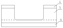
fig. 2 is the front view after the utility model embodiment mono-removes seat ring;
fig. 3 is the top view of Fig. 2;
fig. 4 is the right view of Fig. 2;
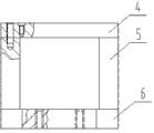
fig. 5 is the front view of seat ring in embodiment mono-;
fig. 6 is the cutaway view of A-A along the line in Fig. 5;
fig. 7 is the cutaway view at B place in Fig. 3;
wherein: 3, seat ring; 30, centre bore; 31, locating hole; 4, cover plate; 40, segmental arc; 41, fixed via; 5, gripper shoe; 6, base plate; 60, cutter via hole.
The specific embodiment
below in conjunction with drawings and Examples, the utility model is further described:
embodiment mono-: shown in Fig. 2 ~ 4, a kind of engineering truck main reducing gear housing assy boring jig, comprise folded seat ring 3, two cover plates 4, two gripper shoes 5 and the base plate 6 of establishing up and down, and described base plate 6 is fixedly connected with platen by 4 M20 bolts.
described base plate 6 is square plate, and the center offers the described cutter via hole 60 of rectangle.
described gripper shoe 5 is the U-shaped plate, and two described gripper shoes 5 are divided into the both sides, front and back of described cutter via hole 60.
described seat ring 3 is provided with round center hole 30, as shown in Figure 4 and Figure 5.Described cutter via hole 60 is positioned at the below of described centre bore 30, and two described cover plates 4 are located at the left and right sides of described centre bore 30, and the two ends of each described cover plate 4 are erected on respectively on two described gripper shoes 5.
the end of described cover plate 4 is fixedly connected with described gripper shoe 5 by the M12 screw; Described seat ring 3 is fixedly connected with described cover plate 4 by 4 M8 screws, sees Fig. 7.
the inner side edge of two described cover plates 4 is provided with the segmental arc 40 isometrical with described centre bore 30.
each described cover plate 4 is provided with a fixed via 41, is provided with accordingly two locating holes 31 on described seat ring 3, is convenient to assembling.
utilize the operation of dead eye, apical pore and centre bore on the present embodiment one boring processing final drive casing, comprise the steps:
(1) by workpiece with apical pore under, dead eye is located on boring jig at upper form seat;
(2) utilize screw that the large plane holder of workpiece is located between seat ring and cover plate, realize the location of workpiece;
(3) utilize three hole boring machines thick right boring dead eye, apical pore and centre bore successively, guarantee that the two bearings hole is with respect to apical pore axis symmetry, centre hole axis system is with respect to the offset distance of apical pore axis;
(4) take off the workpiece after processing on boring jig, complete the boring processing of final drive casing upper bearing (metal) hole, apical pore and centre bore.
the boring jig that the utility model is the final drive casing special use, simple in structure, easy to operate, machining accuracy and product qualified rate are high.
the above is preferred embodiment of the present utility model; should be understood that; for those skilled in the art; under the prerequisite that does not break away from principle described in the utility model; can also make some improvement or replacement, these improvement or replacement also should be considered as protection domain of the present utility model.
Claims (8)
1. an engineering truck main reducing gear housing assy boring jig, it is characterized in that: comprise folded seat ring (3), two cover plates (4), two gripper shoes (5) and the base plate (6) of establishing up and down, described seat ring (3) is provided with round center hole (30), the described base plate (6) that is positioned at described centre bore (30) below is provided with cutter via hole (60), and two described cover plates (4) are located at the left and right sides of described centre bore (30).
2. engineering truck main reducing gear housing assy boring jig according to claim 1, it is characterized in that: described gripper shoe (5) is the U-shaped plate, two described gripper shoes (5) are divided into the both sides, front and back of described cutter via hole (60), and the two ends of described cover plate (4) are erected on respectively on two described gripper shoes (5).
3. engineering truck main reducing gear housing assy boring jig according to claim 1 and 2, it is characterized in that: the inner side edge of two described cover plates (4) is provided with the segmental arc (40) isometrical with described centre bore (30).
4. engineering truck main reducing gear housing assy boring jig according to claim 1, it is characterized in that: each described cover plate (4) is provided with a fixed via (41), is provided with accordingly two locating holes (31) on described seat ring (3).
5. engineering truck main reducing gear housing assy boring jig according to claim 1, it is characterized in that: described base plate (6) is square plate, offers the described cutter via hole (60) of rectangle on it.
6. according to the described engineering truck main reducing gear of claim 1 or 4 housing assy boring jig, it is characterized in that: described seat ring (3) is fixedly connected with described cover plate (4) by 4 M8 screws.
7. engineering truck main reducing gear housing assy boring jig according to claim 1 or 5, it is characterized in that: described base plate (6) is fixedly connected with platen by 4 M20 bolts.
8. engineering truck main reducing gear housing assy boring jig according to claim 2, it is characterized in that: the end of described cover plate (4) is fixedly connected with described gripper shoe (5) by the M12 screw.
Priority Applications (1)
| Application Number | Priority Date | Filing Date | Title |
|---|---|---|---|
| CN 201320432534 CN203357077U (en) | 2013-07-21 | 2013-07-21 | Hole-boring clamp of main speed reducer shell assembly of engineering truck |
Applications Claiming Priority (1)
| Application Number | Priority Date | Filing Date | Title |
|---|---|---|---|
| CN 201320432534 CN203357077U (en) | 2013-07-21 | 2013-07-21 | Hole-boring clamp of main speed reducer shell assembly of engineering truck |
Publications (1)
| Publication Number | Publication Date |
|---|---|
| CN203357077U true CN203357077U (en) | 2013-12-25 |
Family
ID=49804898
Family Applications (1)
| Application Number | Title | Priority Date | Filing Date |
|---|---|---|---|
| CN 201320432534 Expired - Fee Related CN203357077U (en) | 2013-07-21 | 2013-07-21 | Hole-boring clamp of main speed reducer shell assembly of engineering truck |
Country Status (1)
| Country | Link |
|---|---|
| CN (1) | CN203357077U (en) |
Cited By (1)
| Publication number | Priority date | Publication date | Assignee | Title |
|---|---|---|---|---|
| CN105945607A (en) * | 2016-06-30 | 2016-09-21 | 江苏汤臣汽车零部件有限公司 | Machining tool for light electric vehicle speed reducer right shell |
-
2013
- 2013-07-21 CN CN 201320432534 patent/CN203357077U/en not_active Expired - Fee Related
Cited By (1)
| Publication number | Priority date | Publication date | Assignee | Title |
|---|---|---|---|---|
| CN105945607A (en) * | 2016-06-30 | 2016-09-21 | 江苏汤臣汽车零部件有限公司 | Machining tool for light electric vehicle speed reducer right shell |
Similar Documents
| Publication | Publication Date | Title |
|---|---|---|
| CN105619117A (en) | Milling clamp for thin-wall shifting forks | |
| CN104476242A (en) | Auxiliary tool used for positioning electric multiple unit framework on computer numerical control planer type milling machine | |
| CN202984717U (en) | Large cast full-automatic machining boring-milling machine | |
| CN102873365A (en) | Full-automatic processing boring-milling machine for large castings | |
| CN102773718B (en) | Rotating machinery processing work platform | |
| CN203357077U (en) | Hole-boring clamp of main speed reducer shell assembly of engineering truck | |
| CN104889764A (en) | Boring fixture of main speed reducer shell assembly of engineering truck | |
| CN202278242U (en) | Universal adapter frame of face milling cutter | |
| CN202344224U (en) | Machine tool for processing radial holes on shell of differential mechanism | |
| CN202097417U (en) | Convenience tool rest for lathe | |
| CN206047590U (en) | A kind of automobile shafts fork face punching and shaving special purpose machine tool | |
| CN204658034U (en) | A kind of air-actuated jaw of fast clamp crankshaft-link rod | |
| CN204053059U (en) | Can the angle square milling head of two-way clamping cutter | |
| CN204584822U (en) | Spring seat coach hole tool | |
| CN103084890B (en) | Punching machine bremsbelage processing tool and using method thereof | |
| CN203357074U (en) | Outer-circle turning clamp of main speed reducer shell assembly of engineering truck | |
| CN204160203U (en) | The two eccentric fixture of high accuracy | |
| CN204209475U (en) | Work piece holder frock in a kind of inserts process | |
| CN203853796U (en) | Space-saving type automatic turning clamp | |
| CN203356670U (en) | Reaming clamp of peripheral holes of main speed reducer shell of engineering truck | |
| CN202240533U (en) | Special tool for boring and milling main transmission seat | |
| CN203712346U (en) | Tool used for clamping special-shaped flange on vertical lathe | |
| CN203712347U (en) | Tool used for clamping special-shaped flange on vertical lathe | |
| CN203357076U (en) | Two-surface milling clamp of main speed reducer shell of engineering truck | |
| CN203356782U (en) | Tapping clamp of ring hole of thread ring base of main speed reducer of engineering truck |
Legal Events
| Date | Code | Title | Description |
|---|---|---|---|
| C14 | Grant of patent or utility model | ||
| GR01 | Patent grant | ||
| CF01 | Termination of patent right due to non-payment of annual fee | ||
| CF01 | Termination of patent right due to non-payment of annual fee |
Granted publication date: 20131225 Termination date: 20160721 |