CN203294486U - Steel-ball roller positioning device - Google Patents
Steel-ball roller positioning device Download PDFInfo
- Publication number
- CN203294486U CN203294486U CN201320355899XU CN201320355899U CN203294486U CN 203294486 U CN203294486 U CN 203294486U CN 201320355899X U CN201320355899X U CN 201320355899XU CN 201320355899 U CN201320355899 U CN 201320355899U CN 203294486 U CN203294486 U CN 203294486U
- Authority
- CN
- China
- Prior art keywords
- locating plate
- ball roller
- hole
- steel ball
- groove
- Prior art date
- Legal status (The legal status is an assumption and is not a legal conclusion. Google has not performed a legal analysis and makes no representation as to the accuracy of the status listed.)
- Expired - Fee Related
Links
Images
Landscapes
- Rollers For Roller Conveyors For Transfer (AREA)
Abstract
The utility model relates to a steel-ball roller positioning device comprising a bearing seat and a positioning components mounted on the bearing seat. The positioning components comprises a first positioning plate, a second positioning plate and a third positioning plate, a first through hole and a second through hole are formed on the first positioning plate and the second positioning plate respectively, and the first through hole is communicated with the second through hole. The steel-ball roller positioning device is simple and practical, operation is facilitated, the steel-ball roller can be positioned rapidly, positioning is stable, shaking and impacting of products during transportation are reduced, quality of the steel-ball roller is guaranteed, and production cost of a company is lowered.
Description
Technical field
The utility model relates to a kind of registration device, relates in particular to a kind of steel ball roller locator device.
Background technology
The steel ball roller is for the driving device on the automatic production line on belt conveyor, is the very important metal fittings of automatic assembly line, and it adopts stainless steel, has the very precision of standard.But the steel ball roller easily produces and rolls in transportation, cause the mutual collision between the steel ball roller, appearance is damaged, damaged the quality of steel ball roller, can't use, increase the productive costs of enterprise, therefore, be badly in need of a kind of device that can the positioning ball roller, guarantee the quality of steel ball roller.
The utility model content
The utility model has overcome the deficiencies in the prior art, and a kind of steel ball roller locator device simple in structure is provided.
For achieving the above object, the technical solution adopted in the utility model is: a kind of steel ball roller locator device, comprise load bearing seat, be arranged on the positioning component on described load bearing seat, described positioning component comprises the first locating plate, the second locating plate, the 3rd locating plate that sets gradually from top to bottom, on described the first locating plate, the second locating plate, have the first through hole, the second through hole, described the first through hole connects described the second through hole.
In preferred embodiment of the utility model, the steel ball roller locator device further comprises on described load bearing seat and has the first groove, and the antetheca of described the first groove runs through described load bearing seat.
In preferred embodiment of the utility model, the steel ball roller locator device further comprises on the diapire of described the first groove and is provided with projection, between the rear wall of the rear end of described projection and described the first groove, is connected with dividing plate.
In preferred embodiment of the utility model, the steel ball roller locator device comprises that further the center, lower end of described the 3rd locating plate has the second groove, and the rear end of described dividing plate is positioned at described the second groove.
In preferred embodiment of the utility model, the steel ball roller locator device comprises that further described the first locating plate, the second locating plate, the length of the 3rd locating plate, thickness increase successively, and the width of described the first locating plate, the second locating plate, the 3rd locating plate equates.
In preferred embodiment of the utility model, the steel ball roller locator device comprises that further described the first through hole, the second through hole all are square.
In preferred embodiment of the utility model, the steel ball roller locator device comprises that further described the first through hole is identical with the width of described the second through hole.
The utility model has solved the defect that exists in the background technology, and the utility model is simple and practical, and is easy to operate, the positioning ball roller, locate firmly fast, reduced product rocking and colliding in transportation, guarantee the quality of steel ball roller, reduced the productive costs of enterprise.
The accompanying drawing explanation
Below in conjunction with drawings and Examples, the utility model is further illustrated.
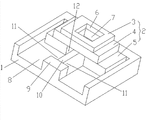
Fig. 1 is the structural representation of preferred embodiment of the present utility model;
In figure: 1, load bearing seat, 2, positioning component, the 3, first locating plate, the 4, second locating plate, the 5, the 3rd locating plate, the 6, first through hole, the 7, second through hole, the 8, first groove, 9, projection, 10, dividing plate, 11, corner, the 12, second groove.
The specific embodiment
In conjunction with the accompanying drawings and embodiments the utility model is described in further detail now, these accompanying drawings are the schematic diagram of simplification, basic structure of the present utility model only is described in a schematic way, so it only show the formation relevant with the utility model.
As shown in Figure 1, a kind of steel ball roller locator device, comprise load bearing seat 1, be arranged on the positioning component 2 on load bearing seat 1, load bearing seat 1 is rectangular, positioning component 2 comprises the first locating plate 3, the second locating plate 4, the 3rd locating plate 5 that sets gradually from top to bottom, on the first locating plate 3, the second locating plate 4, have the first through hole 6, second through hole 7, the first through holes 6 perforation the second through holes 7.
The antetheca that has the first groove 8, the first grooves 8 on the preferred load bearing seat 1 of the utility model runs through load bearing seat 1.
On the diapire of the first groove 8, be provided with projection 9, the front end face of projection 9 and the front end face of load bearing seat 1 are at grade, between the rear end of projection 9 and the rear wall of the first groove 8, be connected with dividing plate 10, dividing plate 10 is vertical setting with projection 9, and dividing plate 10 forms two corners 11 with projection 9.
The center, lower end of preferred the 3rd locating plate 5 of the utility model has the second groove 12, and the rear end of dividing plate 10 is positioned at the second groove 12.
In order to improve the steadiness of registration device, the first locating plate 3, the second locating plate 4, the length of the 3rd locating plate 5, thickness increase successively, and the width of the first locating plate 3, the second locating plate 4, the 3rd locating plate 5 equates.
For the steel ball roller is fixed, can not cause stress to concentrate simultaneously, the first through hole 6, the second through hole 7 all are square.The first through hole 6 is identical with the width of the second through hole 7.
The utility model in use, the vertical placement of steel ball roller can be snapped in the first through hole 6, the second through hole 7, other steel ball roller is laterally placed and snapped in the first groove 8, the end of steel ball roller is blocked by corner 11, can in the first groove 8, not skid off, steel ball roller location is firm, has guaranteed the quality of steel ball roller.
Above foundation desirable embodiment of the present utility model is enlightenment, and by above-mentioned description, the related personnel can, in the scope that does not depart from this utility model technological thought, carry out various change and modification fully.The technical scope of this utility model is not limited to the content on specification sheets, must determine technical scope according to the claim scope.
Claims (7)
1. steel ball roller locator device, it is characterized in that: comprise load bearing seat, be arranged on the positioning component on described load bearing seat, described positioning component comprises the first locating plate, the second locating plate, the 3rd locating plate that sets gradually from top to bottom, on described the first locating plate, the second locating plate, have the first through hole, the second through hole, described the first through hole connects described the second through hole.
2. steel ball roller locator device according to claim 1, it is characterized in that: on described load bearing seat, have the first groove, the antetheca of described the first groove runs through described load bearing seat.
3. steel ball roller locator device according to claim 2, is characterized in that: on the diapire of described the first groove, be provided with projection, between the rear wall of the rear end of described projection and described the first groove, be connected with dividing plate.
4. steel ball roller locator device according to claim 3, it is characterized in that: the center, lower end of described the 3rd locating plate has the second groove, and the rear end of described dividing plate is positioned at described the second groove.
5. steel ball roller locator device according to claim 1, it is characterized in that: described the first locating plate, the second locating plate, the length of the 3rd locating plate, thickness increase successively, and the width of described the first locating plate, the second locating plate, the 3rd locating plate equates.
6. steel ball roller locator device according to claim 1, it is characterized in that: described the first through hole, the second through hole all are square.
7. steel ball roller locator device according to claim 6, it is characterized in that: described the first through hole is identical with the width of described the second through hole.
Priority Applications (1)
| Application Number | Priority Date | Filing Date | Title |
|---|---|---|---|
| CN201320355899XU CN203294486U (en) | 2013-06-21 | 2013-06-21 | Steel-ball roller positioning device |
Applications Claiming Priority (1)
| Application Number | Priority Date | Filing Date | Title |
|---|---|---|---|
| CN201320355899XU CN203294486U (en) | 2013-06-21 | 2013-06-21 | Steel-ball roller positioning device |
Publications (1)
| Publication Number | Publication Date |
|---|---|
| CN203294486U true CN203294486U (en) | 2013-11-20 |
Family
ID=49570518
Family Applications (1)
| Application Number | Title | Priority Date | Filing Date |
|---|---|---|---|
| CN201320355899XU Expired - Fee Related CN203294486U (en) | 2013-06-21 | 2013-06-21 | Steel-ball roller positioning device |
Country Status (1)
| Country | Link |
|---|---|
| CN (1) | CN203294486U (en) |
Cited By (1)
| Publication number | Priority date | Publication date | Assignee | Title |
|---|---|---|---|---|
| CN103287683A (en) * | 2013-06-21 | 2013-09-11 | 苏州速腾电子科技有限公司 | Steel ball idler wheel locating device |
-
2013
- 2013-06-21 CN CN201320355899XU patent/CN203294486U/en not_active Expired - Fee Related
Cited By (1)
| Publication number | Priority date | Publication date | Assignee | Title |
|---|---|---|---|---|
| CN103287683A (en) * | 2013-06-21 | 2013-09-11 | 苏州速腾电子科技有限公司 | Steel ball idler wheel locating device |
Similar Documents
| Publication | Publication Date | Title |
|---|---|---|
| CN203470709U (en) | Sheet positioning and inducing device for cold-punching mold | |
| CN203294486U (en) | Steel-ball roller positioning device | |
| CN206614891U (en) | Mould under a kind of laminating apparatus with adjustable positioning portion | |
| CN203514578U (en) | Glass curtain wall and connecting structure thereof | |
| CN205888972U (en) | TV set frame equipment anchor clamps | |
| CN103287683B (en) | Steel ball roller locator device | |
| CN204896787U (en) | Liftable and positioning mechanism of tight part of clamp | |
| CN201268020Y (en) | Die carrier for locating screw on beach chair | |
| CN203956362U (en) | Planarity adjustment mechanism during for guide rails assembling | |
| CN104384374B (en) | A kind of stock shelf that reduces laser assembly solder plate slab and thin plate drop | |
| CN203992891U (en) | A kind of fore-telling type welding tooling | |
| CN208178719U (en) | A kind of split type big width laser cutting off machine | |
| CN203739333U (en) | High-precision and efficient embossing unit | |
| CN204093995U (en) | A kind of stock shelf reducing laser assembly solder plate slab and thin plate drop | |
| CN206443465U (en) | A kind of environmentally friendly dining chair | |
| CN201960203U (en) | Trimming and shearing device of plate shearing machine | |
| CN205343814U (en) | 3D printer rack construction | |
| CN205057314U (en) | A cutting positioner for laser cutting machine | |
| CN203997569U (en) | A kind of block that connects freight container headstock and drag case | |
| CN203557382U (en) | Manipulator facilitating stable transportation of screw rod | |
| CN202322227U (en) | Improved pedal bracket | |
| CN203462700U (en) | Keel for outdoor floor | |
| CN201757105U (en) | Movable eccentric connecting part | |
| CN203439754U (en) | Multi-chip feeder | |
| CN203566144U (en) | Welding equipment for rear frame of road roller |
Legal Events
| Date | Code | Title | Description |
|---|---|---|---|
| C14 | Grant of patent or utility model | ||
| GR01 | Patent grant | ||
| CF01 | Termination of patent right due to non-payment of annual fee |
Granted publication date: 20131120 Termination date: 20140621 |
|
| EXPY | Termination of patent right or utility model |