CN203286329U - LED (light-emitting diode) lamp - Google Patents
LED (light-emitting diode) lamp Download PDFInfo
- Publication number
- CN203286329U CN203286329U CN2013202823894U CN201320282389U CN203286329U CN 203286329 U CN203286329 U CN 203286329U CN 2013202823894 U CN2013202823894 U CN 2013202823894U CN 201320282389 U CN201320282389 U CN 201320282389U CN 203286329 U CN203286329 U CN 203286329U
- Authority
- CN
- China
- Prior art keywords
- led lamp
- lampshade
- lamp substrate
- substrate
- led
- Prior art date
- Legal status (The legal status is an assumption and is not a legal conclusion. Google has not performed a legal analysis and makes no representation as to the accuracy of the status listed.)
- Expired - Fee Related
Links
Images

Abstract
The utility model discloses an LED (light-emitting diode) lamp. The LED lamp comprises a lamp base (10) and a lampshade (20), and also comprises an LED lamp substrate (30) which is vertically arranged inside the lampshade (20) and used for installing LED beads (31), wherein the LED beads (31) are distributed on the outer end surface of the LED lamp substrate (30), and the LED beads (31) form an annular LED lamp light source inside the lampshade (20). By adopting the LED lamp, the light illuminating angle range of the LED beads inside the lampshade can be greatly enlarged, the illuminating effect can be improved, and the problem of the limited illuminating angle caused by the light emission of the traditional LED lamp from the bottom surface can be solved.
Description
Technical field
The utility model relates to a kind of light fixture, especially relates to a kind of LED of use lamp and makes the LED lamp of illumination light-emitting light source.
Background technology
LED is the advantages such as brightness is high, power consumption is low, long service life because having, and the fields such as lighting and electronic installation that are widely used in are as illuminating source.
Traditional LED lamp comprises lamp holder, the cooling base that is fixedly connected with lamp holder, be arranged on the power supply in cooling base, the other end of cooling base arranges lamp socket, be covered with circuit board on lamp socket, LED chip is installed on circuit board, this LED lamp is because the circuit board bottom angle that is on lamp socket upwards spreads luminous, usually the limitation due to structure itself causes final lighting angle to be restricted, and can not reach the more luminous lighting effect of wide-angle.
the day for announcing is that the granted patent numbers 201220061635.9 on December 19th, 2012 discloses a kind of candle lamp, comprise the candle type lampshade, LED chip, lamp socket, cooling base, power supply and lamp holder, described lamp socket is fixed between lampshade and cooling base, described LED chip is positioned at described lampshade and is fixed on lamp socket, described power supply is arranged in cooling base, described candle lamp also comprises can make the light that LED chip sends that the leaded light mirror that reflects or reflect occurs, described leaded light mirror is arranged in lampshade, one end of leaded light mirror is provided with the cavity that is complementary with the LED chip light output end, the cavity cover of leaded light mirror is on the light output end of LED chip.Although this structure is utilized reflection and the refraction principle of leaded light mirror, the light that LED chip sends after transmitting in the leaded light mirror, then exposes to lampshade, then evenly disperses illumination; Yet the circuit board of LED chip and installation LED chip is tiling to be arranged on lamp socket, and the LED lamp light angle that still exists whole candle lamp is restricted, and can not reach the more luminous lighting effect of wide-angle.
The utility model content
The utility model is restricted for the existing LED lamp of solution exists LED lamp light angle, a kind of traditional LED lamp restricted problem of the luminous light angle that causes that makes progress from bottom surface that solves that can not reach the present situation such as luminous lighting effect of wide-angle more and provide, can improve to a greater extent the illumination light efficiency, enlarge the LED lamp of light angle.
The utility model is to solve the problems of the technologies described above the concrete technical scheme that adopts to be: a kind of LED lamp, comprise bulb socket and lampshade, it is characterized in that: also comprise and vertically be arranged on the LED lamp substrate that is used for mounted LED lamp bulb in lampshade, be distributed with LED lamp pearl on LED lamp substrate outer face, LED lamp pearl 31 distributes and forms the LED lamp illuminating source of ring-type in lampshade.Raising to a greater extent the lighting angular range of the LED lamp pearl in lampshade, improve illuminating effect, solved traditional LED lamp restricted problem of the luminous light angle that causes that makes progress from bottom surface.
As preferably, described LED lamp substrate adopts at least three LED lamp substrates to constitute, and polylith LED lamp substrate ring-type vertically is distributed in lampshade.Safeguard and improve larger convenience for the installing/dismounting of LED lamp, while avoiding breaking down, need the whole trouble that the demolition and maintenance operation brings of carrying out.
As preferably, described LED lamp substrate adopts cylindrical body.Also can consider to adopt individual LED lamp substrate to surround cylindrical body according to actual conditions and be fixed in lampshade, make structure simpler.
As preferably, described LED lamp substrate is vertical with bulb socket to be arranged, or becomes an inclination angle of upwards narrowing to be arranged in lampshade with the bulb socket upper surface.Improve the lighting angular range of the LED lamp pearl in lampshade, improve illuminating effect; The structure that tilts to narrow improves the light angle scope to a greater extent, makes the light more uniform diffusion of LED lamp pearl, and light-struck area is larger.
As preferably, be provided with heat-conducting piece in described lampshade, heat-conducting piece is connected with the radiator in being located at bulb socket, and the LED lamp substrate is located on heat-conducting piece.Improve the radiating effect of LED lamp pearl, make the more stable work of LED lamp pearl reliable, and then improve the service life of LED lamp pearl and whole LED lamp product.
As preferably, described LED lamp substrate is distributed with multilayer LED lamp pearl on short transverse.Multi-layers distributing can improve the light angle scope to a greater extent, makes simultaneously the light more uniform diffusion of LED lamp pearl.
As preferably, described LED lamp substrate upper end is provided with the 2nd LED lamp substrate that becomes horizontally set with the LED lamp substrate, and the 2nd LED lamp substrate upper surface is provided with towards the luminous top LED lamp pearl of lampshade top orientation.
, as preferably, be provided with lens cap above the LED lamp pearl of described top.Lens cap is used for improving the refracted ray effect, is conducive to loose more even of the light of lamp pearl, and the area of radiation is larger, make up the irradiation of side light pearly-lustre line less than dark zone, top.
As preferably, described bulb socket upper end is provided with LED lamp substrate holder, and LED lamp substrate bottom is fixed on LED lamp substrate holder by spacing collar.Spacing collar can prevent that the LED lamp substrate from down coming off, and plays position-limiting action, also can improve simultaneously the solder joint that prevents LED lamp pearl and contact the problems such as fault that produce with heat carrier.
As preferably, described LED lamp substrate, the 2nd LED lamp substrate adopt the aluminium base material.Improve heat-conducting effect, improve to a greater extent the job stability of LED lamp pearl.
The beneficial effects of the utility model are: raising to a greater extent the lighting angular range of the LED lamp pearl in lampshade, improve illuminating effect, solved traditional LED lamp restricted problem of the luminous light angle that causes that makes progress from bottom surface.The light more uniform diffusion of LED lamp pearl, light-struck area is larger.The lamp pearly-lustre line irradiation that solution makes up conventional LED lamp less than dark zone.
Description of drawings:
Below in conjunction with the drawings and specific embodiments, the utility model is described in further detail.
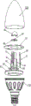
Fig. 1 is the structural representation of the preferred embodiment of the utility model LED lamp.
Fig. 2 is the perspective view of the utility model LED lamp.
The specific embodiment
Embodiment 1
In Fig. 1, embodiment shown in Figure 2, a kind of LED lamp, comprise bulb socket 10 and lampshade 20, also comprise and vertically be arranged on the LED lamp substrate 30 that is used for mounted LED lamp bulb 31 in lampshade 20, be distributed with LED lamp pearl 31 on LED lamp substrate 30 outer faces, LED lamp pearl 31 is adopted paster LED lamp pearl, and LED lamp pearl 31 forms the LED lamp illuminating source of ring-type in the interior distribution of lampshade 20.LED lamp substrate 30 adopts six LED lamp substrates to constitute, and six LED lamp substrate 30 ring-types vertically are distributed in lampshade 20.Can certainly select the LED lamp substrate 30 of other quantity to enclose to form according to actual conditions the LED lamp installation base plate of ring-type, such as the quantity such as 5,8,12.LED lamp substrate 30 becomes an inclination angle of upwards narrowing to be arranged in lampshade 20 with bulb socket 10 upper surfaces, reaches further raising light angle scope, makes the light more uniform diffusion of LED lamp pearl, and light-struck area is larger.Can certainly be LED lamp substrate 30 setting vertical with bulb socket 10, make mounting structure more simple.Heat-conducting piece 50 with LED lamp substrate 30 respective amount is installed in lampshade 20, on heat-conducting piece 50, both sides have the flange 51 of projection, LED lamp substrate 30 is arranged in the two formed grooves of side flange 51, improve to a greater extent heat-conducting effect, heat-conducting piece 50 is connected with the radiator in being arranged on bulb socket 10, and LED lamp substrate 30 is arranged on heat-conducting piece 50.LED lamp substrate 30 is distributed with five layers of LED lamp pearl 31 on short transverse, can certainly need situation according to reality use and cost, sets other different numbers of plies and meets different situations.LED lamp substrate 30 upper ends are equipped with the 2nd LED lamp substrate 33, the two LED lamp substrate 33 upper surfaces of 30 one-tenth horizontally sets of LED lamp substrate and are equipped with towards the luminous top LED lamp pearl 41 of lampshade 20 top orientation.LED lamp pearl 41 tops, top are provided with lens cap 42.The 2nd LED lamp substrate 33 centers are equipped with the mounting base 40 of LED lamp pearl 41, and mounting base 40 adopts the aluminium base material.Bulb socket 10 upper ends are equipped with LED lamp substrate holder 21, and LED lamp substrate 30 bottoms are fixed on LED lamp substrate holder 21 by spacing collar 32.LED lamp substrate 30, the 2nd LED lamp substrate 33 adopt the aluminium base material.Lampshade 20 adopts the sharper crown shape lampshades such as bullet shape in top, is arranged on picture candle lamp shape on bulb socket 10.
Embodiment 2:
Although this paper has more used the terms such as bulb socket, lampshade, LED lamp pearl, LED lamp substrate, lens cap; But do not get rid of the possibility of using other term.Using these terms is only in order to describe more easily and explain essence of the present invention; They are construed to any additional restriction is all contrary with spirit of the present invention.
Claims (10)
1. LED lamp, comprise bulb socket (10) and lampshade (20), it is characterized in that: also comprise and vertically be arranged on the LED lamp substrate (30) that is used for mounted LED lamp bulb (31) in lampshade (20), LED lamp substrate (30) is distributed with LED lamp pearl (31) on outer face, and LED lamp pearl (31) distributes and forms the LED lamp illuminating source of ring-type in lampshade (20).
2., according to LED lamp claimed in claim 1, it is characterized in that: described LED lamp substrate (30) adopts at least three LED lamp substrates to constitute, and polylith LED lamp substrate (30) ring-type vertically is distributed in lampshade (20).
3., according to LED lamp claimed in claim 1, it is characterized in that: described LED lamp substrate (30) adopts cylindrical body.
4., according to claim 1 or 2 or 3 described LED lamps, it is characterized in that: described LED lamp substrate (30) and the vertical setting of bulb socket (10), or with bulb socket (10) upper surface, become an inclination angle of upwards narrowing to be arranged in lampshade (20).
5., according to LED lamp claimed in claim 1, it is characterized in that: be provided with heat-conducting piece (50) in described lampshade (20), heat-conducting piece (50) is connected with the radiator in being located at bulb socket (10), and LED lamp substrate (30) is located on heat-conducting piece (50).
6. according to LED lamp claimed in claim 1, it is characterized in that: described LED lamp substrate (30) upper end is provided with the 2nd LED lamp substrate (33) that becomes horizontally set with LED lamp substrate (30), and the 2nd LED lamp substrate (33) upper surface is provided with towards the luminous top LED lamp pearl (41) of lampshade (20) top orientation.
7., according to LED lamp claimed in claim 6, it is characterized in that: described top LED lamp pearl (41) top is provided with lens cap (42).
8. according to claim or 2 or 3 or 5 or 6 described LED lamps, it is characterized in that: described LED lamp substrate (30) is distributed with multilayer LED lamp pearl (31) on short transverse.
9., according to LED lamp claimed in claim 1, it is characterized in that: described bulb socket (10) upper end is provided with LED lamp substrate holder (21), and LED lamp substrate (30) bottom is fixed on LED lamp substrate holder (21) by spacing collar (32).
10., according to claim 1 or 2 or 3 or 5 or 6 or 9 described LED lamps, it is characterized in that: described LED lamp substrate (30), the 2nd LED lamp substrate (33) adopt the aluminium base material.
Priority Applications (1)
| Application Number | Priority Date | Filing Date | Title |
|---|---|---|---|
| CN2013202823894U CN203286329U (en) | 2013-05-22 | 2013-05-22 | LED (light-emitting diode) lamp |
Applications Claiming Priority (1)
| Application Number | Priority Date | Filing Date | Title |
|---|---|---|---|
| CN2013202823894U CN203286329U (en) | 2013-05-22 | 2013-05-22 | LED (light-emitting diode) lamp |
Publications (1)
| Publication Number | Publication Date |
|---|---|
| CN203286329U true CN203286329U (en) | 2013-11-13 |
Family
ID=49542690
Family Applications (1)
| Application Number | Title | Priority Date | Filing Date |
|---|---|---|---|
| CN2013202823894U Expired - Fee Related CN203286329U (en) | 2013-05-22 | 2013-05-22 | LED (light-emitting diode) lamp |
Country Status (1)
| Country | Link |
|---|---|
| CN (1) | CN203286329U (en) |
Cited By (1)
| Publication number | Priority date | Publication date | Assignee | Title |
|---|---|---|---|---|
| CN106989341A (en) * | 2017-04-26 | 2017-07-28 | 易国庆 | Colour mixture temperature car headlight device design method |
-
2013
- 2013-05-22 CN CN2013202823894U patent/CN203286329U/en not_active Expired - Fee Related
Cited By (1)
| Publication number | Priority date | Publication date | Assignee | Title |
|---|---|---|---|---|
| CN106989341A (en) * | 2017-04-26 | 2017-07-28 | 易国庆 | Colour mixture temperature car headlight device design method |
Similar Documents
| Publication | Publication Date | Title |
|---|---|---|
| CN203907265U (en) | LED (Light Emitting Diode) bulb lamp | |
| WO2015180307A1 (en) | Small-and-medium-diameter high-luminous-intensity led annular-irradiation signal lamp | |
| CN202008039U (en) | Big-angle LED lamp tube | |
| CN102128381B (en) | LED (Light-Emitting Diode) lamp bulb with high lighting effect | |
| CN102734645A (en) | Led projection lamp | |
| CN103867947A (en) | LED bulb lamp | |
| CN103353071A (en) | LED lamp emitting light in large angle | |
| CN101825263B (en) | Light-emitting diode lamp | |
| CN204099932U (en) | Illumination light source and lighting device | |
| CN201916737U (en) | LED illuminating lamp and LED illuminating tube | |
| CN202274316U (en) | LED (Light-emitting diode) lamp with convex light source | |
| CN201827748U (en) | Combined cylindrical LED lamp | |
| CN202140922U (en) | LED spotlight | |
| CN203286329U (en) | LED (light-emitting diode) lamp | |
| CN201593732U (en) | High-power LED street lamp | |
| CN101936458A (en) | Wide angle LED illumination luminaire | |
| CN201377713Y (en) | LED secondary light source | |
| CN206539912U (en) | A kind of novel LED bulb lamp | |
| CN201582661U (en) | LED spotlight | |
| CN202001879U (en) | Surface-mounted LED light source with lenses | |
| CN201582660U (en) | LED spot lamp | |
| CN104654079A (en) | High-performance 360-degree LED (Light-Emitting Diode) lamp | |
| CN108036243B (en) | LED ground lamp | |
| CN201428951Y (en) | Led lamp body | |
| CN201751683U (en) | Fancy LED lamp body |
Legal Events
| Date | Code | Title | Description |
|---|---|---|---|
| C14 | Grant of patent or utility model | ||
| GR01 | Patent grant | ||
| CF01 | Termination of patent right due to non-payment of annual fee |
Granted publication date: 20131113 Termination date: 20150522 |
|
| EXPY | Termination of patent right or utility model |