CN203273927U - Feeding device of straw particle combustion furnace - Google Patents
Feeding device of straw particle combustion furnace Download PDFInfo
- Publication number
- CN203273927U CN203273927U CN 201320121553 CN201320121553U CN203273927U CN 203273927 U CN203273927 U CN 203273927U CN 201320121553 CN201320121553 CN 201320121553 CN 201320121553 U CN201320121553 U CN 201320121553U CN 203273927 U CN203273927 U CN 203273927U
- Authority
- CN
- China
- Prior art keywords
- feeding device
- air outlet
- combustion furnace
- frame
- stander
- Prior art date
- Legal status (The legal status is an assumption and is not a legal conclusion. Google has not performed a legal analysis and makes no representation as to the accuracy of the status listed.)
- Expired - Fee Related
Links
Images


Landscapes
- Solid-Fuel Combustion (AREA)
Abstract
The utility model relates to a feeding device of a combustion furnace, and particularly relates to a feeding device of a straw particle combustion furnace. The feeding device comprises a stander, a trapezoidal hopper arranged at the upper end of the stander, a material pushing auger arranged at a discharge hole end of the lower side of the trapezoidal hopper, a speed reducing motor connected with one end of the material pushing auger, a discharging pipe connected with the other end of the material pushing auger, a draught fan arranged at the bottom of the stander and an air barrel which is connected with the draught fan and provided with an air outlet end, wherein the air outlet end is of a tubular structure with one blocked end and is arranged vertical to the air barrel; and the air outlet end is provided with a plurality of air outlet holes. The feeding device is simple and reasonable, convenient to use, time-saving, labor-saving, good in combustion effect, free of smoke and dust pollution and high in degree of automation, and the labor intensity of operators can be reduced.
Description
Technical field
The utility model relates to a kind of feed arrangement, specifically a kind of stalk particle burning stove feed arrangement.
Background technology
Stalk is left cauline leaf or the tendril of the product of various crops in agricultural products.In recent years, due to crop straw burning, particularly the stalk of agricultural leftover is incinerated as rubbish, environment has been caused seriously influence, and a large amount of remaining stalks do not obtain rational development and utilization.
Scientific and technological development along with China's industry in recent years, the energy, electric power, research finds that stalk resource is abundant, recyclability is strong, the utilization of stalk not only can be alleviated the nervous situation of the energy, electricity supply and demand, also helps the biomass resource that improves environment and reasonably utilize sustainable development.Living beings are the fourth-largest energy that is only second to coal, oil, natural gas, account for 14% in the world energy sources aggregate consumption.The annual crop stalk stock number of China account for the Biomass Energy Resources amount near half, the stalk using energy source is one of main path of agricultural crop straw comprehensive utilization.
Stalk is cut up with a hay cutter into cun a high temperature granulating after section, make its density reach 1.0 1 1.2 water content 10 one 13%, caloric value 3,800 one 4500 kilocalorie/kilograms.Can be directly as Industrial Boiler fuel and domestic fuel.Stalk granular fuel is not only easily lighted, and flame is vigorous, and flare is stable, and the nuisance such as sulfur-bearing and phosphorus not in flue gas, and ashes can also be done the plant ash raw material.
Northern area in China has had some peasant households to adopt the stalk particle material to replace traditional fuel such as coal and timber as warming and life fuel at present, what be complementary with it is that some producers also develop some in succession for small home boiler and the warming stove of stalk particle material, but because also there are some irrational places in its structure, particularly there is no good supporting charging charging gear, so people need manually add granular fuel in use, automaticity is low, waste time and energy, labour intensity is large, contaminated environment.
Summary of the invention
The purpose of this utility model be to provide a kind of simple and reasonable, easy to use, time saving and energy saving, labour intensity, combustion efficiency that can alleviate the operator are good, smoke dust contaminated environment, stalk particle material combustion furnace feed arrangement that automaticity is high.
The purpose of this utility model is to realize like this, this feed arrangement comprises frame, be arranged on the trapezoidal hopper of frame upper end, be arranged on the pusher auger of discharge port end below trapezoidal hopper, the reducing motor that connects pusher auger one end, the drainage conduit that is connected to the pusher auger other end, the blower fan that is arranged on the frame bottom, connecting fan be with the air duct of outlet air end, described outlet air end is a tubular structure that an end blocks, perpendicular to the air duct setting, on it with a plurality of exhaust vents.
The periphery of described frame is provided with housing, is provided with the time switch and the time switch of controlling reducing motor of control blower fan in a side of housing.
The utility model is owing to adopting said structure to make the stalk particle material to be added in combustion furnace by automatic powder adding, feed and feeding quantity are accurately controlled, have that advantages of simple, labour intensity, combustion efficiency easy to use, time saving and energy saving, that can alleviate the operator are good, a smoke dust contaminated environment, automaticity advantages of higher.
Description of drawings
Fig. 1 is stalk particle burning stove feed arrangement overall structure schematic diagram.
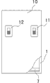
Fig. 2 is the shell mechanism schematic diagram that the utility model is provided with control element.
Fig. 3 is the local structure for amplifying schematic diagram in the utility model air duct end.
The specific embodiment
Shown in accompanying drawing 1,2: this feed arrangement comprises frame 1, be arranged on the trapezoidal hopper 2 of frame 1 upper end, be arranged on the pusher auger 3 of discharge port ends below trapezoidal hopper 2, the reducing motor 4 that connects pusher auger 3 one ends, the drainage conduit 5 that is connected to pusher auger 3 other ends, the blower fan 6 that is arranged on frame 1 bottom, connecting fan 6 be with the air duct 8 of outlet air end 7, described outlet air end 7 is the tubular structures that an end blocks, arrange perpendicular to air duct 8, on it with a plurality of exhaust vents 9.
Shown in accompanying drawing 3: the periphery of described frame 1 is provided with housing 10, is provided with the time switch 11 and the time switch 12 of controlling reducing motor 4 of control blower fan 6 in a side of housing 10.
Operation principle:
During use, the stalk particle material is put into trapezoidal hopper 2, set the start-up time of reducing motor 4 and blower fan 6 according to actual conditions, reducing motor 4 starts will drive 3 rotations of pusher auger, and the stalk particle material is advanced to drainage conduit 5 through pusher auger 3 and enters combustion furnace 13; Blower fan 6 starts, and wind will be entered outlet air end 7 and be entered combustion furnace 13 bottom oxygen-supplying combustion-supportings through a plurality of exhaust vents 9 on it by air duct 8.
Claims (2)
1. stalk particle burning stove feed arrangement, it is characterized in that: this feed arrangement comprises frame (1), be arranged on the trapezoidal hopper (2) of frame (1) upper end, be arranged on the pusher auger (3) of the following discharge port end of trapezoidal hopper (2), the reducing motor (4) that connects pusher auger (3) one ends, be connected to the drainage conduit (5) of pusher auger (3) other end, be arranged on the blower fan (6) of frame (1) bottom, connecting fan (6) is with the air duct (8) of outlet air end (7), described outlet air end (7) is a tubular structure that an end blocks, arrange perpendicular to air duct (8), on it with a plurality of exhaust vents (9).
2. a kind of stalk particle burning stove feed arrangement according to claim 1, it is characterized in that: the periphery of described frame (1) is provided with housing (10), is provided with the time switch (11) of controlling blower fan (6) and the time switch (12) of control reducing motor (4) in a side of housing (10).
Priority Applications (1)
| Application Number | Priority Date | Filing Date | Title |
|---|---|---|---|
| CN 201320121553 CN203273927U (en) | 2013-03-18 | 2013-03-18 | Feeding device of straw particle combustion furnace |
Applications Claiming Priority (1)
| Application Number | Priority Date | Filing Date | Title |
|---|---|---|---|
| CN 201320121553 CN203273927U (en) | 2013-03-18 | 2013-03-18 | Feeding device of straw particle combustion furnace |
Publications (1)
| Publication Number | Publication Date |
|---|---|
| CN203273927U true CN203273927U (en) | 2013-11-06 |
Family
ID=49504326
Family Applications (1)
| Application Number | Title | Priority Date | Filing Date |
|---|---|---|---|
| CN 201320121553 Expired - Fee Related CN203273927U (en) | 2013-03-18 | 2013-03-18 | Feeding device of straw particle combustion furnace |
Country Status (1)
| Country | Link |
|---|---|
| CN (1) | CN203273927U (en) |
Cited By (3)
| Publication number | Priority date | Publication date | Assignee | Title |
|---|---|---|---|---|
| CN105249847A (en) * | 2015-11-07 | 2016-01-20 | 平湖伟峰科技有限责任公司 | Feeding device |
| CN109006073A (en) * | 2018-08-08 | 2018-12-18 | 郑州天惠能源科技有限公司 | Greenhouse biomass combustion furnace |
| CN113203092A (en) * | 2021-04-21 | 2021-08-03 | 武汉理工大学 | Biomass pretreatment feeding device based on circulating fluidized bed |
-
2013
- 2013-03-18 CN CN 201320121553 patent/CN203273927U/en not_active Expired - Fee Related
Cited By (4)
| Publication number | Priority date | Publication date | Assignee | Title |
|---|---|---|---|---|
| CN105249847A (en) * | 2015-11-07 | 2016-01-20 | 平湖伟峰科技有限责任公司 | Feeding device |
| CN105249847B (en) * | 2015-11-07 | 2018-04-06 | 平湖伟峰科技有限责任公司 | Feed device |
| CN109006073A (en) * | 2018-08-08 | 2018-12-18 | 郑州天惠能源科技有限公司 | Greenhouse biomass combustion furnace |
| CN113203092A (en) * | 2021-04-21 | 2021-08-03 | 武汉理工大学 | Biomass pretreatment feeding device based on circulating fluidized bed |
Similar Documents
| Publication | Publication Date | Title |
|---|---|---|
| CN203657201U (en) | Biomass fuel hot blast stove | |
| CN103438434B (en) | Bio-particle fuel burner | |
| CN103697461A (en) | Biomass fuel combustion device | |
| CN201875688U (en) | Pot type bottom-feeding biomass particle burner | |
| CN203273927U (en) | Feeding device of straw particle combustion furnace | |
| CN201992694U (en) | Program-controlled biomass high-efficiency combustion furnace | |
| CN105003910A (en) | Centralized heat supply device adopting biomass briquette as raw materials | |
| CN102022722B (en) | Pot type bottom-feeding biomass particle burner | |
| CN205619252U (en) | Biomass burning machine | |
| CN202955861U (en) | Energy-saving and environmental-friendly type curing barn heat supply burner | |
| CN112050192A (en) | Energy-concerving and environment-protective type biomass energy granule is with firing burning furnace | |
| CN207316892U (en) | A kind of skewered grate structure | |
| CN102116489B (en) | Stove capable of preventing slagging | |
| CN201903068U (en) | Slag-bonding prevention furnace | |
| CN102121710B (en) | Anti-slagging stove | |
| CN104864418A (en) | Decoking combustion-supporting type biomass straw particle burning furnace and stove set | |
| CN109578963B (en) | Biological new energy combustion system adopting biomass fuel combustion | |
| CN209688896U (en) | Household portable picnic biomass gasification stove | |
| CN201903070U (en) | Anticlogging stove | |
| CN206247314U (en) | A kind of biomass boiler | |
| CN103032957A (en) | Biomass gasification hot air furnace | |
| CN201697173U (en) | Energy-saving environmental-protecting biomass mild gasification furnace | |
| CN205690441U (en) | Biomass heat supply heating stove | |
| CN201034323Y (en) | Plant powder type fuel boiler | |
| CN205065694U (en) | Full -automatic integrated biomass combustion furnace |
Legal Events
| Date | Code | Title | Description |
|---|---|---|---|
| C14 | Grant of patent or utility model | ||
| GR01 | Patent grant | ||
| CF01 | Termination of patent right due to non-payment of annual fee | ||
| CF01 | Termination of patent right due to non-payment of annual fee |
Granted publication date: 20131106 Termination date: 20180318 |