CN203205362U - Connecting structure of pedestal and handle of circuit breaker - Google Patents
Connecting structure of pedestal and handle of circuit breaker Download PDFInfo
- Publication number
- CN203205362U CN203205362U CN 201320251310 CN201320251310U CN203205362U CN 203205362 U CN203205362 U CN 203205362U CN 201320251310 CN201320251310 CN 201320251310 CN 201320251310 U CN201320251310 U CN 201320251310U CN 203205362 U CN203205362 U CN 203205362U
- Authority
- CN
- China
- Prior art keywords
- handle
- pedestal
- circuit breaker
- dop
- connecting structure
- Prior art date
- Legal status (The legal status is an assumption and is not a legal conclusion. Google has not performed a legal analysis and makes no representation as to the accuracy of the status listed.)
- Expired - Fee Related
Links
Images

Landscapes
- Breakers (AREA)
Abstract
The utility model relates to a circuit breaker, particularly to the connecting structure of a pedestal and a handle of the circuit breaker. The connecting structure of the pedestal and the handle of the circuit breaker comprises the pedestal and the handle, the pedestal is transversely provided with clamping heads, and the handle is transversely provided with a clamping groove matched with the clamping heads. According to the connecting structure of the pedestal and the handle of the circuit breaker, skillfully, the pedestal is transversely provided with the clamping heads, the handle is transversely provided with the clamping groove matched with the clamping heads, and since the clamping heads and the clamping groove are transversely arranged, the handle is prevented from being disengaged from the pedestal when the handle is shifted.
Description
Technical field
The utility model relates to a kind of circuit breaker, relates in particular to a kind of syndeton of pedestal and handle of circuit breaker.
Background technology
At present, in the general circuit breaker, by being connected of handle and pedestal, stirring handle drive pedestal and come operating breaker.Vertical direction is provided with dop on the existing pedestal, on the handle vertical direction be provided with dop be complementary draw-in groove; During assembling, with the draw-in groove on the handle and the dop clamping on the pedestal.Such structure about when stirring handle, handle breaks away from pedestal easily.
Summary of the invention
The purpose of this utility model is exactly the defective that exists at prior art, provides a kind of simple in structure, and when operation, handle is not easy to break away from the pedestal of circuit breaker of pedestal and the syndeton of handle.
The utility model is achieved through the following technical solutions: a kind of pedestal of circuit breaker and the syndeton of handle, comprise pedestal and handle, and laterally be provided with dop on the described pedestal, laterally be provided with the draw-in groove that is complementary with described dop on the described handle.
As preferably, above-mentioned dop is 2, and it is symmetrically distributed on the described pedestal.
The utility model is horizontally arranged with dop at pedestal cleverly, laterally is provided with the draw-in groove that is complementary with dop on handle, because dop and draw-in groove are horizontally set, has avoided when stirring handle, and handle breaks away from pedestal.
Description of drawings
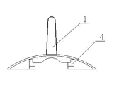
Fig. 1 is the structural representation of the utility model embodiment.
Fig. 2 is the structural representation of handle 1 among Fig. 1.
Embodiment
1-2 by reference to the accompanying drawings, the utility model will be further described: a kind of pedestal of circuit breaker and the syndeton of handle comprise pedestal 2 and handle 1.Laterally be provided with draw-in groove 4 on the handle 1.
Laterally be provided with the dop 3 that is complementary with described draw-in groove 4 on the described pedestal 2, dop 3 is 2, and it is symmetrically distributed on the described pedestal 2, has further strengthened the steadiness between pedestal 2 and the handle 1.
When assembling, only need dop 3 laterally inserted draw-in grooves 4 are namely finished installation, structure is simple relatively.
Claims (2)
1. the syndeton of the pedestal of a circuit breaker and handle comprises pedestal and handle, it is characterized in that, laterally is provided with dop on the described pedestal, laterally is provided with the draw-in groove that is complementary with described dop on the described handle.
2. the syndeton of a kind of circuit breaker pedestal according to claim 1 and handle is characterized in that, described dop is 2, and it is symmetrically distributed on the described pedestal.
Priority Applications (1)
| Application Number | Priority Date | Filing Date | Title |
|---|---|---|---|
| CN 201320251310 CN203205362U (en) | 2013-05-10 | 2013-05-10 | Connecting structure of pedestal and handle of circuit breaker |
Applications Claiming Priority (1)
| Application Number | Priority Date | Filing Date | Title |
|---|---|---|---|
| CN 201320251310 CN203205362U (en) | 2013-05-10 | 2013-05-10 | Connecting structure of pedestal and handle of circuit breaker |
Publications (1)
| Publication Number | Publication Date |
|---|---|
| CN203205362U true CN203205362U (en) | 2013-09-18 |
Family
ID=49149443
Family Applications (1)
| Application Number | Title | Priority Date | Filing Date |
|---|---|---|---|
| CN 201320251310 Expired - Fee Related CN203205362U (en) | 2013-05-10 | 2013-05-10 | Connecting structure of pedestal and handle of circuit breaker |
Country Status (1)
| Country | Link |
|---|---|
| CN (1) | CN203205362U (en) |
Cited By (1)
| Publication number | Priority date | Publication date | Assignee | Title |
|---|---|---|---|---|
| CN113119818A (en) * | 2021-04-28 | 2021-07-16 | 上海工程技术大学 | Child safety seat for vehicle |
-
2013
- 2013-05-10 CN CN 201320251310 patent/CN203205362U/en not_active Expired - Fee Related
Cited By (1)
| Publication number | Priority date | Publication date | Assignee | Title |
|---|---|---|---|---|
| CN113119818A (en) * | 2021-04-28 | 2021-07-16 | 上海工程技术大学 | Child safety seat for vehicle |
Similar Documents
| Publication | Publication Date | Title |
|---|---|---|
| CN203205362U (en) | Connecting structure of pedestal and handle of circuit breaker | |
| CN204732549U (en) | A kind of quick-connect terminal platform | |
| CN204615751U (en) | A kind of diode anti-reverse mounting structure | |
| CN102436882A (en) | Resistor with wavelike resistor discs | |
| CN203979281U (en) | mechanical chain connection device | |
| CN202034721U (en) | Movable slot | |
| CN203321983U (en) | Rod body connecting tool for insulating rod | |
| CN203300562U (en) | Electromagnetic relay convenient for routing | |
| CN203289207U (en) | Bar-shaped stator core | |
| CN201966033U (en) | Pin bolt-free transformer iron core drawplate | |
| CN202332595U (en) | Connecting structure of terminal in switch and casing | |
| CN202076094U (en) | Fixing device for led-out copper bars of transformer | |
| CN204696315U (en) | A kind of fixed dam syndeton | |
| CN204408780U (en) | A kind of audio frequency and video switching panel | |
| CN203103569U (en) | Circular terminal with fixing function | |
| CN206116798U (en) | Plug with pilot lamp | |
| CN204407576U (en) | A kind of high-performance electric connector | |
| CN204591734U (en) | A kind of bull micro fan | |
| CN205230967U (en) | Control protection switch | |
| CN204793812U (en) | A combined electrical apparatus for miniaturizing cubical switchboard | |
| CN202038270U (en) | Shaft sleeve of windscreen wiper | |
| CN203967430U (en) | A kind of terminal supporting | |
| CN202444341U (en) | Salient synchronous motor magnetic pole | |
| CN202172158U (en) | Eight-wire plug sheath of automobile electrical appliance | |
| CN204071836U (en) | A kind of electric machine for mixer |
Legal Events
| Date | Code | Title | Description |
|---|---|---|---|
| C14 | Grant of patent or utility model | ||
| GR01 | Patent grant | ||
| CF01 | Termination of patent right due to non-payment of annual fee |
Granted publication date: 20130918 Termination date: 20160510 |
|
| CF01 | Termination of patent right due to non-payment of annual fee |