CN203196798U - Solid state grease atomizing and spraying device - Google Patents
Solid state grease atomizing and spraying device Download PDFInfo
- Publication number
- CN203196798U CN203196798U CN 201320143441 CN201320143441U CN203196798U CN 203196798 U CN203196798 U CN 203196798U CN 201320143441 CN201320143441 CN 201320143441 CN 201320143441 U CN201320143441 U CN 201320143441U CN 203196798 U CN203196798 U CN 203196798U
- Authority
- CN
- China
- Prior art keywords
- oil
- oil tank
- grease
- spraying device
- cavity
- Prior art date
- Legal status (The legal status is an assumption and is not a legal conclusion. Google has not performed a legal analysis and makes no representation as to the accuracy of the status listed.)
- Expired - Fee Related
Links
Images
Abstract
The utility model discloses a solid state grease atomizing and spraying device which comprises an oil tank. The oil tank comprises an oil tank body provided with an upper opening and an oil tank upper cover tightly covering the upper opening. The oil tank body and the oil tank upper cover form an inner cavity of the oil tank, and a piston divides the cavity into an air cavity and an oil cavity. The air cavity is provided with an air inlet, and the oil cavity is provided with an oil outlet. The air inlet is formed in the oil tank upper cover, and the oil outlet is connected with a high-pressure spray gun arranged outside the oil tank through a pipeline. When the solid state grease atomizing and spraying device works, solid state grease is filled into the oil cavity, high-pressure gas is filled from the air inlet so as to press the piston downwards, the solid state grease is dispersed and divided to be in the semi-atomization state and is discharged from the oil outlet to enter the high-pressure spray gun, and secondary atomization is performed so as to spray oil mist. According to the spraying effect, grease can be evenly coated on a workpiece, waste of the grease is small, and multi-angle spraying can be achieved by adjusting the workpiece or the direction of the high-pressure spray gun. The solid state grease atomizing and spraying device is widely used in workpiece spraying work of the solid grease.
Description
Technical field
The utility model relates to a kind of grease spraying device of using on a kind of machinery production line.
Background technology
Solid grease is all can use in a lot of industries, and it is bringing into play the important effects such as lubricated, waterproof, anticorrosion, sealing at various parts.The utilization of the solid grease of using at present, all be the semi-automatic work of manual oiling or the mode of utilizing machinery, like this in real work, tend to carelessness owing to the restriction of operating environment or operating personnel produce a large amount of wastes, need the spraying position not evenly, have the dead angle spraying less than etc. situation.
The utility model content
The technical problems to be solved in the utility model is: a kind of solid grease atomizing spraying device is provided, and 1. it can solve, how solid grease be atomized; 2., how to allow mist of oil evenly, exactly the ejection technical problem.
The solution that the utility model solves its technical problem is:
Solid grease atomizing spraying device, comprise oil tank, oil tank comprises the oil tank body with upper shed and the oil tank loam cake that covers tightly described upper shed, the oil tank body forms the internal cavities of oil tank with the oil tank loam cake, piston is separated into air cavity and two parts of oil pocket with this cavity, described air cavity is provided with air inlet, and described oil pocket is provided with oil-out; Described air inlet is opened on the oil tank and covers, and oil-out is connected with high-pressure spray gun outside being located at oil tank by pipeline.
More efficient convenient in order to allow device use, thus can for how covering tightly the oil tank loam cake, how knowing in time that solid grease exhausts aspects such as replenishing grease and optimizes structure, and these will be mentioned in the embodiment of this specification.
The beneficial effects of the utility model are: during work, in oil pocket, inject solid grease first, then pass into gases at high pressure from air inlet, pushing piston presses down, under high pressure solid grease be dispersed be divided into half the atomizing shape discharge from oil-out, enter into high-pressure spray gun, then sprayed by the high-pressure spray gun secondary-atomizing, formation uniform particles, the spraying mist of oil that coverage is large.Such spray effect so that the workpiece oiling evenly, has fully reduced the grease waste, and can be realized by the orientation of adjusting workpiece or high-pressure spray gun the multi-angle spraying, and is simple and convenient.The utility model can be widely used in the Workpiece painting operation of solid grease.
Description of drawings
In order to be illustrated more clearly in the technical scheme among the utility model embodiment, the accompanying drawing of required use was done simple declaration during the below will describe embodiment.Obviously, described accompanying drawing is a part of embodiment of the present utility model, rather than whole embodiment, and those skilled in the art can also obtain other designs and accompanying drawing according to these accompanying drawings under the prerequisite of not paying creative work.
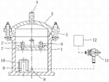
Fig. 1 is structural representation of the present utility model, and oil tank and internals thereof are in analyses and observe state, and the dotted line among the figure represents the pipeline annexation.
The specific embodiment
Be clearly and completely described below with reference to embodiment and the accompanying drawing technique effect to design of the present utility model, concrete structure and generation, to understand fully the purpose of this utility model, feature and effect.Obviously; described embodiment is a part of embodiment of the present utility model, rather than whole embodiment, based on embodiment of the present utility model; other embodiment that those skilled in the art obtains under the prerequisite of not paying creative work all belong to the scope that the utility model is protected.In addition, all connection/annexations of mentioning in the literary composition are not to refer to that singly member directly joins, and refer to and can connect auxiliary by adding or reducing according to the implementation situation, form more excellent draw bail.
With reference to Fig. 1, solid grease atomizing spraying device, comprise oil tank, oil tank comprises the oil tank body 1 with upper shed and the oil tank loam cake 3 that covers tightly described upper shed, oil tank body 1 forms the internal cavities of oil tank with oil tank loam cake 3, piston 7 is separated into air cavity and two parts of oil pocket with this cavity, and described air cavity is provided with air inlet 4, and described oil pocket is provided with oil-out 8; Described air inlet 4 is opened on the oil tank loam cake 3, and oil-out 8 is connected with high-pressure spray gun outside being located at oil tank by pipeline.In addition, in order to guarantee air-tightness, be provided with the sealing ring hermetically-sealed construction at the interface position of oil tank loam cake 3 and oil tank body 1.
Embodiment 1: the using method of said apparatus, need to open first oil tank loam cake 3, extract piston 7, insert solid grease toward oil pocket, then piston 7 is put back in the cavity, the oil tank loam cake 3 that closes is again sealed, and presses down from air inlet 4 ventilation pushing pistons 7 afterwards, the atomizing of compressing grease is finally penetrated from high-pressure spray gun.For convenient mounting or dismounting oil tank loam cake 3, can utilize dismountable tank cap tamponade 5 that oil tank loam cake 3 is locked in the upper shed of oil tank body 1, in the time of need to opening loam cake, as long as tank cap tamponade 5 is unloaded.In addition, can be convenient to carry the handle of putting in piston 7 settings.
Embodiment 2: take embodiment 1 as the basis, be provided with grease inlet 2 and oil pocket exhaust outlet 6 at piston 7.Like this, then need not extract piston 7, as long as utilize the grease injection device of peripheral hardware, then can in oil pocket, replenish solid grease easily.Oil pocket exhaust outlet 6 can avoid because of air pressure gradually the excessive grease that causes inject and have some setbacks.Certainly, in oiling, oil-out 8 seals, and when piston 7 pressed down the atomizing grease, oil-out 8 was opened, and 6 of grease inlet 2 and oil pocket exhaust outlets all seal.
Embodiment 3: take embodiment 1 or 2 as the basis, described oil-out 8 is located on the sidewall of oil tank body 1, and the position of oil-out 8 is near the diapire of oil tank body 1.Be provided with sensor shield 10 and the metal sensor 9 that is arranged in sensor shield 10 in the described oil pocket.Below the position of oil-out 8 is located at as far as possible, can take full advantage of as much as possible the solid grease in the oil pocket.Piston 7 constantly presses down, constantly discharge from oil-out 8 after the solid grease atomizing, when the similar diapire near oil tank bodies 1 of piston 7, solid grease also almost consumes and makes a gift of to the greatest extent, this moment, piston 7 will be pressed onto sensor shield 10, metal sensor 9 is sensed piston, then can send the oil starvation signal to electric-control system, allows machine or workman in time replenish grease.
Embodiment 4: take embodiment 1 as the basis, high-pressure spray gun can be made into such shape and structure: described high-pressure spray gun comprises spray gun body 11, these spray gun body 11 integral body are the threeway member of " T " font, have high pressure grease entrance, pressurized gas inlet and nozzle, described high pressure grease entrance is connected with oil-out 8 pipelines, pressurized gas inlet is connected with high-pressure air source 12 pipelines, and pressurized gas inlet and nozzle are coaxial.Because the flow at high speed of high pressure draught is arranged, and the shape grease that partly atomizes that enters into spray gun body 11 inside from the high pressure grease entrance will be dispelled immediately, secondary-atomizing becomes the mist of oil that oil droplet is even, coverage is large, and goes out from nozzle ejection.The connecting pipe of high pressure grease entrance and oil-out 8 can be flexible pipe or hard tube, if during flexible pipe, can utilize manipulator even artificial hand-held mode to adjust the spraying orientation angles; If hard tube, then can be by adjust the spray-coating surface of workpiece such as modes such as rotations.High-pressure spray gun is provided with oil controller, and adjusting device can be regulated the spray volume of mist of oil, enables with the demand of actual spraying work adaptive.During work, the air pressure of the gas that enters from pressurized gas inlet should be 3 times of pressure of the high pressure grease that enters from the high pressure grease entrance.
Above better embodiment of the present utility model is specified, but the invention is not limited to described embodiment, those of ordinary skill in the art also can make all equivalent modifications or replacement under the prerequisite of the utility model spirit, the modification that these are equal to or replacement all are included in the application's claim limited range.
Claims (6)
1. solid grease atomizing spraying device, it is characterized in that: comprise oil tank, oil tank comprises the oil tank body (1) with upper shed and the oil tank loam cake (3) that covers tightly described upper shed, oil tank body (1) forms the internal cavities of oil tank with oil tank loam cake (3), piston (7) is separated into air cavity and two parts of oil pocket with this cavity, described air cavity is provided with air inlet (4), and described oil pocket is provided with oil-out (8); Described air inlet (4) is opened on the oil tank loam cake (3), and oil-out (8) is connected with high-pressure spray gun outside being located at oil tank by pipeline.
2. solid grease atomizing spraying device according to claim 1, it is characterized in that: described oil tank loam cake (3) is locked in the upper shed of oil tank body (1) by dismountable tank cap tamponade (5).
3. solid grease atomizing spraying device according to claim 1, it is characterized in that: piston (7) is provided with grease inlet (2) and oil pocket exhaust outlet (6).
4. solid grease atomizing spraying device according to claim 1, it is characterized in that: described oil-out (8) is located on the sidewall of oil tank body (1), and the position of oil-out (8) is near the diapire of oil tank body (1).
5. solid grease atomizing spraying device according to claim 1 is characterized in that: be provided with sensor shield (10) in the described oil pocket and be arranged in the metal sensor (9) of sensor shield (10).
6. solid grease atomizing spraying device according to claim 1, it is characterized in that: described high-pressure spray gun comprises spray gun body (11), this spray gun body (11) integral body is the threeway member of " T " font, have high pressure grease entrance, pressurized gas inlet and nozzle, described high pressure grease entrance is connected with oil-out (8) pipeline, pressurized gas inlet is connected with high-pressure air source (12) pipeline, and pressurized gas inlet and nozzle are coaxial.
Priority Applications (1)
| Application Number | Priority Date | Filing Date | Title |
|---|---|---|---|
| CN 201320143441 CN203196798U (en) | 2013-03-26 | 2013-03-26 | Solid state grease atomizing and spraying device |
Applications Claiming Priority (1)
| Application Number | Priority Date | Filing Date | Title |
|---|---|---|---|
| CN 201320143441 CN203196798U (en) | 2013-03-26 | 2013-03-26 | Solid state grease atomizing and spraying device |
Publications (1)
| Publication Number | Publication Date |
|---|---|
| CN203196798U true CN203196798U (en) | 2013-09-18 |
Family
ID=49140939
Family Applications (1)
| Application Number | Title | Priority Date | Filing Date |
|---|---|---|---|
| CN 201320143441 Expired - Fee Related CN203196798U (en) | 2013-03-26 | 2013-03-26 | Solid state grease atomizing and spraying device |
Country Status (1)
| Country | Link |
|---|---|
| CN (1) | CN203196798U (en) |
Cited By (2)
| Publication number | Priority date | Publication date | Assignee | Title |
|---|---|---|---|---|
| CN109013090A (en) * | 2018-09-18 | 2018-12-18 | 江苏金泰祥内外门业有限公司 | A kind of glue coating case |
| CN109701774A (en) * | 2017-10-26 | 2019-05-03 | 昊瑞森(固安)能源科技有限公司 | Spray equipment and spraying method used in a kind of aluminium alloy inner container spinning process |
-
2013
- 2013-03-26 CN CN 201320143441 patent/CN203196798U/en not_active Expired - Fee Related
Cited By (3)
| Publication number | Priority date | Publication date | Assignee | Title |
|---|---|---|---|---|
| CN109701774A (en) * | 2017-10-26 | 2019-05-03 | 昊瑞森(固安)能源科技有限公司 | Spray equipment and spraying method used in a kind of aluminium alloy inner container spinning process |
| CN109701774B (en) * | 2017-10-26 | 2023-11-10 | 深圳昊海森氢能科技有限公司 | Spraying device and spraying method used in aluminum alloy liner spinning process |
| CN109013090A (en) * | 2018-09-18 | 2018-12-18 | 江苏金泰祥内外门业有限公司 | A kind of glue coating case |
Similar Documents
| Publication | Publication Date | Title |
|---|---|---|
| CN204429532U (en) | A kind of powder-coating spraying gun | |
| CN203196798U (en) | Solid state grease atomizing and spraying device | |
| CN204034477U (en) | Wind send depositing dust spraying machine | |
| CN203615036U (en) | Grease tank and lubricating system with same | |
| CN204816972U (en) | Insulating blackwash sprayer | |
| CN205887277U (en) | Pneumatic reciprocating motion type can spout injection apparatus who covers multiple compound anticorrosive paint | |
| CN208245003U (en) | Multi-functional fog gun machine | |
| CN202162102U (en) | Sedimentation prevention type spraying device | |
| CN205701182U (en) | Granule thick liquid sprayer | |
| CN204107719U (en) | Bulky grain blackwash sprayer | |
| CN205118624U (en) | Contactless automatic canning filling machine of bearing grease | |
| CN207709248U (en) | A kind of gear oiling machine | |
| CN202387612U (en) | Air pressure type paint-spraying device | |
| CN207463528U (en) | Ball blast spray painting all-in-one machine | |
| CN208750389U (en) | A kind of pump nozzle of dust-protection type lubricating oil grease gun | |
| CN209271713U (en) | Anti-explosion box body spray equipment | |
| CN204070263U (en) | Sprayer is explosion-proof stirs liquid single tube | |
| CN206793966U (en) | A kind of modified form Spray painting tool applied to antiseptic wearable coat | |
| CN200996536Y (en) | Pneumatic grease pump | |
| CN206319931U (en) | A kind of gas lubrication device | |
| CN207287839U (en) | A kind of small-sized automatic spray apparatus | |
| CN206924942U (en) | A kind of building water-proof spray robot paint can | |
| CN204672475U (en) | Novel gravity spray gun for paint | |
| CN213000670U (en) | High stability leak protection spray gun | |
| CN207385747U (en) | Leakage-proof spray gun |
Legal Events
| Date | Code | Title | Description |
|---|---|---|---|
| C14 | Grant of patent or utility model | ||
| GR01 | Patent grant | ||
| CF01 | Termination of patent right due to non-payment of annual fee |
Granted publication date: 20130918 Termination date: 20170326 |
|
| CF01 | Termination of patent right due to non-payment of annual fee |