CN203166540U - Combined type high-voltage direct current transmission system - Google Patents
Combined type high-voltage direct current transmission system Download PDFInfo
- Publication number
- CN203166540U CN203166540U CN 201320030429 CN201320030429U CN203166540U CN 203166540 U CN203166540 U CN 203166540U CN 201320030429 CN201320030429 CN 201320030429 CN 201320030429 U CN201320030429 U CN 201320030429U CN 203166540 U CN203166540 U CN 203166540U
- Authority
- CN
- China
- Prior art keywords
- anode
- power electronics
- negative terminal
- controlling power
- electronics device
- Prior art date
- Legal status (The legal status is an assumption and is not a legal conclusion. Google has not performed a legal analysis and makes no representation as to the accuracy of the status listed.)
- Expired - Lifetime
Links
Images


Classifications
-
- Y—GENERAL TAGGING OF NEW TECHNOLOGICAL DEVELOPMENTS; GENERAL TAGGING OF CROSS-SECTIONAL TECHNOLOGIES SPANNING OVER SEVERAL SECTIONS OF THE IPC; TECHNICAL SUBJECTS COVERED BY FORMER USPC CROSS-REFERENCE ART COLLECTIONS [XRACs] AND DIGESTS
- Y02—TECHNOLOGIES OR APPLICATIONS FOR MITIGATION OR ADAPTATION AGAINST CLIMATE CHANGE
- Y02E—REDUCTION OF GREENHOUSE GAS [GHG] EMISSIONS, RELATED TO ENERGY GENERATION, TRANSMISSION OR DISTRIBUTION
- Y02E60/00—Enabling technologies; Technologies with a potential or indirect contribution to GHG emissions mitigation
- Y02E60/60—Arrangements for transfer of electric power between AC networks or generators via a high voltage DC link [HVCD]
Landscapes
- Inverter Devices (AREA)
- Rectifiers (AREA)
Abstract
The utility model provides a combined type high-voltage direct current transmission system which comprises at least one rectification station, an inversion station and an overhead electric power transmission line. Both of the rectification station and the inversion station comprise positive electrodes and negative electrodes, a thyristor current converter is adopted in the rectification station, each of a positive electrode and a negative electrode of the thyristor current converter comprises at least one twelve-impulse thyristor current converter, a voltage source current converter capable of disposing direct current faults is adopted in the inversion station, and each of a positive electrode and a negative electrode of the voltage source current converter at least comprises two modularized multi-level current converters which are connected in series. Connection points of the positive and negative electrodes of each station are connected with a grounding electrode or a station inner ground network according to a double electrode ground return wire operation mode or a single ground return wire operation mode or a single electrode metal return wire operation mode of the direct current transmission system. The rectification station is connected with the inversion station through the overhead electric power transmission line. The combined type high-voltage direct current transmission system is characterized in that a commutation failure of the inversion station in the direct current transmission system can be prevented; the combined type high-voltage direct current transmission system is flexible in operation mode, high in reliability and reduced in project cost; moreover, the advantages of the thyristor current converter and the voltage source current are integrated; and the combined type high-voltage direct current transmission system is capable of disposing direct current side faults.
Description
Technical field
The utility model is a kind of compound HVDC (High Voltage Direct Current) transmission system that can handle the DC side fault, particularly a kind of converting plant that relates to adopts thyristor converter device, Inverter Station to adopt the HVDC (High Voltage Direct Current) transmission system of the many level modularization voltage source converter with direct current troubleshooting capability, belongs to the high-voltage dc transmission electrical domain.
Background technology
Converting plant and Inverter Station all adopt the HVDC (High Voltage Direct Current) transmission system of thyristor converter device to have that loss is little, cost is relatively low, the reliability advantages of higher.But commutation failure takes place during thyristor converter device inverter operation easily, concentrate the feed-in electrical network for many times direct currents, fault in ac transmission system may cause a plurality of current conversion stations commutation failure simultaneously, causes enormous impact to electrical network, has a strong impact on the safe and stable operation of system.
For adopting the thyristor converter device that the multiterminal HVDC transmission system of a plurality of Inverter Station is arranged, during an Inverter Station generation commutation failure, other stream electric current of respectively standing erectly will pour in this station, make this station produce very big transient current, may cause this station equipment to damage, this has limited the application of the multiterminal HVDC transmission system that a plurality of Inverter Station are arranged.
Voltage source converter adopts all-controlling power electronics device, fundamentally eliminates commutation failure.Flexible DC power transmission system based on voltage source converter had had significant progress in the last few years, be incorporated into the power networks at new forms of energy, interconnected with weak pattern system, obtained successful application to fields such as passive network and island load power supplies, shown than the better performance of DC transmission system that adopts the thyristor converter device, had a good application prospect.But the voltage source converter of equal electric pressure and capacity is high more a lot of than the investment of thyristor converter device.
The voltage source converter topology that is used for the flexible DC power transmission system mainly comprises two kinds: switching mode (Switch type) and controllable voltage source (Controllable voltage source type).The switching mode topology adopts two level or three level structures, and brachium pontis is connected by a plurality of all-controlling power electronics devices, and ABB AB is applied to a plurality of engineerings with this topology.There is devices switch frequency height in the switching mode topology, loss is big, dynamic voltage balancing is difficult, harmonic wave is big, electromagnetic interference is big, capacity promotes difficulty, the shortcomings such as high pass filter of needs configuration one constant volume.Controllable voltage source topology adopts the submodule cascade structure, to device trigger consistency, dynamic voltage balancing require low, favorable expandability, the transmission voltage waveform is good, switching frequency is low, running wastage is low, the alternating current-direct current side does not all need to dispose filter.Put into operation at present or mainly adopted half H bridge construction submodule in the flexible DC power transmission system that builds based on modularization multi-level converter.Voltage source converter topology based on two level, three level, half H bridge submodule does not possess the direct current troubleshooting capability, when DC side is short-circuited fault, constitute uncontrollable commutating circuit with the all-controlling power electronics device diode connected in parallel, can not adopt the DC side fault rebooting method in the thyristor converter device HVDC (High Voltage Direct Current) transmission system, can only carry out troubleshooting by tripping interchange side circuit breaker, response speed is slower, therefore be only applicable to the low cable line of failure rate, be not suitable for easily taking place the power overhead network of temporary fault.
Summary of the invention
The purpose of this utility model is to consider the problems referred to above and a kind of commutation failure of can not only eliminating is provided, and reduced the compound HVDC (High Voltage Direct Current) transmission system that can handle the DC side fault of project cost.The utility model combines the advantage of thyristor converter device and voltage source converter, it is a kind of compound HVDC (High Voltage Direct Current) transmission system that can handle the DC side fault, can finish system restart rapidly, operational mode is flexible, the reliability height, be specially adapted to concentrate the feed-in electrical network by remote overhead transmission line to many times direct currents, also be applicable to the multiterminal HVDC transmission system with two above Inverter Station.
The technical solution of the utility model is: compound HVDC (High Voltage Direct Current) transmission system of the present utility model, include at least one converting plant, an Inverter Station and built on stilts electric power transmission line, converting plant and Inverter Station all comprise positive pole and negative pole, wherein converting plant adopts the thyristor converter device, and the positive pole of thyristor converter device and negative pole all comprise one 12 pulsation thyristor converter device at least; Inverter Station adopts the voltage source converter with direct current troubleshooting capability, and the positive pole of voltage source converter and negative pole all comprise the modularization multi-level converter of two series connection at least; Each both positive and negative polarity tie point of standing is in bipolar, the big earthed return of one pole according to DC transmission system or one pole metallic return operational mode is connected with earth mat in earth electrode or the station, links to each other by making somebody a mere figurehead electric power transmission line between converting plant and the Inverter Station.
Above-mentioned converting plant and Inverter Station all dispose smoothing reactor, converting plant every extremely all configuring direct current filter and alternating current filter, every DC filter and the alternating current filter of extremely all not disposing of Inverter Station.
12 set pulsation thyristor converter devices of the positive pole of above-mentioned thyristor converter device and negative pole include six fluctuation bridges and reach six fluctuation bridges down, last six fluctuation bridges connect transformer Y side with a Y0/Y and are connected, six fluctuation bridges are connected with a Y0/ △ connection transformer △ side down, or last six fluctuation bridges of 12 pulsation thyristor converter devices reach down, and six fluctuation bridges are connected respectively with the △ side with the Y side that a Y0/Y/ △ connects transformer.
The set voltage source converter of above-mentioned Inverter Station is three-phase six brachium pontis structures, and each brachium pontis is made up of a reactor and several change of current modules, and several change of current module series connection back one sides connect the corresponding phase port of transformer △ side by reactor with Y0/ △ and connect.
Above-mentioned compound HVDC (High Voltage Direct Current) transmission system adopts complete dipolar configuration, and namely anodal, negative pole all can adopt one pole the earth or one pole metallic return operational mode independent operating.
Change of current module in the set voltage source converter of above-mentioned Inverter Station adopts the full-bridge submodule, or clamper Shuangzi module, or full-bridge submodule in parallel, or clamper two-in-parallel submodule.
The utility model combines the advantage of thyristor converter device and voltage source converter, Inverter Station adopts the voltage source converter with direct current troubleshooting capability to eliminate the commutation failure of Inverter Station, converting plant adopts the thyristor converter device can reduce project cost, adopt complete dipolar configuration to make that operational mode is flexible, reliability is high, be specially adapted to concentrate the feed-in electrical network by remote overhead transmission line to many times direct currents, also be applicable to the multiterminal HVDC transmission system with two above Inverter Station.Compound HVDC (High Voltage Direct Current) transmission system of the present utility model is reasonable in design, convenient and practical, both can be used for newly-built DC transmission engineering, also can be used for building the transformation of DC transmission engineering, has broad application prospects.
Description of drawings
Below in conjunction with the drawings and specific embodiments the utility model patent is further described.
Fig. 1 is the structural representation of compound HVDC (High Voltage Direct Current) transmission system of the present utility model.
Fig. 2 is the structural representation of 12 pulsation thyristor converter devices of the utility model converting plant employing.
Fig. 3 is the structural representation of the modularization multi-level converter of the utility model Inverter Station employing.
Fig. 4 is the structural representation of the full-bridge submodule of the utility model employing.
Fig. 5 is the structural representation of the clamper Shuangzi module of the utility model employing.
Fig. 6 is the structural representation of the full-bridge submodule in parallel of the utility model employing.
Fig. 7 is the structural representation of the clamper Shuangzi module in parallel of the utility model employing.
Embodiment
Embodiment:
A kind of compound HVDC (High Voltage Direct Current) transmission system of the present utility model, compound HVDC (High Voltage Direct Current) transmission system of the present utility model, include at least one converting plant, an Inverter Station and built on stilts electric power transmission line, converting plant and Inverter Station all comprise positive pole and negative pole, wherein converting plant adopts the thyristor converter device, and the positive pole of thyristor converter device and negative pole all comprise one 12 pulsation thyristor converter device at least; Inverter Station adopts the voltage source converter with direct current troubleshooting capability, and the positive pole of voltage source converter and negative pole all comprise the modularization multi-level converter of two series connection at least; Each both positive and negative polarity tie point of standing is in bipolar, the big earthed return of one pole according to DC transmission system or one pole metallic return operational mode is connected with earth mat in earth electrode or the station, links to each other by making somebody a mere figurehead electric power transmission line between converting plant and the Inverter Station.
Above-mentioned converting plant and Inverter Station all dispose smoothing reactor, converting plant every extremely all configuring direct current filter and alternating current filter, every DC filter and the alternating current filter of extremely all not disposing of Inverter Station.
12 set pulsation thyristor converter devices of the positive pole of above-mentioned thyristor converter device and negative pole include six fluctuation bridges and reach six fluctuation bridges down, last six fluctuation bridges connect transformer Y side with a Y0/Y and are connected, six fluctuation bridges are connected with a Y0/ △ connection transformer △ side down, or last six fluctuation bridges of 12 pulsation thyristor converter devices reach down, and six fluctuation bridges are connected respectively with the △ side with the Y side that a Y0/Y/ △ connects transformer.
The set voltage source converter of above-mentioned Inverter Station is three-phase six brachium pontis structures, and each brachium pontis is made up of a reactor and several change of current modules, and several change of current module series connection back one sides connect the corresponding phase port of transformer △ side by reactor with Y0/ △ and connect.
Above-mentioned compound HVDC (High Voltage Direct Current) transmission system adopts complete dipolar configuration, and namely anodal, negative pole all can adopt one pole the earth or one pole metallic return operational mode independent operating.
Change of current module in the set voltage source converter of above-mentioned Inverter Station adopts the full-bridge submodule, or clamper Shuangzi module, or full-bridge submodule in parallel, or clamper two-in-parallel submodule.
The structural representation that the utility model is applied to the both-end HVDC (High Voltage Direct Current) transmission system as shown in Figure 1, converting plant comprises positive pole and negative pole, and every Y0/Y that extremely mainly comprises connects transformer Ty, Y0/ △ connection transformer Td, 12 pulsation thyristor converter device R, smoothing reactor SRr, DC filter DCF, alternating current filter ACF; Y0/Y connects the Y side of transformer Ty, the △ side that Y0/ △ connects transformer Td is connected respectively with six fluctuation bridges up and down of 12 pulsation thyristor converter device R, and Y0/Y connects the Y0 side of transformer Ty, the Y0 side that Y0/ △ connects transformer Td is connected with sending end electrical network ac bus; It is in parallel with DC filter DCF after 12 pulsation thyristor converter device R connect with smoothing reactor SRr; Alternating current filter ACF is connected on the sending end electrical network ac bus.
In the present embodiment, Inverter Station comprises positive pole and negative pole, every two Y0/ △ connection transformer Td, two modularization multi-level converter VSC, smoothing reactor SRi of extremely mainly comprising; The △ side that Y0/ △ connects transformer Td is connected with modularization multi-level converter VSC, and the Y0 side is connected with receiving end electrical network ac bus; Connect with smoothing reactor in two modularization multi-level converter VSC series connection backs.In the present embodiment, be connected by overhead transmission line OHL between converting plant and Inverter Station homopolarity smoothing reactor.
Each both positive and negative polarity tie point of standing is in bipolar, the big earthed return of one pole according to DC transmission system or one pole metallic return operational mode is connected with earth mat in earth electrode or the station.
12 pulsation thyristor converter device R as shown in Figure 2, last six fluctuation bridges are that Y0/Y connection transformer Y side is connected with a mode of connection, six fluctuation bridges are connected for Y0/ △ connects transformer △ side with a mode of connection down, also can be that six fluctuation bridges are connected respectively with △ with the Y side of a Y0/Y/ △ about the 12 pulsation thyristor converter device R.
In the present embodiment, has the voltage source converter VSC of direct current troubleshooting capability as shown in Figure 3, be three-phase six brachium pontis structures, each brachium pontis is made up of a reactor and several change of current modules, and several change of current module series connection back one sides connect the corresponding phase port of transformer △ side by reactor with Y0/ △ and connect.
In the present embodiment, the change of current module that has among the voltage source converter VSC of direct current troubleshooting capability of direct current troubleshooting capability adopts the full-bridge submodule, or clamper Shuangzi module, or full-bridge submodule in parallel, or clamper two-in-parallel submodule.
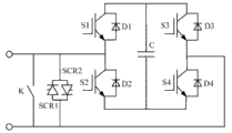
In the present embodiment, the full-bridge submodule as shown in Figure 4, the full-bridge submodule comprises four all-controlling power electronics device S1, S2, S3, S4, four diode D1, D2, D3, D4, a capacitor C, two thyristor SCR1, SCR2, a high-speed switch K, all-controlling power electronics device S1 and diode D1, S2 and D2, S3 and D3, S4 and D4 be reverse parallel connection respectively, be that the all-controlling power electronics device anode is connected with the diode negative terminal, the all-controlling power electronics device negative terminal is connected with the diode anode; Thyristor SCR1, SCR2 and reverse parallel connection, namely the SCR1 anode is connected with the SCR2 negative terminal, and the SCR1 negative terminal is connected with the SCR2 anode; All-controlling power electronics device S1 negative terminal and S2 anode connect and compose an end of described full-bridge submodule, and all-controlling power electronics device S3 negative terminal and S4 anode connect and compose the other end of described full-bridge submodule; All-controlling power electronics device S1 anode is connected with capacitor C one end with the S3 anode, and all-controlling power electronics device S4 negative terminal, S2 negative terminal and the capacitor C other end are connected; High-speed switch K is connected in described full-bridge submodule two ends; The anti-parallel thyristor that SCR1 and SCR2 form is to being connected in described full-bridge submodule two ends.
In the present embodiment, clamper Shuangzi module as shown in Figure 5, clamper Shuangzi module includes five all-controlling power electronics device S1, S2, S3, S4, S5, seven diode D1, D2, D3, D4, D5, D6, D7, two capacitor C 1, C2, two thyristor SCR1, SCR2, a high-speed switch K, wherein: all-controlling power electronics device S1 and diode D1, S2 and D2, S3 and D3, S4 and D4, S5 and D5 be reverse parallel connection respectively; Thyristor SCR1, SCR2 and reverse parallel connection; All-controlling power electronics device S1 negative terminal and S2 anode connect and compose an end of described clamper Shuangzi module, and S3 negative terminal and S4 anode connect and compose the other end of described clamper Shuangzi module; All-controlling power electronics device S1 anode is connected with S5 anode, capacitor C1 one end and diode D7 anode; All-controlling power electronics device S2 negative terminal is connected with diode D6 anode with the capacitor C1 other end; All-controlling power electronics device S3 anode is connected with diode D7 negative pole with capacitor C2 one end; All-controlling power electronics device S4 negative terminal links to each other with S5 negative terminal, the capacitor C2 other end and diode D6 negative pole; High-speed switch K is connected in described clamper Shuangzi module two ends; The anti-parallel thyristor that SCR1 and SCR2 form is to being connected in described clamper Shuangzi module two ends.Namely increased an all-controlling power electronics device-diode inverse parallel on the basis of full-bridge submodule to, two diodes and an electric capacity.
In the present embodiment, full-bridge submodule in parallel as shown in Figure 6, clamper Shuangzi module comprises and includes eight all-controlling power electronics device S11, S21, S31, S41, S12, S22, S32, S42, eight diode D11, D21, D31, D41, D12, D22, D32, D42, a capacitor C, two thyristor SCR1, SCR2, a high-speed switch K, wherein: all-controlling power electronics device S11 and diode D11, S21 and D21, S31 and D31, S41 and D41, S12 and D12, S22 and D22, S32 and D32, S42 and D42 be reverse parallel connection respectively; Thyristor SCR1, SCR2 and reverse parallel connection; All-controlling power electronics device S11 negative terminal and S12 negative terminal, S21 anode, S22 anode connect and compose an end of described full-bridge submodule in parallel, and all-controlling power electronics device S31 negative terminal and S32 negative terminal, S41 anode, S42 anode connect and compose the other end of described full-bridge submodule; All-controlling power electronics device S11 anode is connected with S12 anode, S31 anode, S32 anode and capacitor C one end, and all-controlling power electronics device S41 negative terminal is connected with S42 negative terminal, S21 negative terminal, S22 negative terminal and the capacitor C other end; High-speed switch K is connected in described full-bridge submodule two ends; The anti-parallel thyristor that SCR1 and SCR2 form is to being connected in described full-bridge submodule two ends.An all-controlling power electronics device-diode the inverse parallel that is about to full-bridge submodule correspondence position is right to changing two all-controlling power electronics devices-diode inverse parallel into.
In the present embodiment, clamper Shuangzi module in parallel as shown in Figure 7, clamper Shuangzi module in parallel includes ten all-controlling power electronics device S11, S21, S31, S41, S51, S12, S22, S32, S42, S52,12 diode D11, D21, D31, D41, D51, D12, D22, D32, D42, D52, D6, D7, two capacitor C 1, C2, two thyristor SCR1, SCR2, a high-speed switch K, wherein: all-controlling power electronics device S11 and diode D11, S21 and D21, S31 and D31, S41 and D41, S51 and D51, S12 and D12, S22 and D22, S32 and D32, S42 and D42, S52 and D52 be reverse parallel connection respectively; Thyristor SCR1, SCR2 and reverse parallel connection; All-controlling power electronics device S11 negative terminal and S12 negative terminal, S21 anode, S22 anode connect and compose an end of described clamper Shuangzi module in parallel, and S31 negative terminal and S32 negative terminal, S41 anode, S42 anode connect and compose the other end of described clamper Shuangzi module in parallel; All-controlling power electronics device S11 anode is connected with S12 anode, S51 anode, S52 anode, capacitor C1 one end and diode D7 anode; All-controlling power electronics device S21 negative terminal is connected with S22 negative terminal, the capacitor C1 other end and diode D6 anode; All-controlling power electronics device S31 anode is connected with S32 anode, capacitor C2 one end and diode D7 negative pole; All-controlling power electronics device S41 negative terminal links to each other with S42 negative terminal, S51 negative terminal, S52 negative terminal, the capacitor C2 other end and diode D6 negative pole; High-speed switch K is connected in described clamper Shuangzi module in parallel two ends; The anti-parallel thyristor that SCR1 and SCR2 form is to being connected in described clamper Shuangzi module in parallel two ends.A full-control type device-diode inverse parallel that is about to clamper Shuangzi module in parallel correspondence position is right to changing two full-control type device-diode inverse parallels into.
Operation principle of the present utility model is as follows:
Converting plant is converted into direct current with the three-phase alternating current of sending end electrical network and delivers to Inverter Station by built on stilts electric power transmission line, and Inverter Station is converted to three-phase alternating current with direct current and sends into the receiving end electrical network.
The Y0/Y of converting plant and Y0/ △ connect transformer the three-phase alternating current that the sending end electrical network provides are carried out the electric pressure conversion, and the three-phase alternating current of 30 ° of phase angle differences is provided for two six fluctuation bridges up and down of 12 pulsation thyristor converter device R.12 pulsation thyristor converter device R are converted to direct current with three-phase alternating current.The harmonic wave that alternating current filter ACF filtering 12 pulsation thyristor converter device R operations produce, and compensate the reactive power that 12 pulsation thyristor converter device R operations consume.Ripple in the direct current of smoothing reactor SRr is stabilized, and avoids discontinuous current, prevents that the impact that DC power transmission line produces from entering 12 pulsation thyristor converter devices, is convenient to the realization of transmission line fast transient protection.The harmonic wave that DC filter DCF produces in DC side in order to filtering converting plant 12 pulsation thyristor converter devices.Power overhead network OHL delivers to Inverter Station with direct current.
The modularization multi-level converter VSC of Inverter Station sends power overhead network OHL here direct current and is converted to alternating current.The three-phase alternating current that the Y0/ △ connection transformer of Inverter Station converts to modularization multi-level converter VSC carries out the electric pressure conversion and flows to the receiving end electrical network.Smoothing reactor SRi avoids discontinuous current, prevents that the impact that DC power transmission line produces from entering modularization multi-level converter, also is convenient to the realization of transmission line fast transient protection.Inverter Station does not need to dispose alternating current filter and DC filter owing to adopted modularization multi-level converter.In the present embodiment, converting plant adopts and decide Current Control and minimum trigger angle restriction, and stand firm direct voltage and decide Reactive Power Control of inversion is perhaps decided active power, decided Reactive Power Control and direct voltage limits.The submodule Switching Strategy of Inverter Station modularization multi-level converter adopts nearest level to approach modulation and submodule electric capacity balance policy, and modularization multi-level converter three alternate employing circulation suppress strategy.
The modularization multi-level converter VSC of Inverter Station is by a plurality of full-bridge submodules, or clamper Shuangzi module, or full-bridge submodule in parallel, or the series connection of clamper two-in-parallel submodule constitutes, can locking dc-side short-circuit electric current, after detecting DC side and being short-circuited, the full control power electronic device that locking is all, the dc-side short-circuit electric current can be eliminated immediately.If DC side is transient fault, after the dc-side short-circuit electric current is eliminated, through of short duration go the free time after, DC transmission system namely can be recovered normally to send.Namely similar with the conventional high-tension direct current transportation, need not dc circuit breaker and just can effectively handle the DC side fault, realize restarting of DC transmission system fast.
Claims (10)
1. compound HVDC (High Voltage Direct Current) transmission system, it is characterized in that including at least one converting plant, an Inverter Station and built on stilts electric power transmission line, converting plant and Inverter Station all comprise positive pole and negative pole, wherein converting plant adopts the thyristor converter device, and the positive pole of thyristor converter device and negative pole all comprise one 12 pulsation thyristor converter device at least; Inverter Station adopts the voltage source converter with direct current troubleshooting capability, and the positive pole of voltage source converter and negative pole all comprise the modularization multi-level converter of two series connection at least; Each both positive and negative polarity tie point of standing is in bipolar, the big earthed return of one pole according to DC transmission system or one pole metallic return operational mode is connected with earth mat in earth electrode or the station, links to each other by making somebody a mere figurehead electric power transmission line between converting plant and the Inverter Station.
2. compound HVDC (High Voltage Direct Current) transmission system according to claim 1, it is characterized in that above-mentioned converting plant and Inverter Station all dispose smoothing reactor, converting plant every extremely all configuring direct current filter and alternating current filter, every DC filter and the alternating current filter of extremely all not disposing of Inverter Station.
3. compound HVDC (High Voltage Direct Current) transmission system according to claim 1, the positive pole and the 12 set pulsation thyristor converter devices of negative pole that it is characterized in that above-mentioned thyristor converter device include six fluctuation bridges and following six fluctuation bridges, last six fluctuation bridges connect transformer Y side with a Y0/Y and are connected, six fluctuation bridges are connected with a Y0/ △ connection transformer △ side down, or last six fluctuation bridges of 12 pulsation thyristor converter devices reach down, and six fluctuation bridges are connected respectively with the △ side with the Y side that a Y0/Y/ △ connects transformer.
4. according to each described compound HVDC (High Voltage Direct Current) transmission system of claim 1 to 3, it is characterized in that the set voltage source converter of above-mentioned Inverter Station is three-phase six brachium pontis structures, each brachium pontis is made up of a reactor and several change of current modules, and several change of current module series connection back one sides connect the corresponding phase port of transformer △ side by reactor with Y0/ △ and connect.
5. compound HVDC (High Voltage Direct Current) transmission system according to claim 4 is characterized in that adopting complete dipolar configuration, and namely anodal, negative pole all can adopt one pole the earth or one pole metallic return operational mode independent operating.
6. compound HVDC (High Voltage Direct Current) transmission system according to claim 5, it is characterized in that the change of current module in the set voltage source converter of above-mentioned Inverter Station adopts the full-bridge submodule, or clamper Shuangzi module, or full-bridge submodule in parallel, or clamper two-in-parallel submodule.
7. compound HVDC (High Voltage Direct Current) transmission system according to claim 6, it is characterized in that above-mentioned full-bridge submodule comprises four all-controlling power electronics device S1, S2, S3, S4, four diode D1, D2, D3, D4, a capacitor C, two thyristor SCR1, SCR2, a high-speed switch K, all-controlling power electronics device S1 and diode D1, S2 and D2, S3 and D3, S4 and D4 be reverse parallel connection respectively, be that the all-controlling power electronics device anode is connected with the diode negative terminal, the all-controlling power electronics device negative terminal is connected with the diode anode; Thyristor SCR1, SCR2 and reverse parallel connection, namely the SCR1 anode is connected with the SCR2 negative terminal, and the SCR1 negative terminal is connected with the SCR2 anode; All-controlling power electronics device S1 negative terminal and S2 anode connect and compose an end of described full-bridge submodule, and all-controlling power electronics device S3 negative terminal and S4 anode connect and compose the other end of described full-bridge submodule; All-controlling power electronics device S1 anode is connected with capacitor C one end with the S3 anode, and all-controlling power electronics device S4 negative terminal, S2 negative terminal and the capacitor C other end are connected; High-speed switch K is connected in described full-bridge submodule two ends; The anti-parallel thyristor that SCR1 and SCR2 form is to being connected in described full-bridge submodule two ends.
8. compound HVDC (High Voltage Direct Current) transmission system according to claim 6, it is characterized in that above-mentioned clamper Shuangzi module includes five all-controlling power electronics device S1, S2, S3, S4, S5, seven diode D1, D2, D3, D4, D5, D6, D7, two capacitor C 1, C2, two thyristor SCR1, SCR2, a high-speed switch K, wherein: all-controlling power electronics device S1 and diode D1, S2 and D2, S3 and D3, S4 and D4, S5 and D5 be reverse parallel connection respectively; Thyristor SCR1, SCR2 and reverse parallel connection; All-controlling power electronics device S1 negative terminal and S2 anode connect and compose an end of described clamper Shuangzi module, and S3 negative terminal and S4 anode connect and compose the other end of described clamper Shuangzi module; All-controlling power electronics device S1 anode is connected with S5 anode, capacitor C1 one end and diode D7 anode; All-controlling power electronics device S2 negative terminal is connected with diode D6 anode with the capacitor C1 other end; All-controlling power electronics device S3 anode is connected with diode D7 negative pole with capacitor C2 one end; All-controlling power electronics device S4 negative terminal links to each other with S5 negative terminal, the capacitor C2 other end and diode D6 negative pole; High-speed switch K is connected in described clamper Shuangzi module two ends; The anti-parallel thyristor that SCR1 and SCR2 form is to being connected in described clamper Shuangzi module two ends, namely increased an all-controlling power electronics device-diode inverse parallel on the basis of full-bridge submodule to, two diodes and an electric capacity.
9. compound HVDC (High Voltage Direct Current) transmission system according to claim 6, it is characterized in that above-mentioned full-bridge submodule in parallel includes eight all-controlling power electronics device S11, S21, S31, S41, S12, S22, S32, S42, eight diode D11, D21, D31, D41, D12, D22, D32, D42, a capacitor C, two thyristor SCR1, SCR2, a high-speed switch K, wherein: all-controlling power electronics device S11 and diode D11, S21 and D21, S31 and D31, S41 and D41, S12 and D12, S22 and D22, S32 and D32, S42 and D42 be reverse parallel connection respectively; Thyristor SCR1, SCR2 and reverse parallel connection; All-controlling power electronics device S11 negative terminal and S12 negative terminal, S21 anode, S22 anode connect and compose an end of described full-bridge submodule in parallel, and all-controlling power electronics device S31 negative terminal and S32 negative terminal, S41 anode, S42 anode connect and compose the other end of described full-bridge submodule; All-controlling power electronics device S11 anode is connected with S12 anode, S31 anode, S32 anode and capacitor C one end, and all-controlling power electronics device S41 negative terminal is connected with S42 negative terminal, S21 negative terminal, S22 negative terminal and the capacitor C other end; High-speed switch K is connected in described full-bridge submodule two ends; The anti-parallel thyristor that SCR1 and SCR2 form is to being connected in described full-bridge submodule two ends, and an all-controlling power electronics device-diode inverse parallel that is about to full-bridge submodule correspondence position is right to changing two all-controlling power electronics devices-diode inverse parallel into.
10. compound HVDC (High Voltage Direct Current) transmission system according to claim 6, it is characterized in that above-mentioned clamper Shuangzi module in parallel includes ten all-controlling power electronics device S11, S21, S31, S41, S51, S12, S22, S32, S42, S52,12 diode D11, D21, D31, D41, D51, D12, D22, D32, D42, D52, D6, D7, two capacitor C 1, C2, two thyristor SCR1, SCR2, a high-speed switch K, wherein: all-controlling power electronics device S11 and diode D11, S21 and D21, S31 and D31, S41 and D41, S51 and D51, S12 and D12, S22 and D22, S32 and D32, S42 and D42, S52 and D52 be reverse parallel connection respectively; Thyristor SCR1, SCR2 and reverse parallel connection; All-controlling power electronics device S11 negative terminal and S12 negative terminal, S21 anode, S22 anode connect and compose an end of described clamper Shuangzi module in parallel, and S31 negative terminal and S32 negative terminal, S41 anode, S42 anode connect and compose the other end of described clamper Shuangzi module in parallel; All-controlling power electronics device S11 anode is connected with S12 anode, S51 anode, S52 anode, capacitor C1 one end and diode D7 anode; All-controlling power electronics device S21 negative terminal is connected with S22 negative terminal, the capacitor C1 other end and diode D6 anode; All-controlling power electronics device S31 anode is connected with S32 anode, capacitor C2 one end and diode D7 negative pole; All-controlling power electronics device S41 negative terminal links to each other with S42 negative terminal, S51 negative terminal, S52 negative terminal, the capacitor C2 other end and diode D6 negative pole; High-speed switch K is connected in described clamper Shuangzi module in parallel two ends; The anti-parallel thyristor that SCR1 and SCR2 form is to being connected in described clamper Shuangzi module in parallel two ends, and a full-control type device-diode inverse parallel that is about to clamper Shuangzi module in parallel correspondence position is right to changing two full-control type device-diode inverse parallels into.
Priority Applications (1)
| Application Number | Priority Date | Filing Date | Title |
|---|---|---|---|
| CN 201320030429 CN203166540U (en) | 2013-01-22 | 2013-01-22 | Combined type high-voltage direct current transmission system |
Applications Claiming Priority (1)
| Application Number | Priority Date | Filing Date | Title |
|---|---|---|---|
| CN 201320030429 CN203166540U (en) | 2013-01-22 | 2013-01-22 | Combined type high-voltage direct current transmission system |
Publications (1)
| Publication Number | Publication Date |
|---|---|
| CN203166540U true CN203166540U (en) | 2013-08-28 |
Family
ID=49027700
Family Applications (1)
| Application Number | Title | Priority Date | Filing Date |
|---|---|---|---|
| CN 201320030429 Expired - Lifetime CN203166540U (en) | 2013-01-22 | 2013-01-22 | Combined type high-voltage direct current transmission system |
Country Status (1)
| Country | Link |
|---|---|
| CN (1) | CN203166540U (en) |
Cited By (7)
| Publication number | Priority date | Publication date | Assignee | Title |
|---|---|---|---|---|
| CN103107549A (en) * | 2013-01-22 | 2013-05-15 | 南方电网科学研究院有限责任公司 | Compound type high-voltage direct current transmission system |
| CN103647298A (en) * | 2013-11-27 | 2014-03-19 | 中国南方电网有限责任公司电网技术研究中心 | Full-current composite high-voltage direct current transmission system |
| CN105119252A (en) * | 2015-08-20 | 2015-12-02 | 南方电网科学研究院有限责任公司 | Ground loop and metal loop fast conversion method and device thereof in double twelve-pulse direct current transmission system |
| CN105634026A (en) * | 2015-10-16 | 2016-06-01 | 华北电力大学 | Line commutated converter structure for anti-parallel thyristor-based full bridge submodule converter |
| CN108736506A (en) * | 2018-08-02 | 2018-11-02 | 南方电网科学研究院有限责任公司 | A kind of HVDC transmission system |
| CN108808717A (en) * | 2018-06-26 | 2018-11-13 | 南方电网科学研究院有限责任公司 | High voltage direct current phase-triggered control method based on single-phase locking phase |
| WO2019068437A1 (en) * | 2017-10-02 | 2019-04-11 | Siemens Aktiengesellschaft | Direct-current transmission system |
-
2013
- 2013-01-22 CN CN 201320030429 patent/CN203166540U/en not_active Expired - Lifetime
Cited By (11)
| Publication number | Priority date | Publication date | Assignee | Title |
|---|---|---|---|---|
| CN103107549A (en) * | 2013-01-22 | 2013-05-15 | 南方电网科学研究院有限责任公司 | Compound type high-voltage direct current transmission system |
| CN103647298A (en) * | 2013-11-27 | 2014-03-19 | 中国南方电网有限责任公司电网技术研究中心 | Full-current composite high-voltage direct current transmission system |
| CN105119252A (en) * | 2015-08-20 | 2015-12-02 | 南方电网科学研究院有限责任公司 | Ground loop and metal loop fast conversion method and device thereof in double twelve-pulse direct current transmission system |
| CN105119252B (en) * | 2015-08-20 | 2018-09-18 | 南方电网科学研究院有限责任公司 | The method and its device of Ground return and metallic return rapid translating in a kind of pair of 12 pulsating direct current transmission systems |
| CN105634026A (en) * | 2015-10-16 | 2016-06-01 | 华北电力大学 | Line commutated converter structure for anti-parallel thyristor-based full bridge submodule converter |
| CN105634026B (en) * | 2015-10-16 | 2019-02-26 | 华北电力大学 | A kind of line commutation converter structure based on anti-parallel thyristor full-bridge submodule inverter |
| WO2019068437A1 (en) * | 2017-10-02 | 2019-04-11 | Siemens Aktiengesellschaft | Direct-current transmission system |
| CN108808717A (en) * | 2018-06-26 | 2018-11-13 | 南方电网科学研究院有限责任公司 | High voltage direct current phase-triggered control method based on single-phase locking phase |
| CN108808717B (en) * | 2018-06-26 | 2021-08-13 | 南方电网科学研究院有限责任公司 | High-voltage direct-current trigger phase control method based on single-phase lock |
| CN108736506A (en) * | 2018-08-02 | 2018-11-02 | 南方电网科学研究院有限责任公司 | A kind of HVDC transmission system |
| CN108736506B (en) * | 2018-08-02 | 2023-12-01 | 南方电网科学研究院有限责任公司 | High-voltage direct-current transmission system |
Similar Documents
| Publication | Publication Date | Title |
|---|---|---|
| CN103107549A (en) | Compound type high-voltage direct current transmission system | |
| CN203166540U (en) | Combined type high-voltage direct current transmission system | |
| US10084387B2 (en) | LCC and MMC series-connected HVDC system with DC fault ride-through capability | |
| US9502991B2 (en) | Hybrid converter and wind power generating system | |
| CN102969732B (en) | Mixed bipolar direct current (DC) transmission system | |
| Miura et al. | Modular multilevel matrix converter for low frequency AC transmission | |
| WO2015176549A1 (en) | Tripolar flexible direct-current power transmission system and method | |
| CN103001242A (en) | HVDC (high voltage direct current controller) and UPFC (unified power flow controller) system based on modularized multi-level converter | |
| CN104852583A (en) | High-frequency link multi-level direct-current transformer used for middle- low-voltage direct current distribution | |
| CN108173442B (en) | Isolated modular multilevel converter based on high-frequency chain technology | |
| CN103427658A (en) | High-voltage DC-DC conversion device based on multi-winding transformer | |
| Zhang et al. | A three-phase five-level inverter with high DC voltage utilization and self-balancing capacity of floating capacitor | |
| CN103441676A (en) | Modularized device for conversion between high-voltage direct current and direct current | |
| Zhou et al. | The development of HVDC transmission system | |
| CN113726136B (en) | conversion device | |
| CN102496932A (en) | Parallel voltage sag compensation device | |
| CN110224622B (en) | Sub-module capacitor voltage fluctuation suppression method for full-bridge modular multilevel converter | |
| Liu et al. | An overview of self-commutating converters and their application in transmission and distribution | |
| CN204578373U (en) | A kind of High Frequency Link many level DCs transformer for mesolow DC distribution | |
| CN103647298A (en) | Full-current composite high-voltage direct current transmission system | |
| CN102983586A (en) | High voltage direct current transmission (HVDC) and unified power flow controller (UPFC) system based on three-level inverter voltage source current converter | |
| CN113452276B (en) | CCC-PHC type hybrid cascade direct current converter, rectifying station, inverter station and power transmission system | |
| CN214959327U (en) | Energy storage circuit and modular multilevel converter | |
| CN210821908U (en) | High-speed railway load characteristic adjusting device based on modularization multi-level | |
| CN203553960U (en) | Full-current composite high-voltage direct-current transmission system |
Legal Events
| Date | Code | Title | Description |
|---|---|---|---|
| C14 | Grant of patent or utility model | ||
| GR01 | Patent grant | ||
| CX01 | Expiry of patent term | ||
| CX01 | Expiry of patent term |
Granted publication date: 20130828 |