CN203166360U - Switch cabinet valve opening trolley - Google Patents
Switch cabinet valve opening trolley Download PDFInfo
- Publication number
- CN203166360U CN203166360U CN 201320140925 CN201320140925U CN203166360U CN 203166360 U CN203166360 U CN 203166360U CN 201320140925 CN201320140925 CN 201320140925 CN 201320140925 U CN201320140925 U CN 201320140925U CN 203166360 U CN203166360 U CN 203166360U
- Authority
- CN
- China
- Prior art keywords
- joint
- connecting rod
- brake line
- trolley
- valve
- Prior art date
- Legal status (The legal status is an assumption and is not a legal conclusion. Google has not performed a legal analysis and makes no representation as to the accuracy of the status listed.)
- Expired - Lifetime
Links
Images


Landscapes
- Mechanically-Actuated Valves (AREA)
Abstract
本实用新型涉及一种开关柜活门开启小车,包括连杆机构、接头机构、接头调整机构、助力机构;连杆机构包括横连杆、纵连杆;接头机构包括设置于横连杆两端的接头组件,接头组件包括侧杆、一对驱动接头;接头调整机构包括刹车线、设置于纵连杆上的第一刹车线固定部分、控制装置、设置于一个驱动接头上的第二刹车线固定部分及另一个驱动接头上的刹车线活动部分,刹车线依次连接于一组接头组件的第二刹车线固定部分和刹车线活动部分、第一刹车线固定部分、另一组接头组件上的刹车线活动部分和第二刹车线固定部分;助力机构包括操作杆。本实用新型能辅助人员开启活门,保证工作人员和设备的安全,并能排除活门的机械卡涩故障。其结构简单、实用性强。
The utility model relates to a trolley for opening the valve of a switch cabinet, which comprises a connecting rod mechanism, a joint mechanism, a joint adjusting mechanism and a booster mechanism; the connecting rod mechanism includes a horizontal connecting rod and a vertical connecting rod; Assembly, the joint assembly includes a side bar, a pair of drive joints; the joint adjustment mechanism includes a brake line, a first brake line fixing part arranged on a longitudinal link, a control device, and a second brake line fixing part set on a drive joint And the movable part of the brake line on the other drive connector, the brake line is connected to the second fixed part of the brake line and the movable part of the brake line, the fixed part of the first brake line, and the brake line on the other set of joint components in sequence The movable part and the fixed part of the second brake line; the booster mechanism includes an operating rod. The utility model can assist personnel to open the valve, guarantee the safety of staff and equipment, and can eliminate the mechanical jamming failure of the valve. The utility model has the advantages of simple structure and strong practicability.
Description
技术领域 technical field
本实用新型涉及一种用于辅助开启开关柜的活门的开启小车。 The utility model relates to an opening trolley for assisting in opening a valve of a switch cabinet.
背景技术 Background technique
国家电网公司《输变电设备状态检修规程》要求对于新投变电站以及大修技改之后的变电设备需进行带电核对相序工作。在核对相序的过程中,由于目前设备的结构以及缺少相应的专用工具,使得操作人员必须进入开关柜内并手动推动活门的驱动装置而使活门开启,此时工作人员与带电触头的距离仅仅略大于0.7米,刚好达到10kV设备的规定安全距离,但这样对工作人员的人身安全仍构成极大地威胁,同时也给设备带来安全隐患。 The State Grid Corporation of China's "Condition Maintenance Regulations for Power Transmission and Transformation Equipment" requires that new substations and substation equipment after overhaul and technical transformation need to be checked for phase sequence work. In the process of checking the phase sequence, due to the structure of the current equipment and the lack of corresponding special tools, the operator must enter the switch cabinet and manually push the drive device of the valve to open the valve. At this time, the distance between the staff and the live contact It is only slightly larger than 0.7 meters, just reaching the specified safety distance of 10kV equipment, but this still poses a great threat to the personal safety of the staff, and also brings potential safety hazards to the equipment.
通过对技术通报的查阅发现,开关柜活门的机械卡涩故障已经成为目前开关柜主流故障之一。而目前的活门装置在试验位置时处于关闭状态下,必须依靠操作人员进入开关柜内并手动调整活门驱动装置,排除卡涩故障使活门开启。此种方式比较危险,操作失误时易造成操作人员的触电事故,安全性不高。并且传统的活门机械故障处理均需要母线停运,这给电网运行带来巨大损失,特别是对于重要线路负荷,不可能停电检修,这对电网运行有着相当大的隐患。 Through the review of the technical bulletin, it is found that the mechanical jamming fault of the switchgear valve has become one of the mainstream faults of the switchgear. However, the current valve device is in the closed state when it is in the test position, and it is necessary to rely on the operator to enter the switch cabinet and manually adjust the valve driving device to remove the jamming fault to open the valve. This kind of mode is more dangerous, and it is easy to cause the electric shock accident of the operator when the operation is wrong, and the safety is not high. Moreover, the traditional valve mechanical failure treatment requires the bus to be out of service, which brings huge losses to the operation of the power grid, especially for important line loads, it is impossible to cut off the power for maintenance, which has considerable hidden dangers to the operation of the power grid.
发明内容 Contents of the invention
本实用新型的目的是提供一种能够带电开启开关柜活门并能在不停母线的条件下对活门卡涩故障进行处理的小车。 The purpose of the utility model is to provide a trolley that can open the valve of the switch cabinet with electricity and can handle the stuck fault of the valve under the condition of not stopping the bus.
为达到上述目的,本实用新型采用的技术方案是: For achieving the above object, the technical scheme that the utility model adopts is:
一种开关柜活门开启小车,用于开启变电站中的开关柜的活门,所述的开关柜上设置有驱动所述的活门开启的活门驱动装置,所述的开关柜活门开启小车包括连杆机构、接头机构、接头调整机构、助力机构; A switchgear valve opening trolley is used to open the valve of a switchgear in a substation. The switchgear is provided with a valve driving device that drives the valve to be opened. The switchgear valve opening trolley includes a linkage mechanism, Joint mechanism, joint adjustment mechanism, booster mechanism;
所述的连杆机构包括能够调节长度并沿X方向延伸的横连杆、垂直连接于所述的横连杆的中部并沿Y方向延伸的纵连杆; The link mechanism includes a horizontal link that can be adjusted in length and extends along the X direction, and a vertical link that is vertically connected to the middle of the horizontal link and extends along the Y direction;
所述的接头机构包括相对称的设置于所述的横连杆两端的两组接头组件,所述的接头组件包括与所述的横连杆相连接并沿Z方向延伸的侧杆、设置于所述的侧杆上的与所述的活门驱动装置相配合并能够沿Z方向移动的一对驱动接头,所述的驱动接头通过接头连接装置设置于所述的侧杆上; The joint mechanism includes two sets of joint assemblies symmetrically arranged at both ends of the horizontal connecting rod, and the joint assembly includes a side bar connected with the horizontal connecting rod and extending along the Z direction, arranged on A pair of drive joints on the side bar that are matched with the valve drive device and can move in the Z direction, and the drive joints are arranged on the side bar through a joint connection device;
所述的接头调整机构包括刹车线、设置于所述的纵连杆上并能够沿Y方向移动的第一刹车线固定部分、驱动所述的第一刹车线固定部分沿Y方向移动的控制装置、设置于每组所述的接头组件中的一个所述的驱动接头上的第二刹车线固定部分及另一个所述的驱动接头上的刹车线活动部分,所述的刹车线依次连接于位于一组所述的接头组件上的第二刹车线固定部分和刹车线活动部分、所述的第一刹车线固定部分、位于另一组所述的接头组件上的刹车线活动部分和第二刹车线固定部分,且所述的刹车线与所述的第一刹车线固定部分和所述的第二刹车线固定部分相固定连接、与所述的刹车线活动部分相活动连接;
The joint adjustment mechanism includes a brake wire, a first brake wire fixing part arranged on the longitudinal link and capable of moving in the Y direction, and a control device that drives the first brake wire fixing part to move in the
所述的助力机构包括与所述的连杆机构相连接并沿Y方向延伸的操作杆,所述的操作杆与所述的纵连杆位于所述的横连杆的同侧。 The booster mechanism includes an operating rod connected with the linkage mechanism and extending along the Y direction, the operating rod and the longitudinal connecting rod are located on the same side of the horizontal connecting rod.
优选的,所述的横连杆包括第一横杆、设置于所述的第一横杆的两端并与其同向的两根第二横杆,所述的第一横杆上开设有沿X方向延伸的第一长孔,所述的第二横杆通过与所述的第一长孔相配合的第一螺丝连接于所述的第一横杆的两端,所述的接头机构设置于所述的第二横杆上。 Preferably, the horizontal connecting rod includes a first horizontal rod, two second horizontal rods arranged at both ends of the first horizontal rod and in the same direction as the first horizontal rod. The first long hole extending in the X direction, the second crossbar is connected to both ends of the first crossbar through the first screw matched with the first long hole, and the joint mechanism is set on the second crossbar.
优选的,所述的第一横杆的截面为不封闭的矩形框架并形成矩形的内腔空间,所述的第二横杆插入所述的内腔空间中。 Preferably, the section of the first cross bar is an unclosed rectangular frame and forms a rectangular inner cavity space, and the second cross bar is inserted into the inner cavity space.
优选的,所述的开关柜内设置有轨道,所述的侧杆的下部设置有与所述的轨道相配合的若干个滚轮。 Preferably, the switch cabinet is provided with a track, and the lower part of the side bar is provided with several rollers matched with the track.
优选的,每个所述的侧杆的下部设置有两个所述的滚轮,所述的侧杆的下部固定设置有沿Y方向延伸的安装架,所述的滚轮沿Y方向排布安装于所述的安装架上。 Preferably, the lower part of each side bar is provided with two said rollers, the lower part of said side bar is fixedly provided with a mounting bracket extending along the Y direction, and said rollers are arranged and installed on on the mounting bracket.
优选的,所述的接头连接装置包括开设于所述的侧杆上并沿Z方向延伸的第二长孔、与所述的第二长孔相配合的第二螺丝,所述的驱动接头与所述的第二螺丝相固定连接并位于所述的侧杆的外侧,所述的第二刹车线固定部分或所述的刹车线活动部分与所述的第二螺丝相固定连接并位于所述的侧杆的内侧,所述的驱动接头与所述的侧杆之间还设置有沿所述的Z方向伸缩的弹簧。 Preferably, the joint connection device includes a second long hole opened on the side bar and extending along the Z direction, a second screw matched with the second long hole, and the drive joint is connected to the second long hole. The second screw is fixedly connected and located on the outside of the side bar, and the second brake line fixed part or the brake line movable part is fixedly connected with the second screw and located on the A spring stretching along the Z direction is also arranged between the drive joint and the side rod on the inner side of the side rod.
优选的,所述的纵连杆上开设有沿Y方向的第三长孔,所述的控制装置包括沿Y方向设置于所述的纵连杆内的蜗杆、与所述的蜗杆相配合的螺母、驱动所述的蜗杆转动的动力装置,所述的第一刹车线固定部分穿过所述的第三长孔与所述的螺母相固定连接。 Preferably, the longitudinal connecting rod is provided with a third long hole along the Y direction, and the control device includes a worm arranged in the longitudinal connecting rod along the Y direction, and a A nut, a power device that drives the worm to rotate, and the first brake line fixing part passes through the third long hole and is fixedly connected with the nut.
优选的,所述的动力装置包括设置于所述的纵连杆的端部并与所述的蜗杆相连接的曲手柄。 Preferably, the power device includes a crank handle arranged at the end of the longitudinal connecting rod and connected with the worm.
优选的,所述的连杆机构上设置有两根所述的操作杆,所述的操作杆相对称的设置于所述的纵连杆的X方向的两侧,所述的操作杆的一端固定连接于所述的横连杆上,所述的操作杆的另一端设置有操作把手。 Preferably, the linkage mechanism is provided with two operating rods, the operating rods are symmetrically arranged on both sides of the longitudinal connecting rod in the X direction, and one end of the operating rod It is fixedly connected to the horizontal connecting rod, and the other end of the operating rod is provided with an operating handle.
优选的,所述的操作杆通过标准螺丝与所述的连杆机构相连接。 Preferably, the operating rod is connected with the linkage mechanism through standard screws.
由于上述技术方案运用,本实用新型与现有技术相比具有下列优点:本实用新型的开关柜活门开启小车能够辅助工作人员开启开关柜的活门,增加工作人员与带电触头的距离从而保证工作人员和设备的安全,并能够在不停母线的情况下排除活门的机械卡涩故障,保证电网运行。其结构简单、操作便捷、实用性强,具有较高的推广价值。 Due to the application of the above technical solutions, the utility model has the following advantages compared with the prior art: the switchgear valve opening trolley of the utility model can assist the staff to open the valve of the switchgear, increase the distance between the staff and the live contact to ensure the work The safety of personnel and equipment can be eliminated, and the mechanical jamming fault of the valve can be eliminated without stopping the bus, so as to ensure the operation of the power grid. The utility model has the advantages of simple structure, convenient operation, strong practicability and high popularization value.
附图说明 Description of drawings
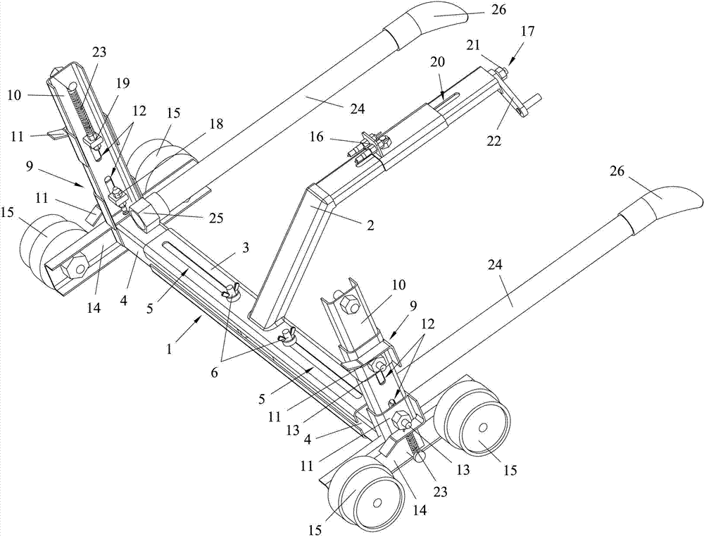
附图1为本实用新型的开关柜活门开启小车的立体图。
Accompanying
附图2为本实用新型的开关柜活门开启小车的立体图。
Accompanying
附图3为本实用新型的开关柜活门开启小车的立体图。
Accompanying
附图4为本实用新型的开关柜活门开启小车的主视图。
Accompanying
附图5为本实用新型的开关柜活门开启小车的后视图。
Accompanying
附图6为本实用新型的开关柜活门开启小车的俯视图。
Accompanying
附图7为本实用新型的开关柜活门开启小车的左视图。
Accompanying
以上附图中:1、横连杆;2、纵连杆;3、第一横杆;4、第二横杆;5、第一长孔;6、第一螺丝;7、元宝螺丝;8、双头螺杆;9、接头组件;10、侧杆;11、驱动接头;12、第二长孔;13、第二螺丝;14、安装架;15、滚轮;16、第一刹车线固定部分;17、控制装置;18、第二刹车线固定部分;19、刹车线活动部分;20、第三长孔;21、蜗杆;22、曲手柄;23、弹簧;24、操作杆;25、标准螺丝;26、操作把手。 In the above accompanying drawings: 1, horizontal connecting rod; 2, vertical connecting rod; 3, the first cross bar; 4, the second cross bar; 5, the first long hole; 6, the first screw; 7, ingot screw; 8 , double-headed screw; 9, joint assembly; 10, side rod; 11, drive joint; 12, second long hole; 13, second screw; 14, mounting frame; 15, roller; 16, first brake line fixing part ; 17, control device; 18, the second brake line fixed part; 19, brake line movable part; 20, the third long hole; 21, worm; 22, crank handle; 23, spring; 24, operating lever; 25, standard Screw; 26, operating handle.
具体实施方式 Detailed ways
下面结合附图所示的实施例对本实用新型作进一步描述。 The utility model will be further described below in conjunction with the embodiment shown in the accompanying drawings.
实施例一:参见附图1至附图7所示。变电站中的开关柜具有可开启的活门,开关柜内设置有用来驱动活门开启的活门驱动装置并设置有轨道。
Embodiment 1: See accompanying
一种用于辅助工作人员通过活门驱动装置来开启活门的开关柜活门开启小车,其包括连杆机构、接头机构、接头调整机构、助力机构。 A switch cabinet valve opening trolley for assisting workers to open the valve through a valve driving device, which includes a link mechanism, a joint mechanism, a joint adjustment mechanism, and a booster mechanism.
连杆机构包括能够调节长度并沿X方向延伸的横连杆1、垂直连接于横连杆1的中部并沿Y方向延伸的纵连杆2。其中,横连杆1包括第一横杆3、设置于第一横杆3的两端并与其同向的两根第二横杆4。第一横杆3的截面为不封闭的矩形框架并形成矩形的内腔空间,第二横杆4插入内腔空间中并能够在其中沿X方向滑动。第一横杆3上开设有沿X方向延伸的两个第一长孔5,分别与两根第二横杆4相对应,第二横杆4通过与第一长孔5相配合的第一螺丝6连接于第一横杆3的两端。第一螺丝6可采用元宝螺丝7和双头螺杆8来配合固定第一横杆3和第二横杆4。当需要调节横连杆1的长度时,旋松第一螺丝6再使第一横杆3和第二横杆4相对滑动至合适位置,最后旋紧第一螺丝6即可。纵连杆2采用具有一弯折处的杆件,其一端焊接固定在横连杆1的中央,即焊接固定在第一横杆3的中央。
The link mechanism includes a
接头机构设置于第二横杆4上。接头机构包括相对称的设置于横连杆1两端的两组接头组件9。接头组件9包括与横连杆1相连接并沿Z方向延伸的侧杆10、设置于侧杆10上的与活门驱动装置相配合并能够沿Z方向移动的一对驱动接头11。驱动接头11通过接头连接装置设置于侧杆10上。接头连接装置包括开设于侧杆10上并沿Z方向延伸的第二长孔12、与第二长孔12相配合的第二螺丝13;驱动接头11与第二螺丝13相固定连接并位于侧杆10的外侧(该“外侧”指侧杆10上背离横连杆1的一侧)。侧杆10的截面也为不封闭的矩形框架,侧杆10的Y方向的两端向其内侧(该“内侧”指侧杆10上靠近横连杆1的一侧)弯折。侧杆10的下部固定设置有沿Y方向延伸的安装架14,每个安装架14上设置有两个滚轮15,滚轮15沿Y方向排布安装于安装架14上,该滚轮15与开关柜内的轨道相配合。
The joint mechanism is arranged on the
接头调整机构包括刹车线(刹车线在附图中未示出)、设置于纵连杆2上并能够沿Y方向移动的第一刹车线固定部分16、驱动第一刹车线固定部分16沿Y方向移动的控制装置17、设置于每组接头组件9中的一个驱动接头11上的第二刹车线固定部分18及另一个驱动接头11上的刹车线活动部分19。其中,在每个接头组件9上,第二刹车线固定部分18设置于位于下方的那个驱动接头11上,而刹车线活动部分19设置于位于上方的那个驱动接头11上。
The joint adjustment mechanism includes a brake wire (the brake wire is not shown in the drawings), a first brake
纵连杆2的上方开设有沿Y方向的第三长孔20并且纵连杆2的至少一部分为空心结构。控制装置17包括沿Y方向设置于纵连杆2内的蜗杆21、与蜗杆21相配合的螺母、驱动蜗杆21转动的动力装置,第一刹车线固定部分16穿过第三长孔20与螺母相固定连接。动力装置包括设置于纵连杆2的端部并与蜗杆21相连接的曲手柄22。当手摇曲手柄22时,其带动蜗杆21转动,从而促使螺母带动第一刹车线固定部分16沿蜗杆21的轴向,即Y方向移动。
A third
第二刹车线固定部分18与每组接头组件9中位于下方的那个驱动接头11所连接的第二螺丝13相连接,且其位于侧杆10的内侧;而刹车线活动部分19则与每组接头组件9中位于上方的那个驱动接头11所连接的第二螺丝13相连接,且其也位于侧杆10的内侧。也就是说,第二刹车线固定部分18和刹车线活动部分19均设置于侧杆10的弯折的端部所形成的内凹空间中。驱动接头11与侧杆10之间还设置有沿Z方向伸缩的弹簧23。其中,与上方的驱动接头11相连接的弹簧23位于侧杆10的内侧,其一端固定连接在侧杆10的上端,而另一端通过与刹车线活动部分19的连接而与驱动接头11相连接。而与下方的驱动接头11相连接的弹簧23则位于侧杆10的外侧,其一端通过固定连接在侧杆10下部的安装架14上而与侧杆10相连接,另一端直接与驱动接头11相连接。
The second brake
刹车线依次连接于位于一组接头组件9上的第二刹车线固定部分18和刹车线活动部分19、第一刹车线固定部分16、位于另一组接头组件9上的刹车线活动部分19和第二刹车线固定部分18,且刹车线与第一刹车线固定部分16和第二刹车线固定部分18相固定连接、与刹车线活动部分19相活动连接。当第一刹车线固定部分16沿Y方向移动时,可以通过刹车线的拉动作用而使每组接头组件9中的两个驱动接头11沿Z方向相互靠近或远离,从而调节二者之间的距离。而在驱动接头11移动的过程中,则会促使弹簧23发生弹性形变。
The brake wires are sequentially connected to the second brake wire fixed
助力机构包括两根与连杆机构相连接并沿Y方向延伸的操作杆24。操作杆24与纵连杆2位于横连杆1的同侧,并相对称的设置于纵连杆2的X方向的两侧。操作杆24的一端通过标准螺丝25固定连接于横连杆1上,而操作杆24的另一端设置有操作把手26。该操作杆24和操作把手26采用绝缘的环氧树脂材料制作。
The booster mechanism includes two operating
当该开关柜活门开启小车在使用时,工作人员可以手持操作把手26推动该小车,使其在开关柜内的轨道上移动,其驱动接头11与开关柜的活门驱动装置相连接配合,从而使工作人员能够在较远的距离范围内间接的推动开关柜的活门,从而保证人员安全。通过接头调整机构可以调节驱动接头11之间的距离,从而控制驱动接头11的宽度,而可调节的横连杆1则可使小车的整体宽度能够得到调节,以便于其能够通用于多种型号的开关柜的活门开启。另外,还可以在驱动接头11上设置限位槽,从而使成功开启活门后驱动接头11能够固定在相应的位置上。
When the switch cabinet valve opening trolley is in use, the staff can hold the operating handle 26 to push the trolley to move on the track in the switch cabinet, and its drive joint 11 is connected and matched with the valve drive device of the switch cabinet, so that The staff can indirectly push the valve of the switch cabinet within a relatively long distance, thereby ensuring the safety of personnel. The distance between the drive joints 11 can be adjusted through the joint adjustment mechanism, thereby controlling the width of the drive joints 11, and the adjustable
上述实施例只为说明本实用新型的技术构思及特点,其目的在于让熟悉此项技术的人士能够了解本实用新型的内容并据以实施,并不能以此限制本实用新型的保护范围。凡根据本实用新型精神实质所作的等效变化或修饰,都应涵盖在本实用新型的保护范围之内。 The above-mentioned embodiments are only to illustrate the technical concept and characteristics of the present utility model, and its purpose is to enable those familiar with this technology to understand the content of the present utility model and implement it accordingly, and not to limit the protection scope of the present utility model. All equivalent changes or modifications made according to the spirit of the utility model shall fall within the protection scope of the utility model.
Claims (10)
Priority Applications (1)
| Application Number | Priority Date | Filing Date | Title |
|---|---|---|---|
| CN 201320140925 CN203166360U (en) | 2013-03-26 | 2013-03-26 | Switch cabinet valve opening trolley |
Applications Claiming Priority (1)
| Application Number | Priority Date | Filing Date | Title |
|---|---|---|---|
| CN 201320140925 CN203166360U (en) | 2013-03-26 | 2013-03-26 | Switch cabinet valve opening trolley |
Publications (1)
| Publication Number | Publication Date |
|---|---|
| CN203166360U true CN203166360U (en) | 2013-08-28 |
Family
ID=49027520
Family Applications (1)
| Application Number | Title | Priority Date | Filing Date |
|---|---|---|---|
| CN 201320140925 Expired - Lifetime CN203166360U (en) | 2013-03-26 | 2013-03-26 | Switch cabinet valve opening trolley |
Country Status (1)
| Country | Link |
|---|---|
| CN (1) | CN203166360U (en) |
Cited By (3)
| Publication number | Priority date | Publication date | Assignee | Title |
|---|---|---|---|---|
| CN103219659A (en) * | 2013-03-26 | 2013-07-24 | 江苏省电力公司苏州供电公司 | Trolley for opening valve of switch cabinet |
| CN107910792A (en) * | 2017-10-09 | 2018-04-13 | 国网浙江省电力公司湖州供电公司 | A kind of floor type handcart switchgear integral track |
| CN110880708A (en) * | 2019-12-06 | 2020-03-13 | 王有斌 | Special tool for opening high-voltage switch cabinet partition |
-
2013
- 2013-03-26 CN CN 201320140925 patent/CN203166360U/en not_active Expired - Lifetime
Cited By (5)
| Publication number | Priority date | Publication date | Assignee | Title |
|---|---|---|---|---|
| CN103219659A (en) * | 2013-03-26 | 2013-07-24 | 江苏省电力公司苏州供电公司 | Trolley for opening valve of switch cabinet |
| CN103219659B (en) * | 2013-03-26 | 2015-11-18 | 江苏省电力公司苏州供电公司 | Switch cabinet shutter opens dolly |
| CN107910792A (en) * | 2017-10-09 | 2018-04-13 | 国网浙江省电力公司湖州供电公司 | A kind of floor type handcart switchgear integral track |
| CN107910792B (en) * | 2017-10-09 | 2019-04-19 | 国网浙江省电力公司湖州供电公司 | A floor-standing handcart switch cabinet integrated track |
| CN110880708A (en) * | 2019-12-06 | 2020-03-13 | 王有斌 | Special tool for opening high-voltage switch cabinet partition |
Similar Documents
| Publication | Publication Date | Title |
|---|---|---|
| CN103855587B (en) | Fast installation ground wire operating arm dedicated and operational approach | |
| CN203166360U (en) | Switch cabinet valve opening trolley | |
| CN101441247A (en) | Automatic device for circuit breaker short circuit combining and separating tests | |
| CN102290743B (en) | Electrified linkage pin-pulling device for replacing 220kV linear insulator string | |
| CN204464823U (en) | Simple and easy collapsible 10 kilovolt middle-placed cabinet electricity check trolleys | |
| CN103219659B (en) | Switch cabinet shutter opens dolly | |
| CN103178462B (en) | Insulated angle lifting platform for live working | |
| CN205429192U (en) | Novel low pressure earth connection device | |
| CN104348122B (en) | Ground potential mounting type shunt wire clamp device and mounting method thereof | |
| CN103490344B (en) | Clamping obstacle-surmounting mechanism for high-voltage lines | |
| CN102664366A (en) | Insulating telescopic pin pulling pliers | |
| CN203967279U (en) | Corner pole circuit interior angle side joint device for connecting earth | |
| CN104752988A (en) | Electric bonding lead component of overhead line and operating mechanism of electric bonding lead component | |
| CN211957955U (en) | Grounding wire clamp for bus bridge | |
| CN204558996U (en) | Overhead transmission line takes electrical lead component and operating mechanism thereof | |
| CN203250997U (en) | Mid-set switch cabinet movable baffle opening tool at electrical inspection | |
| CN207967790U (en) | A kind of overhead line electricity testing grounding ring wire clamp insulating shield extracting tool | |
| CN206775000U (en) | Wire lifts insulating support | |
| CN207398704U (en) | A kind of transmission line antivibration hammer installs resetting apparatus | |
| CN201927925U (en) | Automatic chassis device of 35KV high-voltage switchgear trolley | |
| CN202299583U (en) | Adjusting device for power transmission tower component | |
| CN202190028U (en) | A live-replacing 220kV linear insulator series movable pin remover | |
| CN207069425U (en) | A kind of chassis vehicle for being applicable handcart switch cabinet | |
| CN203522029U (en) | Obstacle-over-clamping mechanism for high-voltage electric wires | |
| CN114362021A (en) | Valve locking device in armored movable metal-enclosed switchgear |
Legal Events
| Date | Code | Title | Description |
|---|---|---|---|
| C14 | Grant of patent or utility model | ||
| GR01 | Patent grant | ||
| AV01 | Patent right actively abandoned |
Granted publication date: 20130828 Effective date of abandoning: 20151118 |
|
| C25 | Abandonment of patent right or utility model to avoid double patenting |