CN203163669U - Test tool of gear keyway symmetry degree - Google Patents
Test tool of gear keyway symmetry degree Download PDFInfo
- Publication number
- CN203163669U CN203163669U CN 201320099223 CN201320099223U CN203163669U CN 203163669 U CN203163669 U CN 203163669U CN 201320099223 CN201320099223 CN 201320099223 CN 201320099223 U CN201320099223 U CN 201320099223U CN 203163669 U CN203163669 U CN 203163669U
- Authority
- CN
- China
- Prior art keywords
- lever
- keyway
- shaft
- gear
- commutation
- Prior art date
- Legal status (The legal status is an assumption and is not a legal conclusion. Google has not performed a legal analysis and makes no representation as to the accuracy of the status listed.)
- Expired - Fee Related
Links
Images


Abstract
Provided is a test tool of gear keyway symmetry degree, comprising a test tool baseboard, a hollow positioning central spindle disposed on the test tool baseboard, a circumference positioning shaft sleeve and a stand column. The hollow positioning central spindle and the circumference positioning shaft sleeve are used for positioning a detected gear. A guide rail is disposed on a side surface of the stand column. A keyway measuring portion is disposed above the hollow positioning central spindle. The keyway measuring portion is disposed on the guide rail and is connected with an elevation handle. Through adjusting the elevation handle, the keyway measuring portion is driven to move along a guide rail direction in a reciprocating manner. The detection device is simple in structure, and through reasonably setting the keyway measuring portion, the gear keyway symmetry degree can be rapidly measured, and detection cost is reduced.
Description
Technical field
The utility model relates to a kind of device for detection of the gear keyway symmetry, specifically a kind of gear keyway symmetry cubing.
Background technology
At present, the detection of gear keyway symmetry mainly contains two kinds of methods: 1., on platform with height gage with the key slot side levelling, height gage measurement keyway two sides and gear mesopore are to the platform distance then, calculate keyway symmetry according to three measured distances, this method mainly is applicable to the situation of short run or trial production because detection efficiency is lower.2., measure with three-dimensional.Three-dimensional generally is placed between special accurate measurement, and it is higher to detect cost.
The utility model content
For solving the problems of the technologies described above, the utility model provides a kind of gear keyway symmetry cubing, can not only fast detecting gear keyway symmetry, also be unlikely to increase too many detection cost.
The technical solution adopted in the utility model is: a kind of gear keyway symmetry cubing, comprise the cubing base plate, be arranged on the hollow positioning core axle on the cubing base plate, circumferential locating shaft axle sleeve pair and column, the secondary tested gear in location that is used for of hollow positioning core axle and circumferential locating shaft axle sleeve, side at column is fixed with guide rail, the top that is positioned at the hollow positioning core axle is provided with the keyway measurement section, the keyway measurement section be arranged on the guide rail and with raise handle and be connected, raise handle drives keyway measurement section by adjustment and move back and forth along the guide rail direction;
Described keyway measurement section comprises lever seat, measure lever, lever shaft, bulb is surveyed son, clock gauge, reversing shaft and reversing lever, measure lever by with the lever shaft clearance fit, lever shaft is connected on the lever seat, reversing shaft cooperates by axis hole and screw is connected on the lever seat, one end of reversing shaft is assembled in the commutation hole of measuring lever, the other end is connected with reversing lever, end at described measurement lever is connected with bulb survey, measure the lever other end and be provided with two clock gauges, the indicator of two clock gauges contacts with the two sides of measuring lever respectively.
One end of described circumferential locating shaft axle sleeve pair with retreat handle and be connected.
Also be provided with commutation pin and commutation backing pin in the described keyway measurement section, the commutation pin is connected on the reversing shaft by the axis hole interference fit, and the commutation backing pin is connected on the lever seat by the axis hole interference fit.
Described reversing shaft is assembled in the commutation hole of measuring lever, and its gap is 1mm.
Also be provided with spring and steel ball in the hole of described reversing shaft.
The beneficial effects of the utility model are: this pick-up unit is simple in structure, and by the keyway measurement section rationally is set, and not only prototype gear keyway symmetry fast detects cost but also reduce.
Description of drawings
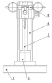
Fig. 1 is front view of the present utility model.
Fig. 2 is side view of the present utility model.
Fig. 3 is the front view of keyway measurement section in the utility model.
Fig. 4 is the side view of keyway measurement section in the utility model.
Mark among the figure: 1, cubing base plate, 2, the mesopore positioning core axle, 3, circumferential locating shaft axle sleeve pair, 4, retreat handle, 5, column, 6, guide rail, 7, raise handle, 8, keyway measurement section, 9, clock gauge, 10, lever seat, 11, measure lever, 12, reversing shaft, 13, spring, 14, steel ball, 15, lever shaft, 16, bulb surveys son, 17, reversing lever, 18, commutation pin, 19, the commutation backing pin.
Embodiment
The utility model, a kind of gear keyway symmetry cubing, its concrete embodiment is:
As shown in the figure, a kind of gear keyway symmetry cubing, mainly by cubing base plate 1, be arranged on the hollow positioning core axle 2 on the cubing base plate, circumferentially locating shaft axle sleeve secondary 3 and column 5 constitute, hollow positioning core axle 2 and circumferential locating shaft axle sleeve secondary 3 are used for the tested gear in location, one end of wherein said circumferential locating shaft axle sleeve pair 3 with retreat handle 4 and be connected, can retreat secondary 3 horizontal directions of the circumferential locating shaft axle sleeve of handle 4 drivings by adjustment moves, be fixed with guide rail 6 in the side of column 5, the top that is positioned at hollow positioning core axle 2 is provided with keyway measurement section 8, keyway measurement section 8 be arranged on the guide rail 6 and with raise handle 7 and be connected, raise handle drives keyway measurement section by adjustment and move back and forth along the guide rail direction;
Described keyway measurement section 8 is mainly by lever seat 10, measure lever 11, lever shaft 15, bulb is surveyed son 16, clock gauge 9, reversing shaft 12 and reversing lever 17 constitute, measure lever 11 by with lever shaft 15 clearance fit, lever shaft 15 is connected on the lever seat 10, reversing shaft 12 cooperates by axis hole and screw is connected on the lever seat 10, one end of reversing shaft 12 is assembled in the commutation hole of measuring lever 11, the other end is connected with reversing lever 17, end at described measurement lever 11 is connected with bulb survey 16, the indicator that measurement lever 11 other ends are provided with 9, two clock gauges 9 of two clock gauges contacts with the two sides of measuring lever 11 respectively.
Also being provided with commutation pin 18 and commutation backing pin 19 in the described keyway measurement section 8, commutation pin 18 is connected on the reversing shaft 12 by the axis hole interference fit, and commutation backing pin 19 is connected on the lever seat 10 by the axis hole interference fit.
Described reversing shaft 12 is assembled in the commutation hole of measuring lever 11, and its gap is 1mm, also is provided with spring 13 and steel ball 14 in the hole of reversing shaft 12.
Workflow of the present utility model is: at first, manually with mesopore positioning core axle and the circumferential locating shaft gear of having good positioning, manually pull then and raise handle, operation keyway measurement section enters in the tested gear keyway along guide rail, left rotation and right rotation reversing lever again, make bulb survey the two sides that son contacts keyway respectively, read two clock gauge readings respectively, two clock gauge reading differences are keyway symmetry actual error value, behind the record data, operate each handle, successively keyway measurement section, circumferential locating shaft are retreated, take out workpiece, operation is finished.
Claims (5)
1. gear keyway symmetry cubing, it is characterized in that: comprise cubing base plate (1), be arranged on the hollow positioning core axle (2) on the cubing base plate, circumferential locating shaft axle sleeve pair (3) and column (5), hollow positioning core axle (2) and circumferential locating shaft axle sleeve pair (3) are used for the tested gear in location, be fixed with guide rail (6) in the side of column (5), the top that is positioned at hollow positioning core axle (2) is provided with keyway measurement section (8), keyway measurement section (8) be arranged on that guide rail (6) is gone up and with raise handle (7) and be connected, raise handle drives keyway measurement section by adjustment and move back and forth along the guide rail direction;
Described keyway measurement section (8) comprises lever seat (10), measure lever (11), lever shaft (15), bulb is surveyed son (16), clock gauge (9), reversing shaft (12) and reversing lever (17), measure lever (11) by with lever shaft (15) clearance fit, lever shaft (15) is connected on the lever seat (10), reversing shaft (12) cooperates by axis hole and screw is connected on the lever seat (10), one end of reversing shaft (12) is assembled in the commutation hole of measuring lever (11), the other end is connected with reversing lever (17), end at described measurement lever (11) is connected with bulb survey (16), measure lever (11) other end and be provided with two clock gauges (9), the indicator of two clock gauges (9) contacts with the two sides of measuring lever (11) respectively.
2. a kind of gear keyway symmetry cubing according to claim 1 is characterized in that: an end of described circumferential locating shaft axle sleeve pair (3) with retreat handle (4) and be connected.
3. a kind of gear keyway symmetry cubing according to claim 2, it is characterized in that: also be provided with commutation pin (18) and commutation backing pin (19) in the described keyway measurement section (8), commutation pin (18) is connected on the reversing shaft (12) by the axis hole interference fit, and commutation backing pin (19) is connected on the lever seat (10) by the axis hole interference fit.
4. a kind of gear keyway symmetry cubing according to claim 3 is characterized in that: described reversing shaft (12) is assembled in the commutation hole of measuring lever (11), and its gap is 1mm.
5. a kind of gear keyway symmetry cubing according to claim 4 is characterized in that: also be provided with spring (13) and steel ball (14) in the hole of described reversing shaft (12).
Priority Applications (1)
| Application Number | Priority Date | Filing Date | Title |
|---|---|---|---|
| CN 201320099223 CN203163669U (en) | 2013-03-05 | 2013-03-05 | Test tool of gear keyway symmetry degree |
Applications Claiming Priority (1)
| Application Number | Priority Date | Filing Date | Title |
|---|---|---|---|
| CN 201320099223 CN203163669U (en) | 2013-03-05 | 2013-03-05 | Test tool of gear keyway symmetry degree |
Publications (1)
| Publication Number | Publication Date |
|---|---|
| CN203163669U true CN203163669U (en) | 2013-08-28 |
Family
ID=49024847
Family Applications (1)
| Application Number | Title | Priority Date | Filing Date |
|---|---|---|---|
| CN 201320099223 Expired - Fee Related CN203163669U (en) | 2013-03-05 | 2013-03-05 | Test tool of gear keyway symmetry degree |
Country Status (1)
| Country | Link |
|---|---|
| CN (1) | CN203163669U (en) |
Cited By (4)
| Publication number | Priority date | Publication date | Assignee | Title |
|---|---|---|---|---|
| CN104501704A (en) * | 2014-10-23 | 2015-04-08 | 洛阳轴研科技股份有限公司 | Device and method for measuring symmetry degree of deep groove ball bearing holder with gap |
| CN105066856A (en) * | 2015-08-19 | 2015-11-18 | 重庆神箭汽车传动件有限责任公司 | Tool for testing degree of symmetry of gear key groove |
| CN108592851A (en) * | 2018-05-04 | 2018-09-28 | 洛阳鹏起实业有限公司 | A kind of workpiece symmetry detecting tool and detection method |
| CN108981642A (en) * | 2018-09-19 | 2018-12-11 | 北京铂阳顶荣光伏科技有限公司 | Axiality detection device and concentricity detection system |
-
2013
- 2013-03-05 CN CN 201320099223 patent/CN203163669U/en not_active Expired - Fee Related
Cited By (5)
| Publication number | Priority date | Publication date | Assignee | Title |
|---|---|---|---|---|
| CN104501704A (en) * | 2014-10-23 | 2015-04-08 | 洛阳轴研科技股份有限公司 | Device and method for measuring symmetry degree of deep groove ball bearing holder with gap |
| CN104501704B (en) * | 2014-10-23 | 2017-07-21 | 洛阳轴研科技股份有限公司 | A kind of measurement device and method of the deep groove ball bearing with breach retainer symmetry |
| CN105066856A (en) * | 2015-08-19 | 2015-11-18 | 重庆神箭汽车传动件有限责任公司 | Tool for testing degree of symmetry of gear key groove |
| CN108592851A (en) * | 2018-05-04 | 2018-09-28 | 洛阳鹏起实业有限公司 | A kind of workpiece symmetry detecting tool and detection method |
| CN108981642A (en) * | 2018-09-19 | 2018-12-11 | 北京铂阳顶荣光伏科技有限公司 | Axiality detection device and concentricity detection system |
Similar Documents
| Publication | Publication Date | Title |
|---|---|---|
| CN204346328U (en) | A kind of cubing of detection axis class part length | |
| CN201909596U (en) | Checking fixture for degree of symmetry | |
| CN203163669U (en) | Test tool of gear keyway symmetry degree | |
| CN203274660U (en) | Special-purpose measuring tool for measuring axis part keyway symmetry degree | |
| CN202329522U (en) | Upper mold planeness detecting device for bending machine | |
| CN104215156A (en) | Key groove reference block and single-hole single and double key groove symmetry degree detector | |
| CN203274632U (en) | A portable length detecting apparatus of shaft parts | |
| CN102778193A (en) | Detection tool with function of automatic centering of workpiece center line | |
| CN103453815A (en) | Gear ring radial runout rapid detector | |
| CN103344167A (en) | Crankshaft semicircular key groove depth detection tool | |
| CN102840815B (en) | Assembled type multifunctional workpiece detector for fitter | |
| CN202928472U (en) | Calibrating device for right angle detection ruler and wedge plug ruler | |
| CN201688794U (en) | Quick position evaluation tool | |
| CN102147224B (en) | Novel measuring tool for overall length of blade | |
| CN203274624U (en) | Circular ring disc body geometric tolerance gauge | |
| CN203116684U (en) | Workpiece end face parallelism detector | |
| CN105066856A (en) | Tool for testing degree of symmetry of gear key groove | |
| CN206258054U (en) | A kind of cubing for detecting disk roller maximum outside diameter | |
| CN201149477Y (en) | Instrument for measuring automatically rear axle housing | |
| CN102997808A (en) | Size measuring tool | |
| CN201764939U (en) | Coaxiality and parallelism check tool for air compressor transmission shaft and fuel pump shaft | |
| CN202974124U (en) | Size measuring tool | |
| CN203824467U (en) | Outer arc intersection point position and bounce measuring tester | |
| CN201876216U (en) | Novel measuring tool for detecting total length of blade | |
| CN203405147U (en) | Measuring tool specially used for detecting stand hole of iron seat |
Legal Events
| Date | Code | Title | Description |
|---|---|---|---|
| C14 | Grant of patent or utility model | ||
| GR01 | Patent grant | ||
| CF01 | Termination of patent right due to non-payment of annual fee |
Granted publication date: 20130828 Termination date: 20140305 |