CN203154893U - Rapid filter tank - Google Patents
Rapid filter tank Download PDFInfo
- Publication number
- CN203154893U CN203154893U CN 201320047203 CN201320047203U CN203154893U CN 203154893 U CN203154893 U CN 203154893U CN 201320047203 CN201320047203 CN 201320047203 CN 201320047203 U CN201320047203 U CN 201320047203U CN 203154893 U CN203154893 U CN 203154893U
- Authority
- CN
- China
- Prior art keywords
- water
- arm
- canal
- communicated
- material layer
- Prior art date
- Legal status (The legal status is an assumption and is not a legal conclusion. Google has not performed a legal analysis and makes no representation as to the accuracy of the status listed.)
- Expired - Fee Related
Links
Images
Abstract
The utility model relates to a rapid filter tank which comprises a tank body, wherein a filter material layer and a support layer are arranged at the bottom of the tank body from top to bottom; a muddy water channel, a wastewater channel and a pipe rack component are arranged outside the tank body; a water distribution system and a flushing drainage tank are arranged in the tank body; the water distribution system is arranged at the lower part of the support layer; and the filter material layer is of a two-layer or three-layer structure. According to the rapid filter tank provided by the utility model, the filter material layer is set as a two-layer or three-layer structure, and the filter speed is higher than that of a single-layer structure; and meanwhile, the dirt containing capacity is great, the working period is long, and the efficiency is high.
Description
Technical field
The utility model relates to a kind of rapid filter.
Background technology
Rapid filter is the most widely used water filtration device of giving, is used for handling the remaining suspension in back except the middle process coagulating sedimentation that anhydrates, or the suspension after the process agglomeration process in the water.Mainly be adopt quartz sand or anthracite, ore equigranular filtrate filters fast to running water and reach the pond of purpose such as suspended solid and part bacterium, microorganism in the trap water.The filtrate of present rapid filter generally adopts the individual layer filtrate, and filtering velocity is slower when adopting the individual layer filtrate, and the valve that equipment arranges is many, and flushing device need be set separately.
The utility model content
The purpose of this utility model is to provide a kind of rapid filter, and this device filtering velocity is fast, the efficient height.
For achieving the above object, the utility model has adopted following technical scheme: comprise the pond body, body bottom, pond from up to down is provided with filter material layer and supporting layer, described pond external body is provided with muddy water canal, waste water canal and piping lane parts, body inside, described pond is provided with water distribution system and wash-water gutter, described water distribution system is arranged on the bottom of supporting layer, and described filter material layer is bilayer or three-decker.
Described filter material layer is double-decker, comprises the anthracite coal measure and the quartzy sand bed that from up to down arrange.
Described filter material layer is three-decker, comprises the anthracite coal measure, quartzy sand bed and the garnet layer that from up to down arrange.
Described piping lane parts comprise the water inlet manifold that from up to down arranges, flushing water house steward and clear water house steward, described water inlet manifold, flushing water house steward and clear water house steward respectively with the water inlet arm, the flushing water arm links to each other with the clear water arm, described water inlet arm, be respectively equipped with first on flushing water arm and the clear water arm, second, the 3rd valve, described water inlet arm is communicated with the muddy water canal, the muddy water canal is communicated with the pond body, described flushing water arm is communicated with the pond body, described clear water arm is communicated with the flushing water arm, and top and muddy water canal bottom that described muddy water canal is arranged on the waste water canal are provided with the draining valve that water is entered the waste water canal.
Described water distribution system comprises many range pipes that are distributed in body bottom, pond, described many range pipes are communicated with distributing main, the outlet of described distributing main is communicated with the flushing water arm, described wash-water gutter is arranged on the top of filter material layer, and the discharge outlet of wash-water gutter is communicated with the muddy water canal.
As shown from the above technical solution, the utility model is by being arranged to filter material layer bilayer or three-decker, and filtering velocity is with respect to the height of single layer structure, and it is bigger to contain dirty ability simultaneously, and the work period is long, the efficient height.
Description of drawings
Fig. 1 is structural representation of the present utility model;
Fig. 2 is the structural representation of the utility model filter material layer embodiment one;
Fig. 3 is the structural representation of the utility model filter material layer embodiment two.
The specific embodiment
Below in conjunction with accompanying drawing the utility model is described further:
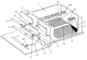
A kind of rapid filter as shown in Figure 1-Figure 3, comprise pond body 1, body 1 bottom in pond from up to down is provided with filter material layer 2 and supporting layer 3, body 1 outside in pond is provided with muddy water canal 4, waste water canal 5 and piping lane parts, body inside, pond is provided with water distribution system and wash-water gutter 92, water distribution system is arranged on the bottom of supporting layer 3, and described filter material layer 2 is bilayer or three-decker.
Embodiment one:
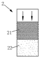
As shown in Figure 2, filter material layer 2 is double-decker, comprises the anthracite coal measure 21 and the quartzy sand bed 22 that from up to down arrange.
Embodiment two:
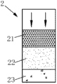
As shown in Figure 3, filter material layer 2 is three-decker, comprises the anthracite coal measure 21, quartzy sand bed 22 and the garnet layer 23 that from up to down arrange.
Further, the piping lane parts comprise the water inlet manifold 6 that from up to down arranges, flushing water house steward 7 and clear water house steward 8, water inlet manifold 6, flushing water house steward 7 and clear water house steward 8 respectively with the water inlet arm 61, flushing water arm 71 links to each other with clear water arm 81, water inlet arm 61, be respectively equipped with first on flushing water arm 71 and the clear water arm 81, second, the 3rd valve 62,72,82, water inlet arm 61 is communicated with muddy water canal 4, muddy water canal 4 is communicated with pond body 1, flushing water arm 71 is communicated with pond body 1, clear water arm 81 is communicated with flushing water arm 71, and top and muddy water canal 4 bottoms that muddy water canal 4 is arranged on waste water canal 5 are provided with the draining valve 41 that water is entered waste water canal 5.
Water distribution system comprises the many range pipes 9 that are distributed in pond body 1 bottom, many range pipes 9 are communicated with distributing main 91, the outlet of distributing main 91 is communicated with flushing water arm 71, and wash-water gutter 92 is arranged on the top of filter material layer 2, and the discharge outlet of wash-water gutter 92 is communicated with muddy water canal 4.
The concrete course of work is as follows:
When a kind of rapid filter filters, open the first, the 3rd valve 62,82 on water inlet arm 61 and the clear water arm 81, this moment, muddy water entered pond body 1 through water inlet manifold 6, water inlet arm 61, muddy water canal 4, the water that enters pond body 1 is after filtration behind the bed of material 2, the supporting layer 3, compile at range pipe 9, flow to clear water reserviors through distributing main 91, clear water arm 81, clear water house steward 8 again; When a kind of rapid filter carries out backwash; close first valve 61 on the water arm 61 into; when dropping to the above about 20cm of sand face Deng water level; close the 3rd valve 82 on the clear water arm 81 again; second valve 72 on opening water discharge valve 41 and the flushing water arm 71; flushing water namely by flushing water house steward 7 through flushing water arm 71; through the water distribution system edge direction opposite with filtration; be distributed in equably on the body plane of whole pond; filter material layer 2 gets up at equally distributed flow action low suspension from bottom to top; and progressively expand into certain altitude; filtering material particle runs foul of each other; friction, the impurity such as mud that are attached on the filter material surface just split away off, the waste water draining wash-water gutter 92 after the flushing; again through muddy water canal 4; draining valve 41 enters waste water canal 5 and enters sewer, till the water of discharging is comparatively limpid.
Above-described embodiment is described preferred embodiment of the present utility model; be not that scope of the present utility model is limited; under the prerequisite that does not break away from the utility model design spirit; various distortion and improvement that those of ordinary skills make the technical solution of the utility model all should fall in the definite protection domain of the utility model claims.
Claims (5)
1. rapid filter, it is characterized in that: comprise pond body (1), pond body (1) bottom from up to down is provided with filter material layer (2) and supporting layer (3), described pond body (1) outside is provided with muddy water canal (4), waste water canal (5) and piping lane parts, body inside, described pond is provided with water distribution system and wash-water gutter (92), described water distribution system is arranged on the bottom of supporting layer (3), and described filter material layer (2) is bilayer or three-decker.
2. a kind of rapid filter according to claim 1, it is characterized in that: described filter material layer (2) is double-decker, comprises the anthracite coal measure (21) and the quartzy sand bed (22) that from up to down arrange.
3. a kind of rapid filter according to claim 1 is characterized in that: described filter material layer (2) is three-decker, comprises the anthracite coal measure (21), quartzy sand bed (22) and the garnet layer (23) that from up to down arrange.
4. a kind of rapid filter according to claim 1, it is characterized in that: described piping lane parts comprise the water inlet manifold (6) that from up to down arranges, flushing water house steward (7) and clear water house steward (8), described water inlet manifold (6), flushing water house steward (7) and clear water house steward (8) respectively with the water inlet arm (61), flushing water arm (71) links to each other with clear water arm (81), described water inlet arm (61), be respectively equipped with first on flushing water arm (71) and the clear water arm (81), second, the 3rd valve (62,72,82), described water inlet arm (61) is communicated with muddy water canal (4), muddy water canal (4) is communicated with pond body (1), described flushing water arm (71) is communicated with pond body (1), described clear water arm (81) is communicated with flushing water arm (71), and top and muddy water canal (4) bottom that described muddy water canal (4) is arranged on waste water canal (5) are provided with the draining valve (41) that water is entered waste water canal (5).
5. a kind of rapid filter according to claim 4, it is characterized in that: described water distribution system comprises the many range pipes (9) that are distributed in pond body (1) bottom, described many range pipes (9) are communicated with distributing main (91), the outlet of described distributing main (91) is communicated with flushing water arm (71), described wash-water gutter (92) is arranged on the top of filter material layer (2), and the discharge outlet of wash-water gutter (92) is communicated with muddy water canal (4).
Priority Applications (1)
| Application Number | Priority Date | Filing Date | Title |
|---|---|---|---|
| CN 201320047203 CN203154893U (en) | 2013-01-29 | 2013-01-29 | Rapid filter tank |
Applications Claiming Priority (1)
| Application Number | Priority Date | Filing Date | Title |
|---|---|---|---|
| CN 201320047203 CN203154893U (en) | 2013-01-29 | 2013-01-29 | Rapid filter tank |
Publications (1)
| Publication Number | Publication Date |
|---|---|
| CN203154893U true CN203154893U (en) | 2013-08-28 |
Family
ID=49016118
Family Applications (1)
| Application Number | Title | Priority Date | Filing Date |
|---|---|---|---|
| CN 201320047203 Expired - Fee Related CN203154893U (en) | 2013-01-29 | 2013-01-29 | Rapid filter tank |
Country Status (1)
| Country | Link |
|---|---|
| CN (1) | CN203154893U (en) |
Cited By (2)
| Publication number | Priority date | Publication date | Assignee | Title |
|---|---|---|---|---|
| CN106823538A (en) * | 2016-12-28 | 2017-06-13 | 芜湖顺景自动化设备有限公司 | A kind of high efficiency particulate air filter equipment with anticorrosive coat |
| CN106823502A (en) * | 2017-03-15 | 2017-06-13 | 山东问清环境科技有限公司 | A kind of automatic pump of valveless gate control rinses sand filter |
-
2013
- 2013-01-29 CN CN 201320047203 patent/CN203154893U/en not_active Expired - Fee Related
Cited By (2)
| Publication number | Priority date | Publication date | Assignee | Title |
|---|---|---|---|---|
| CN106823538A (en) * | 2016-12-28 | 2017-06-13 | 芜湖顺景自动化设备有限公司 | A kind of high efficiency particulate air filter equipment with anticorrosive coat |
| CN106823502A (en) * | 2017-03-15 | 2017-06-13 | 山东问清环境科技有限公司 | A kind of automatic pump of valveless gate control rinses sand filter |
Similar Documents
| Publication | Publication Date | Title |
|---|---|---|
| CN102774896B (en) | Integral purification device and method for particles in rain and sewage | |
| CN103285661B (en) | The equipment for separating liquid from solid of waste water suspension | |
| CN206660759U (en) | Vertical sedimentation basin | |
| CN105330069A (en) | Air flotation and filtering device | |
| CN203208732U (en) | Sand trap | |
| CN203154893U (en) | Rapid filter tank | |
| CN203291633U (en) | Solid-liquid separating device for waste water suspended solids | |
| CN201578891U (en) | Novel sand filter | |
| CN202876533U (en) | Wastewater treatment system for coal mine equipment | |
| CN101564616A (en) | Blast furnace slag flushing water purification system and method thereof | |
| CN105712582A (en) | Reverse-size deep bed filter pool applied to sewage treatment plant upgrading and reconstruction | |
| CN201292297Y (en) | Integral water purifier | |
| CN102188849B (en) | Back-flushing device of ceramic filtering plate | |
| CN207694317U (en) | A kind of clarifying basin | |
| CN103449665B (en) | A kind of polluted water land biogenic sediment filtering system for mud-water separation | |
| CN105233562A (en) | Iron sheet dewatering pool | |
| CN209405838U (en) | A kind of solid-liquid separation system for liquid waste processing | |
| CN207451792U (en) | A kind of effective integrated sewage disposal device | |
| CN102786185A (en) | Ecological northern alkaline mine water treatment system and ecological northern alkaline mine water treatment method | |
| CN202170256U (en) | Novel scum filtering-type air flotation filter equipment | |
| CN208182803U (en) | Suspension filter subsurface flow wetland system | |
| CN105056623B (en) | A kind of high-efficiency sewage treating column | |
| CN207330399U (en) | A kind of anti-race sand device in sewage disposal V-type filter tank | |
| CN201660481U (en) | Cyclone-flocculation water purifier | |
| CN206244623U (en) | A kind of glass toughening manure pit |
Legal Events
| Date | Code | Title | Description |
|---|---|---|---|
| C14 | Grant of patent or utility model | ||
| GR01 | Patent grant | ||
| CF01 | Termination of patent right due to non-payment of annual fee |
Granted publication date: 20130828 Termination date: 20210129 |
|
| CF01 | Termination of patent right due to non-payment of annual fee |