CN203150323U - Automatic tape-winding machine - Google Patents
Automatic tape-winding machine Download PDFInfo
- Publication number
- CN203150323U CN203150323U CN 201320147903 CN201320147903U CN203150323U CN 203150323 U CN203150323 U CN 203150323U CN 201320147903 CN201320147903 CN 201320147903 CN 201320147903 U CN201320147903 U CN 201320147903U CN 203150323 U CN203150323 U CN 203150323U
- Authority
- CN
- China
- Prior art keywords
- winding
- slide block
- adhesive plaster
- automatic apparatus
- screw mandrel
- Prior art date
- Legal status (The legal status is an assumption and is not a legal conclusion. Google has not performed a legal analysis and makes no representation as to the accuracy of the status listed.)
- Expired - Fee Related
Links
Images
Landscapes
- Manufacture Of Motors, Generators (AREA)
Abstract
This utility model discloses an automatic tape-winding machine, which comprises a horizontal linear drive device provided on a base, a sliding block provided with a motor and a winding mechanism, and clamping mechanisms provided on two sides of the sliding block. A wire hole goes through the winding mechanism; the horizontal liner drive device drives the sliding block move back and forth between the clamping mechanisms; the motor drives the winding mechanism to rotate around the wire hole and the winding wire is fixed on the clamping mechanism after the winding wire goes through the wire hole. This utility model has advantages of simple structure, easy use, and high working efficiency. Furthermore, the tape-winding machine can wind tape around the cable without assistance of an operator.
Description
Technical field
The utility model relate to a kind of simple in structure, convenient and practical, need not operating personnel and assist the automatic Apparatus for winding adhesive plaster operated.
Background technology
When need be when lead be wrapped with adhesive plaster for electrostatic screen, often need the operator by hand adhesive plaster to be wrapped on the lead, this method efficient is low, labour intensity is big, loses time very much, influenced greatly by human factor, it is inhomogeneous that adhesive plaster pastes, influence attractive in appearancely, product quality is poor, also is not suitable for the specialized large-scale production of factory.
In order to solve the inconvenience that brings owing to manual operation, people have invented a kind of Apparatus for winding adhesive plaster, number be CN2926148Y as Chinese patent literature, this is a kind of synchronizing shaft bearing structure and the semi-automatic winding adhesive tape machine that uses this synchronizing shaft bearing structure, the synchronizing shaft bearing structure, comprise a bearing, be sheathed on the sleeve on the bearing, bearing is a polygonal bearing, and sleeve has many interior angles, arranges with the bearing coupling, the fixing company one of one end of bearing has the anchor clamps of round extension folder, the outside sheathed gear of sleeve.Semi-automatic winding adhesive tape machine has a workbench, and from the two ends decibel of this workbench extended supporting seat, Bearning mechanism is separately positioned on the supporting seat synchronously, one of them synchronizing shaft bearing structure will be connected with a drive link with variable speed electric motors, particularly by a belt, and another synchronous Bearning mechanism is connected with drive link by belt.
This method is compared with manual operations, in production efficiency and product quality the raising of arriving has been arranged very much, but there is a problem in this method, needs operating personnel to assist operation, thereby reaches the purpose of winding, produces inconvenient.Therefore, being necessary that development and Design is a kind of does not need operating personnel to hold adhesive plaster with hand or other things, just finishes to twining one deck adhesive plaster Apparatus for winding adhesive plaster again such as lead or other cable outsides, to increase work efficiency automatically.
The utility model content
The purpose of this utility model is at the problems referred to above, provides a kind of operating personnel of need not to assist the automatic Apparatus for winding adhesive plaster of operating to society.
The technical solution of the utility model is: design a kind of automatic Apparatus for winding adhesive plaster, comprise the horizontal linear drive unit that is arranged on the base, be provided with the slide block of motor and winding mechanism, and be arranged on the clamp system of described slide block both sides, described winding mechanism and described slide block are run through in one line hole, described horizontal linear drive unit drives described slide block and moves around between described clamp system, the described winding mechanism of described motor-driven rotatablely moves centered by described line hole, and cable to be wound passes described line hole and is fixed on the described clamp system.
As to improvement of the present utility model, described winding mechanism comprises more than one winding arm, and described winding arm is provided with the immobilization with adhesive tape frame, and described winding arm becomes the obtuse angle with cable to be wound.
As to improvement of the present utility model, described clamp system comprises location-plate and anchor clamps, and described anchor clamps are arranged on the described location-plate, and described location-plate is arranged on the base support.
As to improvement of the present utility model, comprise that also two ends are arranged on the guide pillar on the described base support, described slide block is arranged on the guide column sleeve.
As to improvement of the present utility model, comprise that also two ends are arranged on the screw mandrel on the described base support, described slide block moves around at described screw mandrel, and the described screw mandrel of described slide block both sides is provided with transducer.
As to improvement of the present utility model, described screw mandrel can replace with polished rod.
As to improvement of the present utility model, described horizontal linear drive unit replaces with cylinder, hydraulic cylinder or electric work cylinder.
The utlity model has simple in structure, convenient and practical, high efficiency and need not operating personnel and assist to operate the advantage that just adhesive plaster can be wrapped on the cable.
Description of drawings
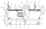
Fig. 1 is the perspective view of a kind of embodiment of the utility model.
Wherein: 1. base; 2. base support; 3. cylinder; 31. cylinder guide rod; 4. slide block; 41. line hole; 5. winding mechanism; 51. winding arm; 52. immobilization with adhesive tape frame; 6. motor; 7. clamp system; 71. location-plate; 72. anchor clamps; 8. guide pillar; 81. guide column sleeve; 9. screw mandrel; 91. transducer.
Embodiment
See also Fig. 1, what Fig. 1 disclosed is a kind of automatic Apparatus for winding adhesive plaster, comprise the cylinder 3 that is arranged on the base 1, be provided with the slide block 4 of motor 6 and winding mechanism 5, and be arranged on the clamp system 7 of described slide block 4 both sides, described winding mechanism 5 and described slide block 4 are run through in one line hole 41, described slide block is arranged on the described cylinder 3, described cylinder 3 move around at cylinder guide rod 31 (described cylinder 3 drives described slide block 4 and moves around between described clamp system 7), described motor 6 drives described winding mechanism 5 and rotatablely moves centered by described line hole 41, and cable to be wound passes described line hole 41 and is fixed on the described clamp system 7.
In the present embodiment, described winding mechanism 5 comprises the winding arm 51 of two symmetrical distributions, and described winding arm 51 is provided with immobilization with adhesive tape frame 52, and described winding arm 51 becomes the obtuse angle with cable to be wound.The quantity of described winding arm 51 can be one or more.Described clamp system 7 comprises location-plate 71 and anchor clamps 72, and described anchor clamps 72 are arranged on the described location-plate 71, and described location-plate 71 is arranged on the base support 2.The two ends of guide pillar 8 are arranged on the described base support 2, and described slide block 4 is arranged on the guide column sleeve 81.
In the present embodiment, comprise that also two ends are arranged on the screw mandrel 9 on the described base support 2, described slide block 4 moves around at described screw mandrel 9, and the described screw mandrel 9 of described slide block 4 both sides is provided with transducer 91.Described screw mandrel 9 can replace with polished rod.Described cylinder 3 can replace with hydraulic cylinder or electric work cylinder.
In the present embodiment, cable to be wound passes described line hole 41, be fixed on the described location-plate 71 by described anchor clamps 72, fixing glue yardage roll on described immobilization with adhesive tape frame 52, one end of the adhesive plaster on the adhesive plaster volume is wrapped on the cable to be wound, described cylinder 3 drives described slide block 4 and moves described winding mechanism 5 rotations of simultaneously described motor 6 drivings then.When described slide block 4 touches described transducer 91, described transducer 91 sends to control cabinet (this figure omits) with signal, described control cabinet will transmit control signal to described motor 6 and described cylinder 3, described motor 6 and described cylinder 3 will quit work, operating personnel cut off adhesive plaster with scissors in the place that does not have to twine, take off the cable that winds from described anchor clamps 72 then.Operate the control switch of described control cabinet, described cylinder 3 drives described slide block 4 and gets back to the position that begins to twine.
The utlity model has simple in structure, convenient and practical, high efficiency and need not operating personnel and assist to operate the advantage that just adhesive plaster can be wrapped on the cable.
Claims (7)
1. automatic Apparatus for winding adhesive plaster, it is characterized in that, comprise the horizontal linear drive unit that is arranged on the base, be provided with the slide block of motor and winding mechanism, and be arranged on the clamp system of described slide block both sides, described winding mechanism and described slide block are run through in one line hole, described horizontal linear drive unit drives described slide block and moves around between described clamp system, the described winding mechanism of described motor-driven rotatablely moves centered by described line hole, and cable to be wound passes described line hole and is fixed on the described clamp system.
2. automatic Apparatus for winding adhesive plaster as claimed in claim 1, it is characterized in that: described winding mechanism comprises more than one winding arm, and described winding arm is provided with the immobilization with adhesive tape frame, and described winding arm becomes the obtuse angle with cable to be wound.
3. automatic Apparatus for winding adhesive plaster as claimed in claim 1 or 2, it is characterized in that: described clamp system comprises location-plate and anchor clamps, and described anchor clamps are arranged on the described location-plate, and described location-plate is arranged on the base support.
4. automatic Apparatus for winding adhesive plaster as claimed in claim 1 or 2, it is characterized in that: comprise that also two ends are arranged on the guide pillar on the described base support, described slide block is arranged on the guide column sleeve.
5. automatic Apparatus for winding adhesive plaster as claimed in claim 1 or 2, it is characterized in that: comprise that also two ends are arranged on the screw mandrel on the described base support, described slide block moves around at described screw mandrel, and the described screw mandrel of described slide block both sides is provided with transducer.
6. automatic Apparatus for winding adhesive plaster as claimed in claim 5, it is characterized in that: described screw mandrel can replace with polished rod.
7. automatic Apparatus for winding adhesive plaster as claimed in claim 1 or 2 is characterized in that: described horizontal linear drive unit cylinder, hydraulic cylinder or the replacement of electric work cylinder.
Priority Applications (1)
| Application Number | Priority Date | Filing Date | Title |
|---|---|---|---|
| CN 201320147903 CN203150323U (en) | 2013-03-28 | 2013-03-28 | Automatic tape-winding machine |
Applications Claiming Priority (1)
| Application Number | Priority Date | Filing Date | Title |
|---|---|---|---|
| CN 201320147903 CN203150323U (en) | 2013-03-28 | 2013-03-28 | Automatic tape-winding machine |
Publications (1)
| Publication Number | Publication Date |
|---|---|
| CN203150323U true CN203150323U (en) | 2013-08-21 |
Family
ID=48977832
Family Applications (1)
| Application Number | Title | Priority Date | Filing Date |
|---|---|---|---|
| CN 201320147903 Expired - Fee Related CN203150323U (en) | 2013-03-28 | 2013-03-28 | Automatic tape-winding machine |
Country Status (1)
| Country | Link |
|---|---|
| CN (1) | CN203150323U (en) |
Cited By (2)
| Publication number | Priority date | Publication date | Assignee | Title |
|---|---|---|---|---|
| CN107196179A (en) * | 2017-06-02 | 2017-09-22 | 芜湖博康机电有限公司 | A kind of automotive wire bundle flowing water twines adhesive tape technique |
| CN107293926A (en) * | 2017-06-02 | 2017-10-24 | 芜湖博康机电有限公司 | A kind of improvement type twines adhesive tape workbench |
-
2013
- 2013-03-28 CN CN 201320147903 patent/CN203150323U/en not_active Expired - Fee Related
Cited By (4)
| Publication number | Priority date | Publication date | Assignee | Title |
|---|---|---|---|---|
| CN107196179A (en) * | 2017-06-02 | 2017-09-22 | 芜湖博康机电有限公司 | A kind of automotive wire bundle flowing water twines adhesive tape technique |
| CN107293926A (en) * | 2017-06-02 | 2017-10-24 | 芜湖博康机电有限公司 | A kind of improvement type twines adhesive tape workbench |
| CN107196179B (en) * | 2017-06-02 | 2019-02-01 | 芜湖博康机电有限公司 | A kind of automotive wire bundle flowing water twines adhesive tape technique |
| CN107293926B (en) * | 2017-06-02 | 2019-04-26 | 芜湖博康机电有限公司 | A kind of improvement type twines adhesive tape workbench |
Similar Documents
| Publication | Publication Date | Title |
|---|---|---|
| CN207258897U (en) | A kind of bobbin winder device | |
| CN202622453U (en) | Synchronous feeding and measuring device for cutting machine | |
| CN211733412U (en) | End shaft type cable creel stand | |
| CN203150323U (en) | Automatic tape-winding machine | |
| CN204304733U (en) | Coil winding machine | |
| CN204310561U (en) | A kind of adhesive tape up-coiler | |
| CN208667478U (en) | A kind of mechanical glass rectangle cutting equipment | |
| CN203751467U (en) | Electric discharge wire cutting, winding and tensioning device | |
| CN202480368U (en) | Twining device for adhesive tape of wires | |
| CN204953565U (en) | Inverse -vertical wire wrapping machine | |
| CN208802688U (en) | A kind of coil winding machine | |
| CN205016374U (en) | Self -adhesion coil spooling equipment | |
| CN209242391U (en) | Body of rod winding mechanism | |
| CN208150664U (en) | Cable twines device again | |
| CN104444534B (en) | A kind of rope net antenna wire cutting machine | |
| CN212863538U (en) | A spiral equipment for wire and cable production | |
| CN109110568A (en) | A kind of coil winding machine | |
| CN103112758B (en) | Finished cable wrap-up | |
| CN214586097U (en) | Cutting device is used in processing of optic fibre optical cable | |
| CN104444498A (en) | Adhesive tape winding machine | |
| CN114590635A (en) | Pay-off device for laying power transmission line | |
| CN109110567A (en) | A kind of cable wind convenient to use | |
| CN204953564U (en) | Automatic handstand formula admission machine | |
| CN203845574U (en) | Winding mechanism for optical fiber winding machine | |
| CN202626020U (en) | Pin bending machine for spiral tube of energy-saving lamp |
Legal Events
| Date | Code | Title | Description |
|---|---|---|---|
| C14 | Grant of patent or utility model | ||
| GR01 | Patent grant | ||
| CF01 | Termination of patent right due to non-payment of annual fee |
Granted publication date: 20130821 |
|
| CF01 | Termination of patent right due to non-payment of annual fee |