CN203147717U - Steam generation device with CPC (Compound Parabolic Concentrator) solar concentrator collectors - Google Patents
Steam generation device with CPC (Compound Parabolic Concentrator) solar concentrator collectors Download PDFInfo
- Publication number
- CN203147717U CN203147717U CN2013200613054U CN201320061305U CN203147717U CN 203147717 U CN203147717 U CN 203147717U CN 2013200613054 U CN2013200613054 U CN 2013200613054U CN 201320061305 U CN201320061305 U CN 201320061305U CN 203147717 U CN203147717 U CN 203147717U
- Authority
- CN
- China
- Prior art keywords
- thermal
- arrest medium
- arrest
- steam generator
- cpc
- Prior art date
- Legal status (The legal status is an assumption and is not a legal conclusion. Google has not performed a legal analysis and makes no representation as to the accuracy of the status listed.)
- Withdrawn - After Issue
Links
Images


Classifications
-
- Y—GENERAL TAGGING OF NEW TECHNOLOGICAL DEVELOPMENTS; GENERAL TAGGING OF CROSS-SECTIONAL TECHNOLOGIES SPANNING OVER SEVERAL SECTIONS OF THE IPC; TECHNICAL SUBJECTS COVERED BY FORMER USPC CROSS-REFERENCE ART COLLECTIONS [XRACs] AND DIGESTS
- Y02—TECHNOLOGIES OR APPLICATIONS FOR MITIGATION OR ADAPTATION AGAINST CLIMATE CHANGE
- Y02E—REDUCTION OF GREENHOUSE GAS [GHG] EMISSIONS, RELATED TO ENERGY GENERATION, TRANSMISSION OR DISTRIBUTION
- Y02E10/00—Energy generation through renewable energy sources
- Y02E10/40—Solar thermal energy, e.g. solar towers
- Y02E10/44—Heat exchange systems
Abstract
The utility model discloses a steam generation device with CPC solar concentrator collectors. The steam generation device with the CPC solar concentrator collectors comprises a collector group and a steam generator and is mainly characterized in that medium input pipe orifices and medium output pipe orifices of the CPC solar concentrator collectors are connected with an input connecting box pipeline and an output connecting box pipeline; an electric heater is arranged inside an energy storage box; a liquid pump is arranged on a main medium input pipeline and a medium input pipeline of heat collection medium heat exchangers respectively; the heat exchangers are spiral coil heat exchangers; the condensers of the heat collection spiral coil heat exchangers are back surface mirrors, the back surfaces of glass bases of the back surface mirrors are plated with reflective film layers and protective film layers, and the back surfaces of the back surface mirrors are integrally connected with matrix glass in an adhesive mode; and glass cover plates are respectively arranged on notches and open ends on two sides of the groove type condensers. The steam generation device with the CPC solar concentrator collectors has the advantages of being reasonable in structural configuration, high in reflectance of the condensers, good in heat utilization effect, long in service life and the like.
Description
Technical field
The utility model relates to a kind of steam raising plant of the CPC of employing solar concentrating collector, belongs to solar energy utilization technique device field.
Background technology
CPC described in the utility model is the abbreviation of English Compound Parabolic Concentrator, and the meaning is compound parabolic concentrator collector.It is the unique a kind of high-effective concentration heat collector that does not need the Continuous Tracking sun in the concentrating collector.Only need the inclination angle of 2 ~ 4 adjustment heat collectors in 1 year, just can obtain maximum light harvesting ratio.
And described steam raising plant adopts the CPC solar concentrating collector exactly, heat energy is provided and produces the steam raising plant of steam.
Described this steam raising plant, can supply industrial and mining enterprises, hotel and outdoor bathing place and residential quarter etc. such as decatize food (meal, steamed bun and dish), boil water, take a shower, heat and refrigeration etc. is many-sided uses, also can be light industry such as textile industry, chemical industry, papermaking and timber processing, the steam of Chinese herbal medicine processing bakes and aspects such as processing medium and agricultural booth heating, and thermal source steam is provided.Because this steam generator, have the sustainable exploitation of the energy and use, characteristics such as low-carbon environment-friendly and production of steam cost are low, and cause the great attention of Technological Economy circle.
At present, though part universities and colleges are arranged, R﹠D institution and business entity, temperature (100 ~ 200 ℃) steam raising plant in the steam raising plant conduct of proposition employing CPC concentrating collector, be used for steamed rice, the imagination that boils water, and did the trial of model experiment, but eventually because the compound parabolic face condenser of concentrating collector, though adopted formed glass steel substrate surface pad pasting mode, but its reflecting rate unsatisfactory (≤80%) and its be practical be worth not high, and because the weatherability of formed glass base steel is poor, process is hard on, and preparation cost is high and service life is short (general≤2.5 years), and society is difficult to accept.
Chinese patent 200410064610.4 disclosed " composite parabolic light focusing type solar rice cooker device ", adopt moulding surface of aluminum plate pottery treatment technology, the condenser (speculum) of prepared CPC concentrating collector, successfully improved reflecting rate (80 ~ 85%), and 12 kilowatts of CPC solar rice cooker devices (boiler) have been developed in concrete enforcement.At solar irradiation 〉=900W/m
2Under the condition, can steam twice rice (steamed bun) in one day 6 ~ 7 hours.Each 50kg.For the extensive use of the solar rice cooker device that adopts the CPC concentrating collector, opened up a new road, the demoncal ration case is provided.
Yet, take a broad view of described patent (application) technology, still exist many structural deficiencies, select its main having: the one, the reflecting rate of its condenser (front surface mirror) is still lower, so that its solar thermal utilization rate is not high; The 2nd, because its condenser (reflective mirror) is front surface mirror, and be laid in the reflective film of condenser front surface, face the nature adverse circumstances directly, this is not only destroyed and cause the decline of reflecting rate extremely easily, and its normal useful life is also directly had a strong impact on; The 3rd, in the thermal-arrest media flow loop of its total system, delivery outlet and the input port of the thermal-arrest metal clad pipe that is located at the structure that takes the shape of the letter U in the glass tube with vacuum of heat collector, both directly are connected with thermal-arrest medium input house steward pipeline with thermal-arrest medium delivery trunk respectively, this can increase the resistance of medium output and the medium input of heat collector undoubtedly, but also can form the turbulent flow of thermal-arrest medium, so that the operation of thermal-arrest medium circulation has some setbacks, and influences the heat exchange effect of Heat-collecting effect and the thermal-arrest medium heat exchanger of heat collector; Especially not enough is the configuration deficiency of circulating pump, also can influence Heat-collecting effect and heat exchange effect, so that the steam generator steam production is undesirable; The 4th, though it is provided with the medium storage tank in the media flow loop, but the function that its storage tank is undertaken is very simple, especially do not possess electric heating function, thereby can't be competent at the work of steaming at rainy weather or night, and make troubles for application entity of the present utility model; The 5th, though its overall structure can be finished the work of steaming, it lacks automaton, thereby execute-in-place seems that ten minutes bothers.
Summary of the invention
The purpose of this utility model is to provide a kind of system configuration reasonable, the condenser reflecting rate height of heat collector, Heat-collecting effect is good, a kind of steam raising plant that adopts the CPC solar concentrating collector of long service life, overcome the deficiency of prior art, be the extensive use of solar thermal utilization at people's sphere of life and workers and peasants' production field, equipment support is provided.
The utility model is realized the technical though of its purpose, be at the existing many deficiencies of prior art, carry out technological improvement: the one, with the medium input mouth of pipe and the medium output mouth of pipe of the collector metal pipe of heat collector, be connected with the company's case (liquid storage voltage stabilizing bag) with big volume respectively, and then be connected with medium input house steward pipeline with heat collector group's medium delivery trunk respectively by connecting case, thereby effectively reduce the resistance that the thermal-arrest medium flowed into and flowed out the collector metal pipe of heat collector, it is smooth and easy to cause the thermal-arrest medium to move circulation in the loop; The 2nd, in the energy storage case, electric heater is set, change its configuration in the thermal-arrest medium loop simultaneously, round-the-clock with the vapour entity to adapt to, use the needs of vapour continuously over a long time; The 3rd, on the thermal-arrest medium intake line of steam generator, increase by 1 liquid pump, with the motion-promotion force of effective increasing thermal-arrest medium in its steam generator circuits, improve the heat exchange effect of heat exchanger; The 4th, the condenser of heat collector is improved to back surface mirror by front surface mirror, namely in its rear surface plating cloth reflexed light film and protective film, and the rear surface of condenser is integral by adhesive linkage and substrate glass compound sticking, thereby make the reflective film of condenser, be arranged between the laminated glass, effectively avoid natural environment to the injury of reflective film, further improve and keep the reflecting rate of condenser; The 5th, at notch and the and arranged on left and right sides openend of the condenser of the structure that takes the shape of the letter U of heat collector, the cover-plate glass that is coated with sunshine high antireflection film layer and automatically cleaning rete is set respectively, to reduce the heat radiation in the heat collector slot light collection mirror groove, further protect the safety of condenser; The 6th, on the basis that the above technical measures is implemented, increase automaton, to relevant working link of the present utility model, implement control automatically, thereby realize the purpose of this utility model.
Based on the above technical though, the utility model realizes that the technical scheme of its purpose is:
A kind of steam raising plant that adopts the CPC solar concentrating collector, it comprises: have CPC condenser solar concentrating collector spaced apart by several and arrange the heat collector group who forms and the steam generator with thermal-arrest medium heat exchanger; The thermal-arrest medium input mouth of pipe of the collector metal pipe that is located at the structure that takes the shape of the letter U in the glass tube with vacuum of all CPC concentrating collectors of described heat collector group and the thermal-arrest medium output mouth of pipe thereof are connected with thermal-arrest medium delivery trunk pipeline with heat collector group's thermal-arrest medium input house steward respectively; By heat exchanger the water that is present in the steam generator casing is heated, and generate steam; In the thermal-arrest medium loop, be provided with energy storage case and first liquid pump, and its:
A, the thermal-arrest medium of the described CPC concentrating collector input mouth of pipe and the thermal-arrest medium output mouth of pipe thereof be to connect case by input pipe respectively and efferent duct connects case, and be connected with thermal-arrest medium delivery trunk pipeline with thermal-arrest medium input house steward respectively;
B, described energy storage case is provided with heater; Described energy storage case is arranged in the rear of steam generator; Described heat collector group's thermal-arrest medium delivery trunk and thermal-arrest medium input house steward thereof, import respectively in the energy storage case, and the outlet of thermal-arrest medium delivery trunk is positioned at the top of energy storage case, thermal-arrest medium input house steward's entrance, be positioned at the bottom of energy storage case, thereby constitute heat collector group's the big loop of thermal-arrest medium; And the thermal-arrest medium input pipe of the thermal-arrest medium heat exchanger of steam generator, and thermal-arrest medium efferent duct, introduce respectively in the energy storage case, and the entrance of thermal-arrest medium input pipe is positioned at the top of energy storage case, the outlet of thermal-arrest medium efferent duct, be positioned at the bottom of energy storage case, thereby constitute the thermal-arrest medium minor loop of steam generator;
C also comprises second liquid pump (circulating pump); Described first liquid pump is arranged on heat collector group's the thermal-arrest medium input house steward pipeline of contiguous energy storage case, and second liquid pump is arranged on the thermal-arrest medium input pipe pipeline of thermal-arrest medium heat exchanger of steam generator; Make thermal-arrest medium shuttling movement in big loop of heat collector group by first liquid pump, and make thermal-arrest medium shuttling movement in minor loop of steam generator by second liquid pump;
D, described thermal-arrest medium heat exchanger is the spiral coil heat exchanger, and its thermal-arrest medium input port is in the centre of spiral coil, and its thermal-arrest medium delivery outlet is in the outermost of spiral coil, and is connected with thermal-arrest medium efferent duct pipeline with thermal-arrest medium input pipe respectively; Thereby constitute spiral coil shell-side boiling heat transfer; And described spiral coil heat exchanger is 1 at least, when the spiral coil heat exchanger has when a plurality of, then a plurality of spiral coil heat exchangers are evenly arranged in the steam generator casing, and are connected with thermal-arrest medium efferent duct branch line with thermal-arrest medium input pipe by pipe joint respectively;
E, the cpc slot light collection mirror of described solar concentrating collector is arranged by bilateral symmetry, is connected with the parabolic segment transition and the slot type surface mirror and the substrate glass that constitute the structure that takes the shape of the letter U formed by the involute section; Described surface mirror is back surface mirror, and in the rear surface of surface mirror glass-based, plating is furnished with reflexed light film and protective film successively from the inside to the outside; The rear surface of described surface mirror is integral by adhesive layer and substrate glass compound sticking and constitutes CPC slot light collection mirror;
F also comprises the notch end that is closely contacted on described slot light collection mirror respectively and cover-plate glass and the side glass cover-plate of both-side opening end, by cover-plate glass and both sides side glass cover-plate, makes to be full closeding state by the CPC slot light collection mirror of structure of taking the shape of the letter U.
By above given technical scheme, realize that in conjunction with the utility model the technical though of its purpose can be understood, the utility model has been realized the purpose of its required realization.
Based on convenient described with the consideration of vapour entity long-time continuous with vapour, the utility model also comprises the automaton with automatic controller; Described automaton, comprise: automatic controller, be located at first magnetic valve of heat collector group's thermal-arrest medium delivery trunk downstream portion, be located at first temperature sensor in the energy storage case, be located at second temperature sensor in the steam generator, be located at second magnetic valve on steam generator and the city public water water source attaching pipeline, be located at the level sensor in the steam generator casing, be located at the 3rd magnetic valve on the medium efferent duct pipeline of thermal-arrest medium heat exchanger and be located at flow sensor on the steam output pipe road on the steam generator casing top; Described first magnetic valve, first temperature sensor, second temperature sensor, second magnetic valve, level sensor, the 3rd magnetic valve, flow sensor, and first liquid pump and second liquid pump all are electrically connected with automatic controller and accept automatic controller control; When whole device is started working, drive the first liquid pump work and open first magnetic valve by automatic controller, order is present in the thermal-arrest medium motion in the system and forms the loop, accepts solar energy heating; When the thermal-arrest medium of energy storage case reaches design temperature, first temperature sensor passes through automatic controller, driving second liquid pump starts working, and open the 3rd magnetic valve, make the interior thermal-arrest medium of energy storage case enter the thermal-arrest medium heat exchanger of steam generator and form the loop, to being present in the water heating in the steam generator casing, and when energy storage the temperature inside the box is lower than design temperature, by first temperature sensor, drive electric heater work by automatic controller, heating produces steam to the thermal-arrest medium in the energy storage case, and when energy storage the temperature inside the box reached design temperature, then electric heater quit work and no longer heats; When the water in being located at the steam generator casing reached design temperature, second temperature sensor sent early warning signal by automatic controller, informed that people can implement to use vapour; When level in steam generator drops to minimum critical groundwater table, by level sensor, open second magnetic valve by automatic controller, give the moisturizing of steam generator casing, and when water level in the steam generator rises to the highest critical groundwater table, then by level sensor, close second magnetic valve by automatic controller and stop to the moisturizing of steam generator casing; When gas utilization unit stops to use vapour, by flow sensor, close the 3rd electromagnetism and second liquid pump by automatic controller, termination is provided the thermal-arrest medium for thermal-arrest medium heat exchanger and stops to steam.The purpose of this technical scheme is the convenient recruitment of using and save.
In technique scheme, the utility model advocates that also the caliber of described spiral coil heat exchanger is in 10 ~ 12mm scope, and the spacing of adjacent 2 tube and tube is not less than 4mm, and its spiral number of turns is in 10 ~ 15 circle scopes.The purpose of this technical scheme obviously is, shell-side boiling by the spiral coil heat exchanger, effectively improve steam production, certainly be not limited thereto, also can adopt the heat exchanger that is similar to cylindrical spring or pagoda spring structure and the material of spiral coil is copper pipe or the aluminum pipe with high performance-price ratio.The number of turns of described spiral coil (being its length) is unsuitable long, and long not only heat exchange effect is undesirable on the contrary, but also can influence its scope that takes up room, and manufacturing cost also can increase.
In technique scheme, the utility model advocates that also described reflexed light film is silver-colored reflexed light film, and described protective film is the copper protective film.Certainly be not limited thereto, described reflexed light film can be the mercury reflexed light film also, and described protective film also can be the aluminium protective film.
In technique scheme, the utility model is also advocated, the outer surface of described notch cover-plate glass and notch both sides side glass cover-plate all from the inside to the outside successively plating be furnished with sunshine high antireflection film layer and automatically cleaning rete, be furnished with the sunshine high antireflection film and all plate at both inner surface.Wherein, described cover-plate glass and both sides side plate glass, suggestion adopt thickness in 3 ~ 5mm scope the tempering simple glass and described sunshine high antireflection film layer is SiO
2Rete, and described automatically cleaning rete is TiO
2Rete.But be not limited thereto.
In technique scheme, the utility model also advocates, in the troop downstream portion of thermal medium delivery trunk pipeline of heat collector, also is provided with liquid-steam separator.Because the existence of liquid-steam separator can purify the inevitable gas that exists in the thermal-arrest medium (conduction oil or low-melting-point metal salting liquid), and effectively improve Heat-collecting effect and heat exchange effect.If necessary, this liquid-steam separator can divide section to establish several on the pipeline of big loop more.And described liquid-steam separator is the product that market can be purchased.
In technique scheme, the utility model advocates that also the casing of described steam generator is cylindric, and its diameter aspect ratio is in 2 ~ 2.5:1 scope.The purpose of this technical scheme is effectively to expand the area that steams (steam interface) of steam generator, reduces the water capacity in its casing, and the heat utilization ratio with its steam production of effective raising and thermal-arrest medium reaches the purpose of efficiently steaming.
After technique scheme was implemented in full, the structure configuration that the utility model has was reasonable, the reflecting rate height of heat collector condenser, and thermal utilization effect is good, and characteristics such as automaticity height and long service life are apparent.
Description of drawings
Fig. 1 is the plane figure schematic diagram of a kind of specific embodiment of the utility model;
Fig. 2 is the structural upright schematic diagram as CPC solar concentrating collector 1-1 shown in Figure 1;
Fig. 3 is the A portion enlarged drawing of Fig. 2;
Fig. 4 is the structural representation as CPC condenser 1-1-1 shown in Figure 2;
Fig. 5 is the B portion enlarged drawing of Fig. 4;
Fig. 6 is that the master as thermal-arrest medium heat exchanger shown in Figure 1 looks schematic diagram;
Fig. 7 is the structural representation as cover-plate glass 114 shown in Figure 2 and side glass cover-plate 115; A shown in the figure is sunshine high antireflection film layer, and b is the automatically cleaning rete;
Fig. 8 is the schematic diagram as microscope base 1-1-3 shown in Figure 3; Wherein Fig. 8 a is front view, and Fig. 8 b is the C-C cutaway view of Fig. 8 a.
The specific embodiment
Below contrast accompanying drawing, by the description of the specific embodiment, the utility model is described in further detail.
One of specific embodiment please be joined and be read accompanying drawing 1 ~ 8.
A kind of steam raising plant that adopts the CPC solar concentrating collector has CPC condenser 1-1-1 solar concentrating collector 1-1 spaced apart by several and arranges the heat collector group 1 who forms and the steam generator 2 with thermal-arrest medium heat exchanger; The thermal-arrest medium input mouth of pipe 1-1-2-1 of the thermal conductive metal pipe that is located at the structure that takes the shape of the letter U in the glass tube with vacuum 1-4 of all CPC concentrating collector 1-1 of described heat collector group 1 and thermal-arrest medium output mouth of pipe 1-1-2-2 thereof are connected with thermal-arrest medium delivery trunk 1-3 pipeline with heat collector group 1 thermal-arrest medium input house steward 1-2 respectively; By thermal-arrest medium heat exchanger the water that is present in steam generator 2 casings is heated, and generate steam; In the thermal-arrest medium loop, be provided with energy storage case 3 and first liquid pump 4,
And its:
A, the thermal-arrest medium input mouth of pipe 1-1-2-1 of described CPC concentrating collector 1-1 and thermal-arrest medium output mouth of pipe 1-1-2-2 thereof, be to connect case 1-1-3 by input pipe respectively and efferent duct connects case 1-1-4, and be connected with thermal-arrest medium delivery trunk 1-3 pipeline with thermal-arrest medium input house steward 1-2 respectively;
B, described energy storage case 3 is provided with heater 6; Described energy storage case 3 is arranged in the rear of steam generator 2; Described heat collector group's 1 thermal-arrest medium delivery trunk 1-3 and thermal-arrest medium input house steward 1-2 thereof, import respectively in the energy storage case 3, and the outlet of thermal-arrest medium delivery trunk 1-3 is positioned at the top of energy storage case 3, the entrance of thermal-arrest medium input house steward 1-2, be positioned at the bottom of energy storage case 3, thereby constitute heat collector group 1 the big loop of thermal-arrest medium; And the thermal-arrest medium input pipe 2-1-1 of the thermal-arrest medium heat exchanger of steam generator 2, and thermal-arrest medium efferent duct 2-1-2, introduce respectively in the energy storage case 3, and the entrance of thermal-arrest medium input pipe 2-1-1 is positioned at the top of energy storage case 3, the outlet of thermal-arrest medium efferent duct 2-1-2, be positioned at the bottom of energy storage case 3, thereby constitute the thermal-arrest medium minor loop of steam generator 2;
C also comprises second liquid pump 5; Described first liquid pump 4 is arranged on heat collector group 1 the thermal-arrest medium input house steward 1-2 pipeline of contiguous energy storage case 3, and second liquid pump 5 is arranged on the thermal-arrest medium input pipe 2-1-1 pipeline of thermal-arrest medium heat exchanger of steam generator 2; Make thermal-arrest medium shuttling movement in big loop of heat collector group 1 by first liquid pump 4, and make thermal-arrest medium shuttling movement in minor loop of steam generator 2 by second liquid pump 5;
D, described thermal-arrest medium heat exchanger, be that its line style is the spiral coil heat exchanger 2-1 of spiral of Archimedes, and its thermal-arrest medium input port 2-1-1-1 is in the centre of spiral coil, and its thermal-arrest medium delivery outlet 2-1-1-2, be in the outermost of spiral coil, and be connected with thermal-arrest medium efferent duct 2-1-2 pipeline with thermal-arrest medium input pipe 2-1-1 respectively; Thereby constitute spiral coil shell-side boiling heat transfer; And described spiral coil heat exchanger 2-1 is 1 at least, when spiral coil heat exchanger 2-1 has when a plurality of, then a plurality of spiral coil heat exchanger 2-1 are in steam generator 2 casings that uniform plane is arranged or layering is evenly arranged, and are connected with thermal-arrest medium efferent duct 2-1-2 branch line with thermal-arrest medium input pipe 2-1-1 by pipe joint respectively;
E, the cpc slot light collection mirror 1-1-1 of described solar concentrating collector 1-1 is arranged by bilateral symmetry, is connected with parabolic segment 1-1-1-2 transition and the slot type surface mirror 111 and the substrate glass 112 that constitute the structure that takes the shape of the letter U formed by involute section 1-1-1-1; Described surface mirror 111 is back surface mirrors, and in the rear surface of surface mirror 111 glass-based 1-1-1-4, plating is furnished with reflexed light film 111-1 and protective film 111-2 successively from the inside to the outside; The rear surface of described surface mirror 111 is integral by adhesive layer 1-1-1-3 and substrate glass 112 compound stickings and constitutes CPC slot light collection mirror 1-1-1;
F, also comprise the notch end that is closely contacted on described slot light collection mirror 1-1-1 respectively and cover-plate glass 114 and the side glass cover-plate 115 of both-side opening end, by cover-plate glass 114 and both sides side glass cover-plate 115, the CPC slot light collection mirror of the feasible structure that takes the shape of the letter U is full closeding state.
It also comprises the automaton 5 with automatic controller; Described automaton 5, comprise: automatic controller 5-1, be located at the first magnetic valve 5-2 of heat collector group 1 thermal-arrest medium delivery trunk 1-3 downstream portion, be located at the first temperature sensor 5-3 in the energy storage case 3, be located at the second temperature sensor 5-4 in the steam generator 2, be located at the second magnetic valve 5-5 on steam generator 2 and the city public water water source attaching pipeline, be located at the level sensor 5-6 in steam generator 2 casings, be located at the 3rd magnetic valve 5-7 on the second medium efferent duct 2-1-2 pipeline of thermal-arrest medium heat exchanger and be located at flow sensor 5-8 on the steam output pipe road 2-3 on the steam generator 2 casings top; The described first magnetic valve 5-2, the first temperature sensor 5-3, the second temperature sensor 5-4, the second magnetic valve 5-5, level sensor 5-6, the 3rd magnetic valve 5-7, flow sensor 5-8, and first liquid pump 4 and second liquid pump 5, all be electrically connected with automatic controller 5-1 and accept automatic controller 5-1 control; When whole device is started working, drive 4 work of first liquid pump and open the first magnetic valve 5-2 by automatic controller 5-1, order is present in the thermal-arrest medium motion in the system and forms the loop, accepts solar energy heating; When the thermal-arrest medium of energy storage case 3 reaches 105 ℃, the first temperature sensor 5-3 is by automatic controller 5-1, driving second liquid pump 5 starts working, and open the 3rd magnetic valve 5-7, make energy storage case 3 interior thermal-arrest media enter the thermal-arrest medium heat exchanger of steam generator 2 and form the loop, to being present in the water heating in steam generator 2 casings, and when temperature is lower than 80 ℃ in the energy storage case 3, by the first temperature sensor 5-3, drive electric heater 6 work by automatic controller 5-1, heating produces steam to the thermal-arrest medium in the energy storage case 3, and when temperature reached 105 ℃ in the energy storage case 3, then electric heater 6 quit work and no longer heats; When the water in being present in steam generator 2 casings reached 105 ℃, the second temperature sensor 5-4 sent early warning signal by automatic controller 5-1, informed that people can implement to use vapour; When the water level of steam generator 2 drops to minimum critical groundwater table, by level sensor 5-6, open the second magnetic valve 5-5 by automatic controller 5-1, give steam generator 2 casing moisturizings, and when water level in the steam generator 2 rises to the highest critical groundwater table, then by level sensor 5-6, close the second magnetic valve 5-5 by automatic controller 5-1 and stop to steam generator 2 casing moisturizings; When gas utilization unit stops to use vapour, by flow sensor 5-8, close the 3rd electromagnetism 5-7 and second liquid pump 5 by automatic controller 5-1, termination is provided the thermal-arrest medium for thermal-arrest medium heat exchanger and stops to steam.
And the caliber of described spiral coil heat exchanger 2-1 is in 10 ~ 12mm scope, and the spacing of adjacent 2 tube and tube is not less than 4mm, and its spiral number of turns is in 10 ~ 15 circle scopes.
And described reflexed light film 111-1 is silver-colored reflexed light film, and described protective film 111-2 is the copper protective film.
And the outer surface of described notch cover-plate glass 114 and notch both sides side glass cover-plate 115 all from the inside to the outside successively plating be furnished with sunshine high antireflection film layer and automatically cleaning rete, be furnished with the sunshine high antireflection film and all plate at both inner surface.
And in the downstream portion of heat collector group 1 thermal-arrest medium delivery trunk 1-3 pipeline, also be provided with liquid-steam separator 7.
And the casing of described steam generator 2 is cylindric, and its diameter aspect ratio is in 2 ~ 2.5:1 scope.
And at some position in the heat-conducting medium loop of its whole system, heat-conducting medium delivery trunk pipeline 1-3 for example, the positions such as casing of energy storage case 3 and steam generator 2 all also are provided with the release of pressure safety valve.
One of above specific embodiment is described, is a kind of manually-operated the utility model,
Two of the specific embodiment is shown in accompanying drawing 1 ~ 8.
A kind of steam generator that adopts the CPC solar concentrating collector, comprise the automaton 5 with automatic controller, described automaton 5 described automatons 5, comprise: automatic controller 5-1, be located at the first magnetic valve 5-2 of heat collector group 1 thermal-arrest medium delivery trunk 1-3 downstream portion, be located at the first temperature sensor 5-3 in the energy storage case 3, be located at the second temperature sensor 5-4 in the steam generator 2, be located at the second magnetic valve 5-5 on steam generator 2 and the city public water water source attaching pipeline, be located at the level sensor 5-6 in steam generator 2 casings, be located at the 3rd magnetic valve 5-7 on second liquid pump, the 5 downstream pipelines and be located at flow sensor 5-8 on the steam output pipe road 2-3 on the steam generator 2 casings top; The described first magnetic valve 5-2, the first temperature sensor 5-3, the second temperature sensor 5-4, the second magnetic valve 5-5, level sensor 5-6, the 3rd magnetic valve 5-7, flow sensor 5-8, and first liquid pump 4 and second liquid pump 5, all be electrically connected with automatic controller 5-1 and accept automatic controller 5-1 control; When whole device is started working, drive 4 work of first liquid pump and open the first magnetic valve 5-2 by automatic controller 5-1, order is present in the thermal-arrest medium motion in the system and forms the loop, accepts solar energy heating; When the thermal-arrest medium of energy storage case 3 reaches 105 ℃, the first temperature sensor 5-3, by automatic controller 5-1, driving second liquid pump 5 starts working, make energy storage case 3 interior thermal-arrest media enter the thermal-arrest medium heat exchanger of steam generator 2 and form the loop, the water heating that is present in steam generator 2 casings is produced steam, and when temperature is lower than 80 ℃ in the energy storage case 3, by the first temperature sensor 5-3, drive electric heater 6 work by automatic controller 5-1, to the heating of the thermal-arrest medium in the energy storage case 3, and when temperature reached 105 ℃ in the energy storage case 3, then electric heater 6 quit work and no longer heats; When the water in being present in steam generator 2 casings reached 105 ℃, the second temperature sensor 5-4 sent early warning signal by automatic controller 5-1, informed that people can implement to use vapour; When the water level of steam generator 2 drops to minimum critical groundwater table, by level sensor 5-6, open the second magnetic valve 5-5 by automatic controller 5-1, give steam generator 2 casing moisturizings, and when water level in the steam generator 2 rises to the highest critical groundwater table, then by level sensor 5-6, close the second magnetic valve 5-5 by automatic controller 5-1 and stop to steam generator 2 casing moisturizings; When gas utilization unit stops to use vapour, by flow sensor 5-8, close the 3rd electromagnetism 5-7 by automatic controller 5-1, termination is provided the thermal-arrest medium for thermal-arrest medium heat exchanger and stops to steam.In addition, other is all as one of specific embodiment.
The above specific embodiment two described is a kind of the utility model with automatic control function.
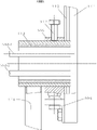
And the version of heat collector 1-1 described in the utility model, as shown in Figure 3.It has the glass tube with vacuum 1-1-2 by the collector metal medium tube 1-1-2-1 of the fixing structure that takes the shape of the letter U of metal fin, the medium of its thermal-arrest medium tube advances, outlet 1-1-2-1,1-1-2-2, all stretch outside glass tube with vacuum 1-1-2, the two ends of condenser 1-1-1, be inlaid in a Precision Aluminum foundry goods left side respectively, in the first embedding slot 1-1-3-1 of right microscope base 1-1-3, and be located at the both sides side cover plate 115 of condenser 1-1-1 both-side opening end, be inlaid in the second embedding slot 1-1-3-2 of microscope base 1-1-3, a left side, right microscope base 1-1-3 bottom is held and is connected respectively with about connector (three angle steel) 1-1-4, left and right sides base 1-1-5 holds and is connected respectively with about connector 1-1-4, the two ends of glass tube with vacuum 1-1-2, to be axis hole equipped with the axle sleeve of left and right sides support member 1-1-6 respectively, the axle sleeve of base 1-1-5 is sleeved on the axle sleeve of support member 1-1-6, and the axle sleeve of base 1-1-5 is provided with to adjust the screw 1-1-7 at condenser 1-1-1 inclination angle.
The specific constructive form of described heat collector 1-1 is asked for an interview the application documents of " the middle temperature solar heat collector " applied for by the applicant and the same applying date.
The utility model is located at the steam output pipe road 2-3 on the steam generator 2 casings top, by a plurality of output arms, respectively with cooking food (meal, steamed bun, dish) case, (bath water) device boils water, refrigeration air conditioner, heating device, the steam curer is connected with pipelines such as vapour with manufacturing industry processing medium bath and agricultural booth, to supply with required steam.
And several solar concentrating collectors 1-1 of described heat collector group 1 is the formation square formation to arrange, with effective saving floor space.
A kind of thermal-arrest medium input house steward 1-2 and thermal-arrest medium delivery trunk 1-3 of described heat collector 1 of exemplary embodiments all adopt Φ 150mm pipe, and described input pipe connects case 1-1-3 and efferent duct connects case 1-1-4, all adopts Φ 100mm pipe; And when adopt 2 the above connect case 1-1-3, during the 1-1-4 series connection, then adopt the 100mm cutting ferrule to connect;
And the slot opening of the slot light collection mirror 1-1-1 of its described heat collector 1-1 is 400mm, and flute length is 1700mm, and groove depth is 420mm, and heat collector 1-1 is the East and West direction layout, 8 of every rows, 40 heat collectors of totally 5 rows; The notch light-receiving area of each heat collector 1-1 is 0.68m
2, the notch light-receiving area of 40 heat collector 1-1 amounts to 27.2m
2
Experimental result shows that described exemplary embodiments is at the total irradiation 〉=800w/m of sunshine
2Situation under, the medium oil temperature that enters heat exchanger 2-1, generally about 110 ℃, the medium temperature of thermal-arrest medium heat exchanger exit is in 90 ~ 100 ℃ of scopes, vapor (steam) temperature is about 102 ℃, as sunlight irradiation amount>950w/m
2The time, vapor (steam) temperature can reach 〉=103 ℃, and the operate as normal time limit of the present utility model can reach 〉=and 25 years.
And in the high altitude localities (height above sea level in most of area in Tibet be 4000m or below the 4000m), its atmospheric pressure is 61.61kPa, available High Pressure Difference (0.05MPa) steam box, guarantee under local low air pressure condition, the steam box internal pressure is still reached and keep 0.11MPa, and can equally with common height above sea level condition implement prepared food things such as decatize rice.
Experimental result shows that the utility model has been obtained very significantly techno-economic effect.
Claims (7)
1. steam raising plant that adopts the CPC solar concentrating collector, it comprises: have CPC condenser (1-1-1) solar concentrating collector (1-1) spaced apart by several and arrange the heat collector group (1) who forms and the steam generator (2) with thermal-arrest medium heat exchanger; The thermal-arrest medium input mouth of pipe (1-1-2-1) of the collector metal pipe that is located at the structure that takes the shape of the letter U in the glass tube with vacuum of all CPC concentrating collectors (1-1) of described heat collector group (1) and the thermal-arrest medium output mouth of pipe (1-1-2-2) thereof are connected with thermal-arrest medium delivery trunk (1-3) pipeline with heat collector group's (1) thermal-arrest medium input house steward (1-2) respectively; By heat exchanger (2-1) water that is present in steam generator (2) casing is heated, and generate steam; In the thermal-arrest medium loop, be provided with energy storage case (3) and first liquid pump (4),
It is characterized in that:
A, the thermal-arrest medium input mouth of pipe (1-1-2-1) of described CPC concentrating collector (1-1) and the thermal-arrest medium output mouth of pipe (1-1-2-2) thereof, be to connect case (1-1-3) by input pipe respectively and efferent duct connects case (1-1-4), and be connected with thermal-arrest medium delivery trunk (1-3) pipeline with thermal-arrest medium input house steward (1-2) respectively;
B, described energy storage case (3) is provided with heater (6); Described energy storage case (3) is arranged in the rear of steam generator (2); Described heat collector group's (1) thermal-arrest medium delivery trunk (1-3) and thermal-arrest medium input house steward (1-2) thereof, import respectively in the energy storage case (3), and the outlet of thermal-arrest medium delivery trunk (1-3) is positioned at the top of energy storage case (3), thermal-arrest medium input house steward's (1-2) entrance, be positioned at the bottom of energy storage case (3), thereby constitute heat collector group's (1) the big loop of thermal-arrest medium; And the thermal-arrest medium input pipe (2-1-1) of the thermal-arrest medium heat exchanger of steam generator (2), and thermal-arrest medium efferent duct (2-1-2), introduce respectively in the energy storage case (3), and the entrance of thermal-arrest medium input pipe (2-1-1) is positioned at the top of energy storage case (3), the outlet of thermal-arrest medium efferent duct (2-1-2), be positioned at the bottom of energy storage case (3), thereby constitute the thermal-arrest medium minor loop of steam generator (2);
C also comprises second liquid pump (5); Described first liquid pump (4) is arranged on heat collector group's (1) thermal-arrest medium input house steward (1-2) pipeline of contiguous energy storage case (3), and second liquid pump (5) is arranged on thermal-arrest medium input pipe (2-1-1) pipeline of thermal-arrest medium heat exchanger of steam generator (2); Make thermal-arrest medium shuttling movement in big loop of heat collector group (1) by first liquid pump (4), and make thermal-arrest medium shuttling movement in minor loop of steam generator (2) by second liquid pump (5);
D, described thermal-arrest medium heat exchanger, be spiral coil heat exchanger (2-1), and its thermal-arrest medium input port (2-1-1-1) is in the centre of spiral coil, and its thermal-arrest medium delivery outlet (2-1-1-2), be in the outermost of spiral coil, and be connected with thermal-arrest medium efferent duct (2-1-2) pipeline with thermal-arrest medium input pipe (2-1-1) respectively, thereby constitute spiral coil shell-side boiling heat transfer; And described spiral coil heat exchanger (2-1) is 1 at least, when spiral coil heat exchanger (2-1) has when a plurality of, then a plurality of spiral coil heat exchangers (2-1) are evenly arranged in steam generator (2) casing, and are connected with thermal-arrest medium efferent duct (2-1-2) branch line with thermal-arrest medium input pipe (2-1-1) by pipe joint respectively;
E, the cpc slot light collection mirror (1-1-1) of described solar concentrating collector (1-1), arranged by bilateral symmetry, be connected and constitute the slot type surface mirror (111) of the structure that takes the shape of the letter U by involute section (1-1-1-1) and parabolic segment (1-1-1-2) transition, and substrate glass (112) is formed; Described surface mirror (111) is back surface mirror, and in the rear surface of surface mirror (111) glass-based (111-4), plating is furnished with reflexed light film (111-1) and protective film (111-2) successively from the inside to the outside; The rear surface of described surface mirror (111) is integral formation CPC slot light collection mirror (1-1-1) by adhesive layer (111-3) and substrate glass (112) compound sticking;
F, also comprise the notch end that is closely contacted on described slot light collection mirror (1-1-1) respectively and cover-plate glass (114) and the side glass cover-plate (115) of both-side opening end, by cover-plate glass (114) and both sides side glass cover-plates (115), the CPC slot light collection mirror of the feasible structure that takes the shape of the letter U is full closeding state.
2. the steam raising plant of employing CPC solar concentrating collector according to claim 1 is characterized in that: also comprise the automaton (5) with automatic controller; Described automaton (5), comprise: automatic controller (5-1), be located at first magnetic valve (5-2) of heat collector group's (1) thermal-arrest medium delivery trunk (1-3) downstream portion, be located at first temperature sensor (5-3) in the energy storage case (3), be located at second temperature sensor (5-4) in the steam generator (2), be located at second magnetic valve (5-5) on steam generator (2) and the city public water water source attaching pipeline, be located at the level sensor (5-6) in steam generator (2) casing, be located at the 3rd magnetic valve (5-7) on medium efferent duct (2-1-2) pipeline of thermal-arrest medium heat exchanger and be located at flow sensor (5-8) on the steam output pipe road (2-3) that steam generator (2) casing pushes up; Described first magnetic valve (5-2), first temperature sensor (5-3), second temperature sensor (5-4), second magnetic valve (5-5), level sensor (5-6), the 3rd magnetic valve (5-7), flow sensor (5-8), and first liquid pump (4) and second liquid pump (5), all be electrically connected with automatic controller (5-1) and accept automatic controller (5-1) control.
3. the steam raising plant of employing according to claim 1 CPC solar concentrating collector, it is characterized in that: the caliber of described spiral coil heat exchanger (2-1) is in 10 ~ 12mm scope, the spacing of adjacent 2 tube and tube is not less than 4mm, and its spiral number of turns is in 10 ~ 15 circle scopes.
4. the steam raising plant of employing according to claim 1 CPC solar concentrating collector, it is characterized in that: described reflexed light film (111-1) is silver-colored reflexed light film, described protective film (111-2) is the copper protective film.
5. the steam raising plant of employing according to claim 1 CPC solar concentrating collector, it is characterized in that: the outer surface of described notch cover-plate glass (114) and notch both sides side glass cover-plates (115) also all from the inside to the outside successively plating be furnished with sunshine high antireflection film layer and automatically cleaning rete, and both inner surface also all plating be furnished with sunshine high antireflection film layer.
6. the steam raising plant of employing CPC solar concentrating collector according to claim 1 is characterized in that: in the downstream portion of heat collector group (1) thermal-arrest medium delivery trunk (1-3) pipeline, also be provided with liquid-steam separator (7).
7. the steam raising plant of employing according to claim 1 CPC solar concentrating collector, it is characterized in that: the casing of described steam generator (2) is cylindric, and its diameter aspect ratio is in 2 ~ 2.5:1 scope.
Priority Applications (1)
| Application Number | Priority Date | Filing Date | Title |
|---|---|---|---|
| CN2013200613054U CN203147717U (en) | 2013-02-04 | 2013-02-04 | Steam generation device with CPC (Compound Parabolic Concentrator) solar concentrator collectors |
Applications Claiming Priority (1)
| Application Number | Priority Date | Filing Date | Title |
|---|---|---|---|
| CN2013200613054U CN203147717U (en) | 2013-02-04 | 2013-02-04 | Steam generation device with CPC (Compound Parabolic Concentrator) solar concentrator collectors |
Publications (1)
| Publication Number | Publication Date |
|---|---|
| CN203147717U true CN203147717U (en) | 2013-08-21 |
Family
ID=48975237
Family Applications (1)
| Application Number | Title | Priority Date | Filing Date |
|---|---|---|---|
| CN2013200613054U Withdrawn - After Issue CN203147717U (en) | 2013-02-04 | 2013-02-04 | Steam generation device with CPC (Compound Parabolic Concentrator) solar concentrator collectors |
Country Status (1)
| Country | Link |
|---|---|
| CN (1) | CN203147717U (en) |
Cited By (4)
| Publication number | Priority date | Publication date | Assignee | Title |
|---|---|---|---|---|
| CN103090347A (en) * | 2013-02-04 | 2013-05-08 | 常州龙腾太阳能热电设备有限公司 | Steam generating device adopting compound parabolic concentrator (CPC) solar collector |
| CN103759237A (en) * | 2014-02-10 | 2014-04-30 | 山东力诺瑞特新能源有限公司 | Medium-temperature solar steam system |
| CN105157255A (en) * | 2015-09-25 | 2015-12-16 | 常州龙腾太阳能热电设备有限公司 | Day-by-day tracking control system and method for Fresnel type reflector set devices |
| CN108167797A (en) * | 2018-02-08 | 2018-06-15 | 广州聚能太阳能科技有限公司 | A kind of straight-through type solar energy steam generating system |
-
2013
- 2013-02-04 CN CN2013200613054U patent/CN203147717U/en not_active Withdrawn - After Issue
Cited By (5)
| Publication number | Priority date | Publication date | Assignee | Title |
|---|---|---|---|---|
| CN103090347A (en) * | 2013-02-04 | 2013-05-08 | 常州龙腾太阳能热电设备有限公司 | Steam generating device adopting compound parabolic concentrator (CPC) solar collector |
| CN103090347B (en) * | 2013-02-04 | 2014-08-06 | 常州龙腾太阳能热电设备有限公司 | Steam generating device adopting compound parabolic concentrator (CPC) solar collector |
| CN103759237A (en) * | 2014-02-10 | 2014-04-30 | 山东力诺瑞特新能源有限公司 | Medium-temperature solar steam system |
| CN105157255A (en) * | 2015-09-25 | 2015-12-16 | 常州龙腾太阳能热电设备有限公司 | Day-by-day tracking control system and method for Fresnel type reflector set devices |
| CN108167797A (en) * | 2018-02-08 | 2018-06-15 | 广州聚能太阳能科技有限公司 | A kind of straight-through type solar energy steam generating system |
Similar Documents
| Publication | Publication Date | Title |
|---|---|---|
| CN203147717U (en) | Steam generation device with CPC (Compound Parabolic Concentrator) solar concentrator collectors | |
| CN203656882U (en) | Solar heat exchange continuous steam supply system | |
| CN2384176Y (en) | Heat pipe solar heat collector | |
| CN209445488U (en) | A kind of heating system based on CPC solar thermal collector | |
| CN201852307U (en) | Solar vacuum tube matrix heat collection system | |
| CN103090347B (en) | Steam generating device adopting compound parabolic concentrator (CPC) solar collector | |
| CN103032967B (en) | Efficient flat plate solar water heater without water tank | |
| CN204513775U (en) | A kind of dual-energy water heater with side dress water replanishing device | |
| CN210141607U (en) | Distributed solar valley electricity energy storage heat pump heating system | |
| CN201025411Y (en) | A novel solar heat collector | |
| CN203704384U (en) | Multi-row evacuated collector tube type solar thermal collector | |
| CN208205158U (en) | A kind of fused salt accumulation of heat heating system | |
| CN102788433B (en) | Solar thermal collector and water heater | |
| CN207569968U (en) | A kind of board-like water-electricity integrated radiator system | |
| CN201787743U (en) | Solar collector | |
| CN205619240U (en) | Solar energy steam oven | |
| CN101118095B (en) | Double-layer glass vacuum metal pipe type solar heat-collector | |
| CN104792037A (en) | Solar energy photovoltaic power generation and heat production double-energy plate and use method thereof | |
| CN207180054U (en) | Solar superconducting hot plate type water heater | |
| CN204757398U (en) | Thermal -arrest board, solar panel core, heat collector, water heater and utilize system | |
| CN208186860U (en) | Lustration type keeps the temperature energy storage heat-exchanging water tank | |
| CN201945049U (en) | Heat collecting system with double-row solar vacuum tube array | |
| CN210374128U (en) | Solar heat collection and energy storage device | |
| CN208595710U (en) | A kind of intelligent solar water heater | |
| CN208595712U (en) | A kind of energy-efficient solar water heater |
Legal Events
| Date | Code | Title | Description |
|---|---|---|---|
| C14 | Grant of patent or utility model | ||
| GR01 | Patent grant | ||
| AV01 | Patent right actively abandoned |
Granted publication date: 20130821 Effective date of abandoning: 20140806 |
|
| RGAV | Abandon patent right to avoid regrant |