CN203135515U - Portable solar router - Google Patents
Portable solar router Download PDFInfo
- Publication number
- CN203135515U CN203135515U CN201320130987.XU CN201320130987U CN203135515U CN 203135515 U CN203135515 U CN 203135515U CN 201320130987 U CN201320130987 U CN 201320130987U CN 203135515 U CN203135515 U CN 203135515U
- Authority
- CN
- China
- Prior art keywords
- router
- charging
- circuit
- output
- solar energy
- Prior art date
- Legal status (The legal status is an assumption and is not a legal conclusion. Google has not performed a legal analysis and makes no representation as to the accuracy of the status listed.)
- Expired - Lifetime
Links
Images


Landscapes
- Charge And Discharge Circuits For Batteries Or The Like (AREA)
Abstract
The utility model provides a portable solar router which comprises a battery which supplies power to a 3G router, a storage battery charging circuit, a CPU system, a 3G module and a WiFi module. The portable solar router also comprises a solar battery arranged at the outer surface of a 3G router shell. The storage battery charging circuit comprises a solar charging circuit which charges the storage battery by using the solar battery and a charging management circuit. A novel 3G router is designed in the utility model, and two charging modes which are a self solar charging mode and an external charging mode can be realized. The solar charging is carries out at any time and any place and is not influenced by indoor and outdoor light. Through the external charging, the fast charging of equipment can be realized in a charging place.
Description
Technical field
The utility model relates to the electric supply installation field of router, and particularly a kind of solar cell and civil power dual mode of adopting is the portable type solar energy router of charge in batteries.
Background technology
Portable router is a kind of WiFi equipment with the 3G function, it have lightly be easy to carry, functional characteristics such as flexible networking whenever and wherever possible, be the necessary article that the business people goes on business, travels.Portable set has a common characteristic, needs exactly to charge the battery.Because battery sizes is subjected to the restriction of equipment self volume, battery capacity all can not be accomplished very big.The 3G router that general battery capacity is 1500mA/h runs full-service can be with 4 hours, and stand-by time is no more than 10 hours.Generally all need a fixed place for equipment charge, and solar recharging does not just need to be subjected to this constraint.
Solar energy is inexhaustible, nexhaustible clean energy resource, and solar power generation is very welcome new technology at present.Solar cell has monocrystalline silicon battery, polycrystal silicon cell and amorphous silicon membrane battery at present.Monocrystalline silicon battery has the battery conversion efficiency height, good stability, but cost is higher; Amorphous silicon film solar battery then has the production efficiency height, and is with low cost, but conversion efficiency is lower, and efficient decays than very fast; Polysilicon solar cell then has the efficient of stable conversion, and the ratio of performance to price is the highest.It is only giving portable router charging with polysilicon solar cell.
Shortcoming with solar recharging is that the solar panel volume is very big, and energy output is subjected to the restriction of sunlight.Solar panel (or battery) is made up of the solar units of one or more series and parallels.A solar units produces the voltage of 0.7V, and this voltage is subjected to the influence of light intensity and irradiating angle.Portable router is subjected to volume restrictions, and the solar units area can not be big, so the charge efficiency of solar energy is vital.
Little owing to volume as router, its exterior surface area is limited, at present, if the outer surface of outer cover of whole router is all sticked solar panel, can not produce effective electric current for the employed storage battery of router (rechargeable battery) charging, therefore, also there is not to adopt the solar energy router that the charging of solar panel power supply storage battery is installed at the router cover outer surface at present.
The utility model content
The purpose of this utility model provides a kind of portable type solar energy router that the charging of solar panel power supply storage battery is installed at the router cover outer surface.
The technical solution of the utility model is: a kind of portable type solar energy router is included as storage battery, battery charging circuit that router is powered, cpu system, 3G module and WiFi module; Also comprise and comprise in the solar cell that is arranged on the router cover outer surface, the described battery charging circuit and utilize solar cell to be solar charging circuit and the charge management circuit of charge in batteries; Described solar charging circuit links to each other with described solar cell, comprise the small energy pick-up circuit of solar energy, the input of the small energy pick-up circuit of described solar energy links to each other with described solar cell, the direct voltage that output produces 5V links to each other with described charge management circuit, and described charge management circuit receives the 5V direct voltage and described storage battery is connected to charge in batteries.
Further, in the above-mentioned portable type solar energy router: the small energy pick-up circuit of described solar energy comprises that model is the boost converter of BQ25504;
The output of Vin_dc termination solar cell described boost converter) is provided with between the line of Vin_dc end and the output of solar cell and ground and imports battery C1;
Between Vin_dc end and ground, also be provided with divider resistance R1 and the divider resistance R2 of polyphone; Connect the Voc_samp end of boost converter between divider resistance R1 and the divider resistance R2; The Vref_samp of boost converter is by capacitor C 3 ground connection;
Be connected with the boost conversion inductance at the Vin_dc of boost converter end and Lbst end;
At the temporary lithium battery of the Vbat of boost converter termination;
Pass through output capacitance C2 ground connection at the 5V of boost converter output.
Further, in the above-mentioned portable type solar energy router: described charge management circuit comprises that model is the charging management chip of BQ24166, an input USB of described charging management chip connects the 5V output of the boost converter of the small energy pick-up circuit of described solar energy, its output SW meets buck inductor LB, buck inductor LB produces the output of 4.2V direct current by filter capacitor C4 ground connection;
Described 4.2V direct current output inserts in the charging management chip, connects the storage battery of powering into the 3G router from the output of BAT pin.
Further, in the above-mentioned portable type solar energy router: another input of described charging management chip IN connects the output of line charger.
Further, in the above-mentioned portable type solar energy router: described 4.2V direct current output produces 3.3V, 2.5V, 1V and 4.2V by the DC/DC transducer.
Further, in the above-mentioned portable type solar energy router: the SOC chip that described cpu system model is RTL8196D and connected DDR1, Flash.
Further, in the above-mentioned portable type solar energy router: described WiFi module comprises that model is the WiFi chip of RTL8188ER, built-in 2.4G WiFi antenna, and described WiFi chip is connected with cpu system by the PCIE interface.
Further, in the above-mentioned portable type solar energy router: described 3G module comprises that model is that the 3G chip of QSC6085 links to each other by usb bus with cpu system, and SIM card is by described 3G module controls, and the 3G antenna is built-in.
The utility model has designed a kind of new 3G router, and it can be realized from body solar recharging and two kinds of charging modes of external charging.Solar recharging is not subjected to influence indoor, outdoor light whenever and wherever possible; External charging can be realized the quick charge of equipment in the place that the charging place is arranged.
The solar charging circuit conversion efficiency is high by 80%, starts operating voltage and is low to moderate 310mW; After the startup work, picking up solar energy u watt level still can operate as normal.
The 3G router of the utility model design has Highgrade integration: solar recharging and 3G router are integrated in one veneer PCB is integrated solar charging circuit, 3G and WiFi circuit system.Volume has only hand size, accomplish light, be easy to carry.
Below in conjunction with specific embodiment the utility model is done comparatively detailed description.
Description of drawings
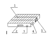
Fig. 1 is the utility model router complete machine schematic diagram.
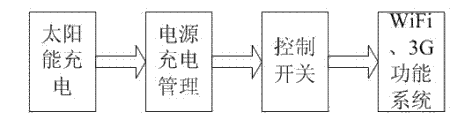
Fig. 2 is the utility model route system circuit function block diagram.
Fig. 3 is the small energy pick-up circuit schematic diagram of the utility model router solar energy.
Fig. 4 is the utility model router sun-generated electric power charge management circuit schematic diagram.
Fig. 5 is the utility model router main system circuit block diagram.
Embodiment
In the present embodiment:
Solar panel 1: carry out opto-electronic conversion, provide energy to system.
SIM card interface 2: the user inserts SIM card or UIM card, by 3G WCDMA, CDMA2000, the online of TD-SCDMA network high-speed.
RJ45 Ethernet interface 5: cable access network is provided, can be configured to WAN mouth or LAN mouth by software.
USB interface 4: power interface, connect a USB patchcord, can realize that notebook or power supply adaptor are to power devices.
Be the circuit system function diagram of present embodiment as shown in Figure 2, this circuit system is made up of three modules and control switch.Module 1 realizes solar recharging; Module 2 realizes the power management of external power source and solar recharging; Module 3 realizes WiFi and 3G systemic-function.
In the present embodiment, module 1 mainly is made of solar cell, boost charge circuit and store electrical energy element lithium battery.Designed solar battery panel size is 10cm*6cm, is formed by 4 battery cell series and parallel.Each battery cell produces the about 0.5V of direct voltage, electric current 20mA~25mA/cm2, and whole solar cell can provide the power energy of about 60mW.As shown in Figure 1.
Designed boost charge circuit has utmost point low quiescent current and surpasses 80% high conversion efficiency, and 330mV cold start-up voltage makes that charging circuit also can start work under low luminous intensity.Fig. 3 is solar recharging module main circuit.U1 is boost converter IC BQ25504.
Lbst is the boost conversion inductance, and C1, C2 are input, output capacitance.U1 BQ25504 has MPPT maximum power point tracking MPPT technology, optimizes the energy from solar energy collecting.By the ratio of resistance R 1, R2 is set, the best power collection point can be set.To solar cell, be 80% by the best point of experimental test, namely be reference voltage Vref is set is 80% of solar cell open circuit voltage Vocv.Capacitor C 3 has been the effects that keep Vref, and BQ25504 upgrades the sampling reference voltage Vref every 16s.
U1 BQ25504 Pin pin Vbat connects the energy-storage travelling wave tube lithium battery, and the lithium electromagnetism that this lithium electromagnetism is a kind of temporary energy is called temporary lithium electromagnetism, and pin Vstor output connects load.Connect by the FET pipe between them.By arranging, monitoring under-voltage and overpressure value, can realize protecting the overshoot of lithium battery and cross and put.Temporary lithium battery adopts the lighium polymer material, can accomplish arbitrary shape and reduce cost, and capacity is 600mAH.
The power source charges management circuit as shown in Figure 4, its purpose is the intelligent management of realizing from body solar recharging and two kinds of charging modes of external power source charging.When external power supply not, it is exactly solar recharging always.When external power supply, when the solar recharging energy storage continued, external power supply also can charge the battery, and can also directly power to system simultaneously.As shown in Figure 4, chip U2 BQ24166 has the binary channels input, connects solar energy module output and USB power supply respectively.The solar energy module output current is limited in the 100mA, and the USB source current is limited in the 1A.When U2 being set the dual input power supply being arranged at the same time, preferably with pin IN input.Lb is buck inductor, lithium ion battery output 4.2V voltage, and capacity is 1600mAH.
Power control switch is soft switch, and the circuit of being made up of two d type flip flops forms power control signal, realizes battery to the cut-out of system's power supply and opens control.
WiFi, 3G function system:
For making more power saving of system, integration of compactization more, system hardware selects for use the higher power supply IC of conversion efficiency, system-level SoC single-chip to finish.3G, WiFi function system main circuit framework are as shown in Figure 5.
Rechargeable battery is powered to system by control switch, and 4.2V becomes 3.3V, 2.5V and 1V through the DC/DC transducer; 4.2V directly gives the 3G module for power supply simultaneously.
SoC chip RTL8196D and Flash, DDR1 form a little cpu system, realize management, the control function of data.RTL8188ER is the WiFi chip, and it can realize the 11b/g/n speed of the highest 150Mbps; Be connected with CPU RTL8196D by the PCIE interface.2.4G the WiFi antenna is built-in.
The inner integrated 100,000,000 PHY functions of RTL8196D, external transformer, RJ45 can realize 10M/100M wire transmission speed.RTL8196D meets the EEE standard, has the Ethernet arousal function, and this makes it that lower power consumption be arranged.
The module interface of 3G module and RTL8196D is the PCIE interface, and actual cabling is usb bus.The 3G module of switching different systems can make it use in different 3G networks, and SIM card is by the 3G module controls.The 3G antenna also is built-in.
The utility model has designed a kind of new 3G router, and it has three innovative points:
It can be realized from body solar recharging and two kinds of charging modes of external charging.Solar recharging is not subjected to influence indoor, outdoor light whenever and wherever possible; External charging can be realized the quick charge of equipment in the place that the charging place is arranged.
The solar charging circuit conversion efficiency starts operating voltage and is low to moderate 310mW up to more than 80%; After the startup work, pick up solar voltage be low to moderate 80mV still can operate as normal.
Solar recharging and 3G router are integrated in one, integrated solar recharging, 3G, WiFi and wired ethernet function, volume has only hand size, also claims " pocket " solar energy 3G router.
Present embodiment has designed a kind of new portable 3G router, and it can be realized from body solar recharging and two kinds of charging modes of external charging.Solar recharging is not subjected to influence indoor, outdoor light whenever and wherever possible; External charging can be realized the quick charge of equipment in the place that the charging place is arranged.Designed solar charging circuit has high conversion efficiency and the startup ability to work under the low light level.The portable 3G router of design is integrated in one solar recharging and 3G router, integrated solar recharging, 3G, WiFi and wired ethernet function, and volume has only hand size, has created a kind of new product form.
Claims (8)
1. a portable type solar energy router is included as storage battery, battery charging circuit that router is powered, cpu system, 3G module and WiFi module; It is characterized in that: also comprise comprising in the solar cell that is arranged on the router cover outer surface, the described battery charging circuit and utilizing solar cell to be solar charging circuit and the charge management circuit of charge in batteries; Described solar charging circuit links to each other with described solar cell, comprise the small energy pick-up circuit of solar energy, the input of the small energy pick-up circuit of described solar energy links to each other with described solar cell, the direct voltage that output produces 5V links to each other with described charge management circuit, and described charge management circuit receives the 5V direct voltage and described storage battery is connected to charge in batteries.
2. portable type solar energy router according to claim 1, it is characterized in that: the small energy pick-up circuit of described solar energy comprises that model is the boost converter (U1) of BQ25504;
The output of the Vin_dc termination solar cell of described boost converter (U1) is provided with between the line of Vin_dc end and the output of solar cell and ground and imports battery C1;
Between Vin_dc end and ground, also be provided with divider resistance R1 and the divider resistance R2 of polyphone; Connect the Voc_samp end of boost converter (U1) between divider resistance R1 and the divider resistance R2; The Vref_samp of boost converter (U1) is by capacitor C 3 ground connection;
Be connected with the boost conversion inductance at the Vin_dc of boost converter (U1) end and Lbst end;
At the temporary lithium battery of the Vbat termination of boost converter (U1);
5V output at boost converter (U1) passes through output capacitance C2 ground connection.
3. portable type solar energy router according to claim 1, it is characterized in that: described charge management circuit comprises that model is the charging management chip (U2) of BQ24166, an input USB of described charging management chip (U2) connects the 5V output of the boost converter (U1) of the small energy pick-up circuit of described solar energy, its output SW meets buck inductor LB, buck inductor LB produces the output of 4.2V direct current by filter capacitor C4 ground connection;
Described 4.2V direct current output inserts in the charging management chip (U2), connects the storage battery of powering into the 3G router from the output of BAT pin.
4. portable type solar energy router according to claim 3, it is characterized in that: another input of described charging management chip (U2) IN connects the output of line charger.
5. portable type solar energy router according to claim 3 is characterized in that: described 4.2V direct current output produces 3.3V, 2.5V, 1V and 4.2V by the DC/DC transducer.
6. according to arbitrary described portable type solar energy router in the claim 1 to 5, it is characterized in that: the SOC chip that described cpu system model is RTL8196D and connected DDR1, Flash.
7. portable type solar energy router according to claim 6, it is characterized in that: described WiFi module comprises that model is the WiFi chip of RTL8188ER, built-in 2.4G WiFi antenna, described WiFi chip is connected with cpu system by the PCIE interface.
8. portable type solar energy router according to claim 6 is characterized in that: described 3G module comprises that model is that the 3G chip of QSC6085 links to each other by usb bus with cpu system, and SIM card is by described 3G module controls, and the 3G antenna is built-in.
Priority Applications (1)
| Application Number | Priority Date | Filing Date | Title |
|---|---|---|---|
| CN201320130987.XU CN203135515U (en) | 2013-03-21 | 2013-03-21 | Portable solar router |
Applications Claiming Priority (1)
| Application Number | Priority Date | Filing Date | Title |
|---|---|---|---|
| CN201320130987.XU CN203135515U (en) | 2013-03-21 | 2013-03-21 | Portable solar router |
Publications (1)
| Publication Number | Publication Date |
|---|---|
| CN203135515U true CN203135515U (en) | 2013-08-14 |
Family
ID=48943455
Family Applications (1)
| Application Number | Title | Priority Date | Filing Date |
|---|---|---|---|
| CN201320130987.XU Expired - Lifetime CN203135515U (en) | 2013-03-21 | 2013-03-21 | Portable solar router |
Country Status (1)
| Country | Link |
|---|---|
| CN (1) | CN203135515U (en) |
Cited By (3)
| Publication number | Priority date | Publication date | Assignee | Title |
|---|---|---|---|---|
| CN103138352A (en) * | 2013-03-21 | 2013-06-05 | 深圳市共进电子股份有限公司 | Portable solar router |
| CN107180886A (en) * | 2017-03-29 | 2017-09-19 | 深圳市富友昌科技股份有限公司 | Photovoltaic power generation apparatus and wearing electronic equipment |
| US10680456B2 (en) | 2015-08-24 | 2020-06-09 | Huawei Technologies Co., Ltd. | Wearable device and wearable device charging method |
-
2013
- 2013-03-21 CN CN201320130987.XU patent/CN203135515U/en not_active Expired - Lifetime
Cited By (4)
| Publication number | Priority date | Publication date | Assignee | Title |
|---|---|---|---|---|
| CN103138352A (en) * | 2013-03-21 | 2013-06-05 | 深圳市共进电子股份有限公司 | Portable solar router |
| CN103138352B (en) * | 2013-03-21 | 2015-01-07 | 深圳市共进电子股份有限公司 | Portable solar router |
| US10680456B2 (en) | 2015-08-24 | 2020-06-09 | Huawei Technologies Co., Ltd. | Wearable device and wearable device charging method |
| CN107180886A (en) * | 2017-03-29 | 2017-09-19 | 深圳市富友昌科技股份有限公司 | Photovoltaic power generation apparatus and wearing electronic equipment |
Similar Documents
| Publication | Publication Date | Title |
|---|---|---|
| CN103138352B (en) | Portable solar router | |
| CN106253434A (en) | A kind of micro power source catcher of internet of things oriented node | |
| CN102723752B (en) | Piezoelectric charging formula mobile terminal | |
| CN101552476A (en) | Household portable solar photovoltaic power | |
| CN201075719Y (en) | Solar energy mobile power supply device | |
| CN103227483A (en) | Solar charger capable of charging various batteries | |
| CN204835612U (en) | Take portable power source of remote monitoring | |
| CN203135515U (en) | Portable solar router | |
| CN101964605A (en) | Solar energy field emergency power supply | |
| CN205319785U (en) | Charging device is folded to solar energy | |
| CN202333932U (en) | ZIGBEE based energy-saving intelligent wireless charging device | |
| CN203722280U (en) | Solar USB charging device | |
| CN201075722Y (en) | Multi-functional solar energy charger circuit | |
| CN105634106A (en) | Solar folding charging device | |
| CN203339721U (en) | Solar energy charger | |
| CN202713736U (en) | Solar-powered LED energy-saving lighting device | |
| CN202680967U (en) | Solar-energy rechargeable back bag | |
| CN201504107U (en) | Portable household solar photovoltaic power supply | |
| CN201640863U (en) | Solar pack | |
| CN201813324U (en) | Portable intelligent solar energy power source | |
| CN104485716A (en) | Solar electrical bicycle charging device additionally installed on parking shed | |
| CN204928247U (en) | Charging system is switched to solar energy intelligence | |
| CN210183084U (en) | Portable solar charger | |
| CN204304538U (en) | A kind of solar electric vehicle charging device being installed at carport | |
| CN204517484U (en) | Mobile power supply device |
Legal Events
| Date | Code | Title | Description |
|---|---|---|---|
| C14 | Grant of patent or utility model | ||
| GR01 | Patent grant | ||
| CX01 | Expiry of patent term | ||
| CX01 | Expiry of patent term |
Granted publication date: 20130814 |