A kind of automatically controlled and lock body are easy to the electronic intelligence door lock of clutch
Technical field
The utility model belongs to the electronic lock field, especially to a kind of technological improvement of electronic intelligence door lock.
Background technology
Along with the technical development of electronic lock, now the technical of electronic anti-theft intelligent door lock done very ripely, the antitheft intelligent door lock of penetration of electron more and more in fields such as household, villa buildings.Chinese patent " fingerprint gate lock ", the patent No. are CN201110029557.4, this disclosure of the Invention a kind of fingerprint gate lock.Fingerprint gate lock comprises that the microprocessor unit that is arranged in the door lock shell, the finger scan module of scanning user fingerprints, the password input block that is provided for the password input and storage are about the memory cell of finger scan module and password input block information.Fingerprint gate lock also comprises the module-driving-electric machine controller that receives the driving signal from microprocessor unit.When the input block that accesses to your password is imported password or pressed particular key, by the driving force of the operated CD-ROM drive motor of the unlatching control signal of module-driving-electric machine controller, make the finger scan module from door lock, expose.Therefore, two step verification process must success just be opened door.Thereby the safety of door lock can improve.And Chinese patent " fingerprint gate lock ", the patent No. is CN200320107916.4, and a kind of fingerprint gate lock is provided, and comprises fingerprint detection element, DSP digital processing unit, dead bolt, driver blade, shifting block, outer handle, micromachine, worm and worm wheel.It also comprises driving lever, eccentric clutch block and outer handle axle sleeve.On the eccentric clutch block one group of mouth is arranged, its front end inserts dialling in the mouth on the eccentric clutch block, the rear portion of driving lever and the center of worm gear fix, on the outer handle axle sleeve notch is arranged, when eccentric clutch block turns over an angle, in its one jiao of notch that snaps on the outer handle axle sleeve, shifting block is meshed together with outer handle axle sleeve.Because adopted dynamo-electric conversion clutch to control between outer handle and shifting block, the movement of dead bolt is still manually finished by the door opener, thereby required electrokinetic moment greatly reduces.But these electronic anti-theft intelligent door locks are changed or keep in repair pretty troublesome if fault or electric-controlled parts, clutch component damage.One is pulled down difficult, and its two damages electric-controlled parts, clutch component will be sent the on-the-spot replacing of professional and technical personnel.The damage of some electric-controlled parts, clutch component will be returned repair in shop reason, pull down electric-controlled parts, clutch component after mechanical part just can't continue use.
Summary of the invention
The purpose of this utility model is for overcoming above shortcoming, provide a kind of simple in structure, make easily, electric-controlled parts, clutch component be easy to the electronic intelligence door lock that dismounting automatically controlled and lock body combination, that be convenient to after-sales service is easy to clutch.
The purpose of this utility model realizes by following scheme:
A kind of automatically controlled and lock body are easy to the electronic intelligence door lock of clutch, contain front panel, back shroud, rear board, front panel and rear board, back shroud are fixed on the both sides of lock core and door, and its structural feature is: electronic building brick and clutch component are separately fixed at the both sides of front panel, back shroud; Electronic building brick is electrically connected with clutch component.
Above-mentioned electronic building brick is provided with electronic building brick fixed bolt and electronic building brick reference column, plate is provided with the electronic building brick locating hole in front, electronic building brick is by the location of electronic building brick reference column and electronic building brick locating hole, and screw D, electronic building brick fixed bolt are fixed together.
Above-mentioned electronic building brick is provided with electronic building brick fixed bolt and electronic building brick card article, plate is provided with the electronic building brick draw-in groove in front, electronic building brick is by the location of electronic building brick card article and electronic building brick draw-in groove, and screw D, electronic building brick fixed bolt are fixed together.
Be respectively arranged with clutch component reference column and clutch component locating hole on above-mentioned clutch component, the rear board, clutch component is by the location of clutch component reference column and clutch component locating hole, and screw B, clutch component screw hole are fixed on the back shroud.
Above-mentioned clutch component is provided with the clutch component card article, back shroud is provided with clutch component screw hole and clutch component draw-in groove, clutch component is by the location of clutch component card article and clutch component draw-in groove, and screw B, clutch component screw hole are fixed on the back shroud.
Above-mentioned electronic building brick is electrically connected by the 10P connecting line with clutch component.
The beneficial effects of the utility model are:
1, the utility model simple in structure, be easy to make.
2, electronic building brick and clutch component are fixing simple, and dismounting is easy, and operation is very easy.
3, the user changes electronic building brick and clutch component is simply easy, if electronic building brick or clutch component fault or damage, as long as by screw D16 and screw B13 electronic building brick 24, clutch component 14 are unloaded, damaged part is returned factory's maintenance, and the mechanical lock part after the dismounting, load onto standby electronic building brick 24, clutch component 14 or die sleeve, do not influence and continue to use.Reduce the maintenance trouble, reduced the maintenance cost of producer widely.Also bring great convenience for the user.
Description of drawings
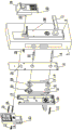
Fig. 1 is structural representation of the present utility model.
Fig. 2 is the structural representation of embodiment 2.
Structural representation when Fig. 3 clutch component is closed (state of closing the door).
Structural representation when Fig. 4 opens (door opening state) for clutch component.
Below in conjunction with embodiment, the utility model is described further.
The specific embodiment
Embodiment 1
As shown in Figure 1, a kind of automatically controlled and lock body are easy to the electronic intelligence door lock of clutch, contain front panel 2, back shroud 5, rear board 10, front panel 2 and rear board 10, back shroud 5 are fixed on the both sides of lock core and door, electronic building brick 24 is fixed on the back shroud 5 by two screw D16 and electronic building brick fixed bolt 23, and clutch component 14 is fixed on the back shroud 5 by two screw B and clutch component screw hole 20.
Embodiment 2
As shown in Figure 1, a kind of automatically controlled and lock body are easy to the electronic intelligence door lock of clutch, contain front panel 2, back shroud 5, rear board 10, and front panel 2 and rear board 10, back shroud 5 are fixed on the both sides of lock core and door.Electronic building brick 24 is provided with electronic building brick fixed bolt 23 and electronic building brick reference column 25, plate 2 is provided with electronic building brick locating hole 26 in front, electronic building brick 24 is by the location of electronic building brick reference column 25 with electronic building brick locating hole 26, and screw D16, electronic building brick fixed bolt 23 are fixed together; Be respectively arranged with two clutch component reference columns 12 and clutch component locating hole 17 at clutch component 14, rear board 10, clutch component 14 is by the location of clutch component reference column 12 and clutch component locating hole 17, and screw B13 is fixed on the back shroud 5.
Embodiment 3
As shown in Figure 2, a kind of automatically controlled and lock body are easy to the electronic intelligence door lock of clutch, contain front panel 2, back shroud 5, rear board 10, and front panel 2 and rear board 10, back shroud 5 are fixed on the both sides of lock core and door.Electronic building brick 24 is provided with electronic building brick fixed bolt 23 and electronic building brick card article 29, plate 2 is provided with electronic building brick draw-in groove 30 in front, electronic building brick 24 is by the location of electronic building brick card article 29 with electronic building brick draw-in groove 30, and screw D16, electronic building brick fixed bolt 23 are fixed together.Clutch component 14 is provided with clutch component card article 27, back shroud 5 is provided with clutch component screw hole 20 and clutch component draw-in groove 28, clutch component 14 is by the location of clutch component card article 27 and clutch component draw-in groove 28, and screw B13, clutch component screw hole 20 are fixed on the back shroud 5.
Operating principle:
With reference to Fig. 1, this enforcement electronic intelligent lock product is encrypting fingerprint sign indicating number series, 10P connecting line 22 is connected on the position of electronic building brick 24 correspondences, locate whole electronic building brick 24 in front above the plate 2 by electronic building brick reference column 25, electronic building brick locating hole 26, again by screw D16, from the back side of door, be screwed to electronic building brick fixed bolt 23 the insides, fastening electronic building brick 24 is in front on plate 2 and the back shroud 5; 10P connecting line 22 is connected on the correspondence position of clutch component 14, locate whole clutch component 14 in the back above the plate 10 by clutch component reference column 12, clutch component locating hole 17, tighten to clutch component screw hole 20 the insides by screw B13 again, clutch component 14 is fastened on the back shroud 5; When the automatically controlled part of door lock is not worked under the normal condition, when depressing the handle of preceding handle 1, handle idle running before this moment, door 3 can't be opened, when the finger that will configure fingerprint by on the fingerprint capturer of electronic building brick 24 or in the correct door-opening password of password key input, after chip is handled in the electronic building brick 24, pass to clutch component 14, the handle of handle 1 before depressing this moment, handle 1 rotates around its axis and drives square shaft A4 rotation, square opening before square shaft A4 passes above the handle driving member 7, handle driving member 7 rotates around its axis before driving, and by fixed thereon drive link A6, gives driven member 19 with the power transmission again, driven member 19 rotates around himself axis under action of centrifugal force, make driven member 19 with main dragging element 18 combine because of the work of clutch component 14 this moment, thereby main dragging element 18 is also rotated around its axis, square opening above the main dragging element 18 drives square shaft 2 21 and rotates, and drives lock body again and makes door to open.Screw A11 is fixed on rear board 10 on the back shroud 5; Rotate the back handle in doors, drive square shaft 2 21 and open the door within doors by back handle driving member 8, drive link B9.
With reference to Fig. 2,10P connecting line 22 is connected on the position of electronic building brick 24 correspondences, locate whole electronic building brick 24 in front above the plate 2 by electronic building brick card article 29, electronic building brick draw-in groove 30, again by screw D16, the back side from door, be screwed to electronic building brick fixed bolt 23 the insides, fastening electronic building brick 24 is in front on the plate 2; 10P connecting line 22 is connected on the correspondence position of clutch component 14, locate whole clutch component 14 in the back above the plate 10 by clutch component card article 27, back shroud draw-in groove 28, tighten to clutch component screw hole 20 the insides by screw B13 again, clutch component 14 is fastened on the back shroud 5;
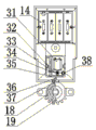
With reference to Fig. 3, Fig. 4, when door lock receives when correctly opening the door fingerprint or password, after electronic building brick 24 processing, can give 31 1 positive signal voltages of motor, motor 31 positive directions are rotated, the screw rod 33 that is fixed on above 31 in the motor also and then just changes, drive 32 of springs on screw rod 33, characteristic because of screw thread, can drive and drive spring 32 around driving locating shaft 38 swings, the straight end of driving spring 32 passes the driving square opening 34 above the T shape part 35, thereby driving T shape part 35 moves up and down, when motor 31 is just changeing, T shape part 35 down moves, on-of pin 36 is depressed simultaneously, on-of pin return spring 37 is compressed, drive main dragging element 18 when driven member 19 rotates at this moment and rotate, namely can open the door, after the success of opening the door, electronic building brick 24 provides a negative signal voltage to motor 31 again, reverse rotation when motor 31 is received the cathode voltage signal drives T shape part again and up moves, and on-of pin 36 can be subjected to 37 1 thrusts up of on-of pin return spring, force on-of pin 36 up to move, when driven member 19 rotated at this moment, main dragging element 18 can't rotate, thereby reaches the purpose of closing the door.