CN203112404U - Portable assembled and vertical type tripod - Google Patents
Portable assembled and vertical type tripod Download PDFInfo
- Publication number
- CN203112404U CN203112404U CN 201320134378 CN201320134378U CN203112404U CN 203112404 U CN203112404 U CN 203112404U CN 201320134378 CN201320134378 CN 201320134378 CN 201320134378 U CN201320134378 U CN 201320134378U CN 203112404 U CN203112404 U CN 203112404U
- Authority
- CN
- China
- Prior art keywords
- supporting leg
- crossbeam
- angle
- benchmark
- supporting legs
- Prior art date
- Legal status (The legal status is an assumption and is not a legal conclusion. Google has not performed a legal analysis and makes no representation as to the accuracy of the status listed.)
- Expired - Lifetime
Links
Images

Landscapes
- Casings For Electric Apparatus (AREA)
Abstract
A portable assembled and vertical type tripod comprises three supporting legs and is characterized in that the supporting legs respectively comprise a standard supporting leg and two stretching supporting legs, wherein a transverse beam is arranged at the top end of the standard supporting leg, an included angle between the transverse beam and the standard supporting leg is 90 degrees, sleeves are arranged at top ends of the stretching supporting legs respectively, included angles between the sleeves and the stretching supporting legs are 15 degrees to 45 degrees, and a hanging ring is arranged in the middle of the transverse beam. The portable assembled and vertical type tripod is simple in structure, low in precision requirement, low in manufacturing difficulty, and low in manufacturing cost. In addition, the standard supporting leg and the stretching supporting legs are connected through the sleeves and the transverse beam, disassembling and installation can be achieved, and convenience is brought to transportation and installation.
Description
Technical field
The utility model relates to the electric operating instrument, particularly a kind of portable group of vertical tripod.
Background technology
Along with the electric network reconstruction amount increases, the rural power grids upgrading, instead arrange, flood control and overhaul engineering quantity is many, the electric operating task is heavy.And owing to each electric power facility position dispersion of rural power grids, away from the city, the equipment that quality such as high-low pressure electric pole, distribution transformer are bigger needs to be transported to engineering site from the warehouse and installs.When this kind equipment of loading, unloading, need use tripod to lift equipment as support so that entrucking, unload.
Existing tripod comprises three legs, is provided with attaching parts on the leg top, is provided with the drag-line for constraint leg opening angle in the leg bottom, is provided with hook in the attaching parts bottom.During use, leg opens to three directions respectively, opens the back and uses the drag-line location.After lifting is finished, the leg withdrawal is got final product.
The attaching parts of the tripod of this structure, the action that needs realization to open, regain to three directions, the accuracy requirement height, and need bear equipment pressure, and desirable strength is big, and therefore, its manufacture difficulty is big, the cost height.In addition, the tall and big heaviness of this tripod, and can't dismantling needs integral transportation, and carrying, installation difficulty are big.
Summary of the invention
The technical problems to be solved in the utility model provide a kind of simple in structure, cost is low, dismantled and assembled, be convenient to portable group of vertical tripod carrying and install.
The utility model is achieved in that
A kind of portable group of vertical tripod, comprise three supporting legs, its special character is: described supporting leg is respectively a benchmark supporting leg and two extension supporting legs, be provided with crossbeam on benchmark supporting leg top, angle between described crossbeam and the benchmark supporting leg is 90 °, be provided with sleeve respectively on extension supporting leg top, described sleeve is 15 °~45 ° with the angle of upholding supporting leg, is provided with link at the crossbeam middle part.
Be respectively equipped with anti-heavy iron plate at the benchmark supporting leg with upholding the supporting leg bottom surface, be connected with a plurality of non-slip feet nails in anti-heavy iron plate bottom surface.
Described sleeve is 30 ° with the angle of upholding supporting leg, to guarantee the stability of tripod.
Described anti-heavy iron plate and the angle of upholding supporting leg, anti-heavy iron plate and benchmark supporting leg equal the angle between sleeve and the extension supporting leg, to reach optimum anti-settling effect.
The point of connection of described benchmark supporting leg and crossbeam is positioned at the crossbeam middle part, to guarantee balance.
Described link and crossbeam are affixed, and the angle between link and the benchmark supporting leg is 34 °~36 °, to guarantee the Joint strenght of link.
Described link and crossbeam loose joint.
The beneficial effects of the utility model are:
Simple in structure, accuracy requirement is low, and manufacture difficulty is little, low cost of manufacture.And the benchmark supporting leg is connected with crossbeam by sleeve with upholding between the supporting leg, can realize dismounting, is convenient to carrying and installation.
Description of drawings
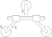
Fig. 1 is structural representation of the present utility model;
Fig. 2 is the birds-eye view of Fig. 1.
Among the figure: non-slip feet nail 1, anti-heavy iron plate 2, benchmark supporting leg 3 is upheld supporting leg 4, sleeve 5, crossbeam 6, link 7.
The specific embodiment
As shown in the figure, this portable group of vertical tripod comprises three supporting legs, and described supporting leg is respectively a benchmark supporting leg 3 and two extension supporting legs 4.Be provided with crossbeam 6 on benchmark supporting leg 3 tops, described benchmark supporting leg 3 is positioned at crossbeam 6 middle parts with the point of connection of crossbeam 6, and the angle between described crossbeam 6 and the benchmark supporting leg 3 is 90 °.Be provided with sleeve 5 respectively on extension supporting leg 4 tops, described sleeve 5 is 15 °~45 ° with the angle of upholding supporting leg 4, and in the present embodiment, described sleeve 5 is 30 ° with the angle of extension supporting leg 4.Be provided with link 7 at crossbeam 6 middle parts, described link 7 and crossbeam 6 affixed (but also loose joint), the angle between link 7 and the benchmark supporting leg 3 is 34 °~36 °, in the present embodiment, is example with 35 °.Be respectively equipped with anti-heavy iron plate 2 in benchmark supporting leg 3 and extension supporting leg 4 bottom surfaces, be connected with a plurality of non-slip feet nails 1 in anti-heavy iron plate 2 bottom surfaces, described anti-heavy iron plate 2 and the angle of upholding supporting leg 4, anti-heavy iron plate 2 and benchmark supporting leg 3 equal the angle between sleeve 5 and the extension supporting leg 4, to reach optimum anti-settling effect.
During use, will uphold supporting leg 4 and reverse, with benchmark supporting leg 3 common formation spiders.
Claims (7)
1. portable group of vertical tripod, comprise three supporting legs, it is characterized in that: described supporting leg is respectively a benchmark supporting leg and two extension supporting legs, be provided with crossbeam on benchmark supporting leg top, angle between described crossbeam and the benchmark supporting leg is 90 °, be provided with sleeve respectively on extension supporting leg top, described sleeve is 15 °~45 ° with the angle of upholding supporting leg, is provided with link at the crossbeam middle part.
2. portable group of vertical tripod according to claim 1 is characterized in that: be respectively equipped with anti-heavy iron plate at the benchmark supporting leg with upholding the supporting leg bottom surface, be connected with a plurality of non-slip feet nails in anti-heavy iron plate bottom surface.
3. portable group of vertical tripod according to claim 1 is characterized in that: described sleeve is 30 ° with the angle of upholding supporting leg.
4. portable group of vertical tripod according to claim 1 and 2 is characterized in that: described anti-heavy iron plate and the angle of upholding supporting leg, anti-heavy iron plate and benchmark supporting leg equal the angle between sleeve and the extension supporting leg.
5. portable group of vertical tripod according to claim 1 is characterized in that: the point of connection of described benchmark supporting leg and crossbeam is positioned at the crossbeam middle part.
6. portable group of vertical tripod according to claim 1, it is characterized in that: described link and crossbeam are affixed, and the angle between link and the benchmark supporting leg is 34 °~36 °.
7. portable group of vertical tripod according to claim 1 is characterized in that: described link and crossbeam loose joint.
Priority Applications (1)
| Application Number | Priority Date | Filing Date | Title |
|---|---|---|---|
| CN 201320134378 CN203112404U (en) | 2013-03-23 | 2013-03-23 | Portable assembled and vertical type tripod |
Applications Claiming Priority (1)
| Application Number | Priority Date | Filing Date | Title |
|---|---|---|---|
| CN 201320134378 CN203112404U (en) | 2013-03-23 | 2013-03-23 | Portable assembled and vertical type tripod |
Publications (1)
| Publication Number | Publication Date |
|---|---|
| CN203112404U true CN203112404U (en) | 2013-08-07 |
Family
ID=48892773
Family Applications (1)
| Application Number | Title | Priority Date | Filing Date |
|---|---|---|---|
| CN 201320134378 Expired - Lifetime CN203112404U (en) | 2013-03-23 | 2013-03-23 | Portable assembled and vertical type tripod |
Country Status (1)
| Country | Link |
|---|---|
| CN (1) | CN203112404U (en) |
Cited By (2)
| Publication number | Priority date | Publication date | Assignee | Title |
|---|---|---|---|---|
| CN103204444A (en) * | 2013-03-23 | 2013-07-17 | 国家电网公司 | Portable stand tripod |
| CN104567797A (en) * | 2015-01-15 | 2015-04-29 | 孟书芳 | Range finder support |
-
2013
- 2013-03-23 CN CN 201320134378 patent/CN203112404U/en not_active Expired - Lifetime
Cited By (2)
| Publication number | Priority date | Publication date | Assignee | Title |
|---|---|---|---|---|
| CN103204444A (en) * | 2013-03-23 | 2013-07-17 | 国家电网公司 | Portable stand tripod |
| CN104567797A (en) * | 2015-01-15 | 2015-04-29 | 孟书芳 | Range finder support |
Similar Documents
| Publication | Publication Date | Title |
|---|---|---|
| WO2013012761A3 (en) | Enhanced stability crane and methods of use | |
| CN203112404U (en) | Portable assembled and vertical type tripod | |
| CN202831637U (en) | Support frame for manufacturing steel girder | |
| CN202055547U (en) | Steel structure supporting system with adjustable inclined strut | |
| CN205046920U (en) | Steel pipe lattice formula framework lightning rod | |
| CN201512983U (en) | Double-triangle rod standing device | |
| CN103204444A (en) | Portable stand tripod | |
| CN203867265U (en) | Special hold hoop for connecting terminal pole electric pole and jacking rod | |
| CN203112392U (en) | Deformation-resistant climbing frame of tower crane | |
| CN205148143U (en) | Modularization crew cut tower crane jib loading boom shaping frock | |
| CN204963997U (en) | Foldable platform scale | |
| CN205089028U (en) | Weight type four -column communication base station tower | |
| CN201198659Y (en) | Formwork support system of prilling tower hanging structure | |
| CN202609835U (en) | Counterweight device for crane | |
| CN203998724U (en) | A kind of tower machine attached wall assembling and disassembling stand | |
| CN202754692U (en) | Lifting device for base-ring manufacturing for wind power generation | |
| CN208473425U (en) | Anti-reversing device and electric pole | |
| CN202322014U (en) | Girder and supporting leg connection structure of portal crane | |
| CN204737589U (en) | A hoist that is used for large -scale tower upright to hoist | |
| CN204920423U (en) | Shaft tower supports mound | |
| CN205998902U (en) | A kind of combination type stock section being applied to large-scale tower crane fast assembling-disassembling | |
| CN205558447U (en) | Found pole appurtenance | |
| CN204258086U (en) | A kind of power distribution cabinet assembly being easy to locate based on fan-shaped and annular splice plate | |
| CN203729653U (en) | Wind-resistant reinforced type iron tower | |
| CN203865897U (en) | Tower crane and transition joint thereof |
Legal Events
| Date | Code | Title | Description |
|---|---|---|---|
| C14 | Grant of patent or utility model | ||
| GR01 | Patent grant | ||
| CX01 | Expiry of patent term |
Granted publication date: 20130807 |
|
| CX01 | Expiry of patent term |