CN203112068U - Feeding mechanism of pipe clamp rubber assembly machine - Google Patents
Feeding mechanism of pipe clamp rubber assembly machine Download PDFInfo
- Publication number
- CN203112068U CN203112068U CN 201320095399 CN201320095399U CN203112068U CN 203112068 U CN203112068 U CN 203112068U CN 201320095399 CN201320095399 CN 201320095399 CN 201320095399 U CN201320095399 U CN 201320095399U CN 203112068 U CN203112068 U CN 203112068U
- Authority
- CN
- China
- Prior art keywords
- feeding
- pipe clamp
- roller
- material bearing
- assembly machine
- Prior art date
- Legal status (The legal status is an assumption and is not a legal conclusion. Google has not performed a legal analysis and makes no representation as to the accuracy of the status listed.)
- Expired - Fee Related
Links
Images


Abstract
The utility model discloses a feeding mechanism of a pipe clamp rubber assembly machine. The feeding mechanism of the pipe clamp rubber assembly machine comprises a feeding frame body. The upper end surface of the feeding frame body is provided with a front feeding roller and a rear feeding roller; feeding belts are placed on the front feeding roller and the rear feeding roller in a tensioning mode; hollow portions matched with pipe clamps are placed in the middles of the feeding belts; the front feeding roller or the rear feeding roller is connected with a feeding stepping motor; feeding rails are placed on the direct backs of the feeding belts; the feeding rails are parallel to the feeding belts, and are located below the upper end surface of the feeding frame body; feeding sliding blocks are placed on the feeding rails; feeding cylinders are placed before the feeding sliding blocks; piston rods of the feeding cylinders are connected with the feeding sliding blocks; vertical lifting cylinders are placed on the feeding sliding blocks; piston rods of the lifting cylinders are connected with a material bearing frame; the opening of the material bearing frame is upward U-shaped and is matched with the pipe clamps; and a material shifting mechanical arm used for shifting the pipe clamps at the tail ends of the feeding belts to the material bearing frame. The feeding mechanism of the pipe clamp rubber assembly machine is simple in structure and movement operation and not easy to break down.
Description
Technical field
The utility model relates to a kind of automatic pipe clamp rubber assembly machine.
Background technology
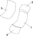
As shown in Figure 1, pipe clamp is made up of the hangers 2 at a curved portions 1 and curved portions 1 two ends, also is enclosed with a slice sheet rubber 3 on the curved portions 1 of pipe clamp.When pipe clamp and sheet rubber assemble, adopt pipe clamp rubber assembly machine to assemble, pipe clamp rubber assembly machine has the feed mechanism that pipe clamp is moved forward.Therefore the feed mechanism complex structure of existing pipe clamp rubber assembly machine, action complexity easily produce fault.
Summary of the invention
Above-mentioned for the feed mechanism that overcomes existing pipe clamp rubber assembly machine, the utility model provide a kind of feed mechanism of simple in structure, the pipe clamp rubber assembly machine that is difficult for producing fault.
The technical scheme in the invention for solving the technical problem is: a kind of feed mechanism of pipe clamp rubber assembly machine, comprise the feeding support body, feeding roller and back feeding roller before the upper surface of described feeding support body is provided with, tensioning has feeding belt on described preceding feeding roller and the back feeding roller, the central authorities of described feeding belt are provided with the hollow-out parts adaptive with pipe clamp, and described preceding feeding roller or back feeding roller are connected with the feeding stepping motor.Here the central authorities of said feeding belt are provided with the adaptive hollow-out parts of pipe clamp and refer to that the curved portions of pipe clamp just sinks in the hollow-out parts, and two hangers hanging supports of pipe clamp are on feeding belt.
The dead aft of described feeding belt is provided with feeding track, and described feeding track is parallel with described feeding belt and be positioned at the below of the upper surface of described feeding support body; Described feeding track is provided with the feeding slide block, and the place ahead of described feeding slide block is provided with for driving it along the feeding cylinder that feeding track slides, and the piston rod of described feeding cylinder is connected with described feeding slide block; Described feeding slide block is provided with vertical lift cylinder, and the piston rod of described lift cylinder stretches out from the upper surface of lift cylinder, and the piston rod of described lift cylinder connects a material bearing shelf, and described material bearing shelf is the U-shaped adaptive with pipe clamp that opening makes progress.Here said adaptive two hangers of pipe clamp that refer to are hung in two upper ends of the opening of material bearing shelf, and the arc part of pipe clamp is in the depression of U-shaped.
Described feeding support body is provided with for the pipe clamp with the end on the feeding belt and moves to material moving machine tool hand on the material bearing shelf.
The utility model in use, pipe clamp at first is placed on the feeding belt and forms one group of formation, as previously mentioned, the curved portions of pipe clamp is just sunk in the hollow-out parts, and two hangers hanging supports of pipe clamp are on feeding belt.The feeding stepping motor rotates, thereby the pipe clamp formation is fed forward.
The feeding slide block is pushed ahead in feeding cylinder action, makes the end of material bearing shelf near feeding belt.Material moving machine tool hand picks up the pipe clamp of pipe clamp formation end and be placed on the material bearing shelf then, and as previously mentioned, two hangers of pipe clamp are hung in two upper ends of the opening of material bearing shelf, and the arc part of pipe clamp is in the depression of U-shaped, thereby finishes feeding work.
The beneficial effects of the utility model are: structure is simple, action is also simpler, is difficult for breaking down.
Description of drawings
Fig. 1 is the structural representation of pipe clamp.
Fig. 2 is horizontal front view of the present utility model.
Fig. 3 is birds-eye view of the present utility model.
Fig. 4 is vertical lateral plan of the present utility model.
Fig. 5 is the structural representation of feeding belt.
The specific embodiment
Below in conjunction with the drawings and specific embodiments the utility model is described in further detail.
As shown in Figure 1, pipe clamp is made up of the hangers 2 at a curved portions 1 and curved portions 1 two ends, also is enclosed with a slice sheet rubber 3 on the curved portions 1 of pipe clamp.
With reference to Fig. 2, Fig. 3, Fig. 4, Fig. 5, a kind of feed mechanism of pipe clamp rubber assembly machine, comprise feeding support body 4, feeding roller 5 and back feeding roller 6 before the upper surface of described feeding support body is provided with, tensioning has feeding belt 7 on described preceding feeding roller 5 and the back feeding roller 6, the central authorities of described feeding belt 7 are provided with the hollow-out parts 8 adaptive with pipe clamp, and described preceding feeding roller 5 or back feeding roller 6 are connected with the feeding stepping motor.Here the central authorities of said feeding belt are provided with the adaptive hollow-out parts of pipe clamp and refer to that the curved portions 1 of pipe clamp just sinks in the hollow-out parts 8, and two hangers 2 hanging supports of pipe clamp are on feeding belt 7.
The dead aft of described feeding belt 7 is provided with feeding track 9, and described feeding track 9 is parallel with described feeding belt and be positioned at the below of the upper surface of described feeding support body; Described feeding track 9 is provided with feeding slide block 10, and the place ahead of described feeding slide block 10 is provided with for driving it along the feeding cylinder 11 that feeding track 9 slides, and the piston rod of described feeding cylinder 11 is connected with described feeding slide block 10; Described feeding slide block 10 is provided with vertical lift cylinder 12, the piston rod of described lift cylinder 12 stretches out from the upper surface of lift cylinder, the piston rod of described lift cylinder 12 connects a material bearing shelf 13, and described material bearing shelf 13 is the U-shaped adaptive with pipe clamp that opening makes progress.Here said adaptive two hangers 2 of pipe clamp that refer to are hung in two upper ends of the opening of material bearing shelf 13, and the curved portions 1 of pipe clamp is positioned at the depression of U-shaped.
Described feeding support body 4 is provided with for the pipe clamp with the end on the feeding belt and moves to material moving machine tool hand 14 on the material bearing shelf.
The utility model in use, pipe clamp at first is placed on the feeding belt 7 and forms one group of formation, as previously mentioned, the curved portions 1 of pipe clamp is just sunk in the hollow-out parts 8, and two hangers 2 hanging supports of pipe clamp are on feeding belt 7.The feeding stepping motor rotates, thereby the pipe clamp formation is fed forward.
Claims (1)
1. the feed mechanism of a pipe clamp rubber assembly machine, comprise the feeding support body, it is characterized in that: feeding roller and back feeding roller before the upper surface of described feeding support body is provided with, tensioning has feeding belt on described preceding feeding roller and the back feeding roller, the central authorities of described feeding belt are provided with the hollow-out parts adaptive with pipe clamp, and described preceding feeding roller or back feeding roller are connected with the feeding stepping motor;
The dead aft of described feeding belt is provided with feeding track, and described feeding track is parallel with described feeding belt and be positioned at the below of the upper surface of described feeding support body; Described feeding track is provided with the feeding slide block, and the place ahead of described feeding slide block is provided with for driving it along the feeding cylinder that feeding track slides, and the piston rod of described feeding cylinder is connected with described feeding slide block; Described feeding slide block is provided with vertical lift cylinder, and the piston rod of described lift cylinder stretches out from the upper surface of lift cylinder, and the piston rod of described lift cylinder connects a material bearing shelf, and described material bearing shelf is the U-shaped adaptive with pipe clamp that opening makes progress;
Described feeding support body is provided with for the pipe clamp with the end on the feeding belt and moves to material moving machine tool hand on the material bearing shelf.
Priority Applications (1)
| Application Number | Priority Date | Filing Date | Title |
|---|---|---|---|
| CN 201320095399 CN203112068U (en) | 2013-03-04 | 2013-03-04 | Feeding mechanism of pipe clamp rubber assembly machine |
Applications Claiming Priority (1)
| Application Number | Priority Date | Filing Date | Title |
|---|---|---|---|
| CN 201320095399 CN203112068U (en) | 2013-03-04 | 2013-03-04 | Feeding mechanism of pipe clamp rubber assembly machine |
Publications (1)
| Publication Number | Publication Date |
|---|---|
| CN203112068U true CN203112068U (en) | 2013-08-07 |
Family
ID=48892438
Family Applications (1)
| Application Number | Title | Priority Date | Filing Date |
|---|---|---|---|
| CN 201320095399 Expired - Fee Related CN203112068U (en) | 2013-03-04 | 2013-03-04 | Feeding mechanism of pipe clamp rubber assembly machine |
Country Status (1)
| Country | Link |
|---|---|
| CN (1) | CN203112068U (en) |
Cited By (3)
| Publication number | Priority date | Publication date | Assignee | Title |
|---|---|---|---|---|
| CN103663245A (en) * | 2013-12-25 | 2014-03-26 | 苏州博众精工科技有限公司 | Climbing mechanism |
| CN104176483A (en) * | 2014-08-25 | 2014-12-03 | 无锡众望四维科技有限公司 | Conveying and transferring mechanism special for lock cylinders |
| CN113635112A (en) * | 2021-09-16 | 2021-11-12 | 苏州立婷锁业有限公司 | Carrying and positioning mechanism for lock cylinder machining and working method thereof |
-
2013
- 2013-03-04 CN CN 201320095399 patent/CN203112068U/en not_active Expired - Fee Related
Cited By (3)
| Publication number | Priority date | Publication date | Assignee | Title |
|---|---|---|---|---|
| CN103663245A (en) * | 2013-12-25 | 2014-03-26 | 苏州博众精工科技有限公司 | Climbing mechanism |
| CN104176483A (en) * | 2014-08-25 | 2014-12-03 | 无锡众望四维科技有限公司 | Conveying and transferring mechanism special for lock cylinders |
| CN113635112A (en) * | 2021-09-16 | 2021-11-12 | 苏州立婷锁业有限公司 | Carrying and positioning mechanism for lock cylinder machining and working method thereof |
Similar Documents
| Publication | Publication Date | Title |
|---|---|---|
| CN201999513U (en) | Rotating cigarette shifting device of carton cigarette packing machine | |
| CN203112068U (en) | Feeding mechanism of pipe clamp rubber assembly machine | |
| CN101108702A (en) | General automatic feeding pinprick mechanism for vehicle decoration product line | |
| CN102189599B (en) | Automatic blank extraction mechanism for producing permanent magnetic ferrite-tile-shaped magnet | |
| CN102431791A (en) | Tray rolling-over device | |
| CN202106399U (en) | Automatic mechanical arm for hanging particles | |
| CN205770357U (en) | A kind of feed mechanism | |
| CN204751303U (en) | Angle valve intermittent pipelining mechanism | |
| CN203611346U (en) | Roller head up-and-down sliding device used on special-shaped ceramic product roller press | |
| CN202153100U (en) | Automatic feeding device of intermediate frequency heating furnace | |
| CN103835079A (en) | Sewing machine with sewing machine working table capable of moving longitudinally and transversely | |
| CN203317021U (en) | Molding hole aligning mechanism of clamp assembly machine | |
| CN201423508Y (en) | Traveling mechanism of on-line automatic cutting machine | |
| CN103754667A (en) | Flexible material feeding apparatus and material compression mechanism thereof | |
| CN202201475U (en) | Tray turnover device | |
| CN202411690U (en) | Lifting mechanism | |
| CN205418293U (en) | Device of interlude in advance of carton handle | |
| CN205394120U (en) | Pipe cutting machine discharge mechanism | |
| CN204670507U (en) | A kind of double end automatic last slipping machine | |
| CN201065286Y (en) | All-purpose automatic charging needling mechanism for automobile decoration production line | |
| CN207839970U (en) | Fish hook wire rod is slide tackled thorn device | |
| CN204021790U (en) | A kind of I-beam wheel clamping mechanism vertically moved | |
| CN206200028U (en) | A kind of plate part collating unit | |
| CN203265453U (en) | Automatic feeder | |
| CN204711053U (en) | A kind of 9 font tail forming machines |
Legal Events
| Date | Code | Title | Description |
|---|---|---|---|
| C14 | Grant of patent or utility model | ||
| GR01 | Patent grant | ||
| CF01 | Termination of patent right due to non-payment of annual fee |
Granted publication date: 20130807 Termination date: 20170304 |
|
| CF01 | Termination of patent right due to non-payment of annual fee |