CN203092922U - Nozzle head of hot runner mold - Google Patents
Nozzle head of hot runner mold Download PDFInfo
- Publication number
- CN203092922U CN203092922U CN 201220723007 CN201220723007U CN203092922U CN 203092922 U CN203092922 U CN 203092922U CN 201220723007 CN201220723007 CN 201220723007 CN 201220723007 U CN201220723007 U CN 201220723007U CN 203092922 U CN203092922 U CN 203092922U
- Authority
- CN
- China
- Prior art keywords
- nozzle head
- nozzle
- cavity
- hot runner
- discharging opening
- Prior art date
- Legal status (The legal status is an assumption and is not a legal conclusion. Google has not performed a legal analysis and makes no representation as to the accuracy of the status listed.)
- Expired - Fee Related
Links
Images

Abstract
The utility model discloses a nozzle head of a hot runner mold. The nozzle head of the hot runner mold comprises a nozzle head body, wherein the axis of the nozzle head body is provided with one nozzle head cavity runs up and down; the upper end of the nozzle head cavity is provided with a material inlet; the lower end of the nozzle head body is provided with a spherical nozzle head; the spherical center of the nozzle head is provided with an outward protruding conical guide hammer with a downward pointed head; the periphery of the guide hammer is provided with a plurality of material discharge ports in horizontal and uniform distribution; and the material discharge ports are communicated with the nozzle head cavity. The nozzle head of the hot runner mold provided by the utility model is adopted, and because the spherical nozzle head is adopted, the nozzle head and a spherical mold cavity material injection port are contacted tightly; and the clearance between the nozzle head and the mold cavity material injection port is extremely small, so that injection materials are difficult to condense at the clearance; and the mobility of the injection materials is accelerated, and meanwhile the injection materials are also prevented from flowing back.
Description
Technical field
The utility model relates to a kind of hot runner mould, relates to the nozzle head structure in the nozzle in a kind of hot runner mould system specifically.
Background technology
Compare with traditional cold runner mould, hot runner mould has advantages such as economizing in raw materials, enhances productivity and is widely adopted, and nozzle is the critical piece in the hot runner mould.Existing nozzle mainly comprises a nozzle body with axial hollow material chamber, the upper end in material chamber is a charging aperture, the bottom in material chamber has a nozzle head, the discharging opening position of existing nozzle head be one coniform, several jet holes are distributed on the conical surface at coniform discharging opening position, the discharging opening position of jet hole below part is the guiding awl, because whole discharging opening position is coniform, when contacting with the die cavity sprue that is the concave spherical surface shape, between discharging opening position and the die cavity sprue bigger space is arranged, when cast, the injection molding material that comes out from jet hole is at first filled with the space between discharging opening position and the die cavity sprue, just can inject in the die cavity sprue then, is positioned at the injection molding material of gap owing to do not flow, can condense behind the casting complete, need in time clear up.And, there is the part injection molding material also can reflux along the top in space, mould is also needed often cleaning.
The utility model content
For overcoming above-mentioned defective, it is less that the utility model aims to provide between a kind of discharging opening position and the die cavity sprue space, prevents the Nozzle for Mould with Hot Flow Channel head that injection molding material refluxes.
For achieving the above object, the technical solution adopted in the utility model: a kind of Nozzle for Mould with Hot Flow Channel head, comprise a nozzle head body, the nozzle head cavity that has a up/down perforation on the axle center of described nozzle head body, the upper end of described nozzle head cavity is a charging aperture, the lower end of described nozzle head body is a shower nozzle that is dome shape, the sphere centre of described shower nozzle has the tip vertebra shape guiding vertebra down of an evagination, the periphery of described guiding vertebra has several and is the equally distributed discharging opening of level, and described discharging opening is connected with the nozzle head cavity.
The outer surface of the axis of described discharging opening and the shower nozzle of dome shape is perpendicular.
Adopted Nozzle for Mould with Hot Flow Channel head of the present utility model, owing to adopted the shower nozzle of dome shape, it is tightr when shower nozzle is contacted with the die cavity sprue that is the concave spherical surface shape, space between shower nozzle and the die cavity sprue is minimum, make that injection molding material is difficult for condensing in this gap, accelerate the flowability of injection molding material, also prevented the backflow of injection molding material simultaneously.
Description of drawings
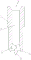
Fig. 1 is a structural representation of the present utility model;
Fig. 2 is a user mode structural representation of the present utility model.
Among the figure: 1-nozzle head body, 2-nozzle head cavity, 3-charging aperture, 4-shower nozzle, the 5-vertebra that leads, 6-discharging opening, 7-nozzle body, 8-nozzle chambers, 9-die cavity, 10-sprue.
The specific embodiment
As shown in Figure 1, the utility model discloses a kind of Nozzle for Mould with Hot Flow Channel head, comprise a nozzle head body 1, the nozzle head cavity 2 that has a up/down perforation on the axle center of described nozzle head body 1, the upper end of described nozzle head cavity is a charging aperture 3, its innovative point is that mainly the lower end of described nozzle head body 1 is a shower nozzle 4 that is dome shape, the sphere centre of described shower nozzle 4 has the tip vertebra shape guiding vertebra 5 down of an evagination, the periphery of described guiding vertebra 5 has several and is the equally distributed discharging opening 6 of level, and described discharging opening 6 is connected with nozzle head cavity 2.
As shown in Figure 2, when Nozzle for Mould with Hot Flow Channel head of the present utility model is worked, nozzle head body 1 is fixed on nozzle chambers 8 bottoms of a nozzle body 7, described shower nozzle 4 offsets with the sprue 10 of die cavity 9, injection molding material flows out the sprue 10 that injects die cavities 9 from the charging aperture 3 nozzle head cavity 2 of flowing through from discharging opening 6.The shape of the shower nozzle 4 of dome shape and the sprue 10 of the die cavity 9 that is the concave spherical surface shape needs basic identical, like this, makes that the gap between the sprue 10 of shower nozzle 4 and die cavity 9 is minimum.The effect of guiding vertebra 5 is to make injection molding material that individual guide effect be arranged when flowing into sprue 10.
The outer surface of the axis of the described discharging opening 6 of Nozzle for Mould with Hot Flow Channel head of the present utility model and the shower nozzle 4 of dome shape is perpendicular.Making discharging opening 6 be umbrella distributes.Make the flow distribution of injection molding material more even.
Claims (2)
1. Nozzle for Mould with Hot Flow Channel head, comprise a nozzle head body (1), the nozzle head cavity (2) that has a up/down perforation on the axle center of described nozzle head body (1), the upper end of described nozzle head cavity is charging aperture (3), the lower end that it is characterized in that described nozzle head body (1) is a shower nozzle (4) that is dome shape, the sphere centre of described shower nozzle (4) has the tip vertebra shape guiding vertebra (5) down of an evagination, the periphery of described guiding vertebra (5) has several and is the equally distributed discharging opening of level (6), and described discharging opening (6) is connected with nozzle head cavity (2).
2. Nozzle for Mould with Hot Flow Channel head according to claim 1 is characterized in that the outer surface of shower nozzle (4) of the axis of described discharging opening (6) and dome shape is perpendicular.
Priority Applications (1)
| Application Number | Priority Date | Filing Date | Title |
|---|---|---|---|
| CN 201220723007 CN203092922U (en) | 2012-12-25 | 2012-12-25 | Nozzle head of hot runner mold |
Applications Claiming Priority (1)
| Application Number | Priority Date | Filing Date | Title |
|---|---|---|---|
| CN 201220723007 CN203092922U (en) | 2012-12-25 | 2012-12-25 | Nozzle head of hot runner mold |
Publications (1)
| Publication Number | Publication Date |
|---|---|
| CN203092922U true CN203092922U (en) | 2013-07-31 |
Family
ID=48844361
Family Applications (1)
| Application Number | Title | Priority Date | Filing Date |
|---|---|---|---|
| CN 201220723007 Expired - Fee Related CN203092922U (en) | 2012-12-25 | 2012-12-25 | Nozzle head of hot runner mold |
Country Status (1)
| Country | Link |
|---|---|
| CN (1) | CN203092922U (en) |
Cited By (2)
| Publication number | Priority date | Publication date | Assignee | Title |
|---|---|---|---|---|
| CN104369314A (en) * | 2014-11-10 | 2015-02-25 | 苏州洛世奇热流道科技有限公司 | High-temperature-resistant pin-point gate hot runner nozzle |
| CN107876220A (en) * | 2016-09-29 | 2018-04-06 | 上海康文喷咀机械有限公司 | A kind of seperator shower nozzle |
-
2012
- 2012-12-25 CN CN 201220723007 patent/CN203092922U/en not_active Expired - Fee Related
Cited By (2)
| Publication number | Priority date | Publication date | Assignee | Title |
|---|---|---|---|---|
| CN104369314A (en) * | 2014-11-10 | 2015-02-25 | 苏州洛世奇热流道科技有限公司 | High-temperature-resistant pin-point gate hot runner nozzle |
| CN107876220A (en) * | 2016-09-29 | 2018-04-06 | 上海康文喷咀机械有限公司 | A kind of seperator shower nozzle |
Similar Documents
| Publication | Publication Date | Title |
|---|---|---|
| WO2006074181A3 (en) | Injection molding system for injection molding a plurality of materials | |
| CN203092922U (en) | Nozzle head of hot runner mold | |
| KR101292498B1 (en) | Nozzle which composes vent block | |
| CN205272512U (en) | Injection mold | |
| CN202726019U (en) | Die-casting mould | |
| CN207578963U (en) | The injection mold of built-in mixed flow | |
| CN203899800U (en) | Mixed gas ejector | |
| CN203792642U (en) | Injection mold flowing channel structure | |
| CN204505711U (en) | A kind of Split type die sprue bush | |
| CN103395173B (en) | A kind of PP large transfusion bottle preform mould entering glue based on three-clove style | |
| KR102294653B1 (en) | injection molding tool | |
| CN203957274U (en) | The quick colour changing nozzle head of hot runner pin-point gate | |
| CN204585719U (en) | A kind of silica gel product shaping cold runner nozzle-type mould | |
| CN206140826U (en) | Plastic pours into piece and plastic mould into | |
| CN207495928U (en) | A kind of transfusion bottle injection mold | |
| CN203665842U (en) | Main runner flow division mechanism for die | |
| CN202378246U (en) | Improved structure of hot runner die | |
| CN208343329U (en) | A kind of handle mold | |
| CN201736407U (en) | Injection mold zoning filling hot runner plate | |
| CN209738201U (en) | Injection molding flow distribution plate structure | |
| CN201002326Y (en) | Slide fastener shaping apparatus | |
| CN202716443U (en) | Centre preventing bubbles from generating on surface of base of ejection molding connector | |
| CN204149446U (en) | Side is entered to water hot runner mould | |
| CN208232233U (en) | A kind of hot runner mould | |
| CN208497556U (en) | A kind of injection mould |
Legal Events
| Date | Code | Title | Description |
|---|---|---|---|
| C14 | Grant of patent or utility model | ||
| GR01 | Patent grant | ||
| CF01 | Termination of patent right due to non-payment of annual fee |
Granted publication date: 20130731 Termination date: 20151225 |
|
| EXPY | Termination of patent right or utility model |