CN203067801U - Butterfly valve with inflatable sealing valve plate - Google Patents
Butterfly valve with inflatable sealing valve plate Download PDFInfo
- Publication number
- CN203067801U CN203067801U CN 201320053685 CN201320053685U CN203067801U CN 203067801 U CN203067801 U CN 203067801U CN 201320053685 CN201320053685 CN 201320053685 CN 201320053685 U CN201320053685 U CN 201320053685U CN 203067801 U CN203067801 U CN 203067801U
- Authority
- CN
- China
- Prior art keywords
- valve
- plate
- ring
- butterfly valve
- surface plate
- Prior art date
- Legal status (The legal status is an assumption and is not a legal conclusion. Google has not performed a legal analysis and makes no representation as to the accuracy of the status listed.)
- Withdrawn - After Issue
Links
Images


Abstract
The utility model relates to a butterfly valve with an inflatable sealing valve plate, belongs to the technical field of butterfly valves, and aims at providing a butterfly valve with a good sealing effect and low sealing and opening resistances. The butterfly valve adopts the technical scheme that the valve plate of the butterfly valve consists of an upper spherical surface plate, a lower spherical surface plate, an elastic ring and a sealing seat ring, wherein curvature radii of the upper spherical surface plate and the lower spherical surface plate are located on the same side; sphere centers of spherical surfaces are opposite in the same straight line on the same side; the elastic ring and the sealing seat ring are connected between the peripheries of the upper spherical surface plate and the lower spherical surface plate in parallel in a surrounding manner; and an air source joint is communicated with a cavity formed among the upper spherical surface plate, the lower spherical surface plate, the elastic ring and the sealing seat ring of the valve plate by a vent duct. According to the butterfly valve, a hard sealing structure of the traditional butterfly valve is changed, the butterfly valve adopts the inflatable hollow valve plate in a double-layer structure, and the whole working process of the valve has a qualitative change. The sealing precision of the butterfly valve can reach a very high level. The butterfly valve is ingenious in design, a new style is developed, the sealing design of the butterfly valve is innovated, unexpected good effects are achieved, and the butterfly valve is worth of popularization and application.
Description
Technical field
The utility model relates to the seal butterfly valve that a kind of industrial pipeline uses, and belongs to the butterfly valve technical field.
Background technique
Butterfly valve is a kind of valve that is widely used in industries such as metallurgy, building materials, oil, chemical industry, is indispensable and irreplaceable product in the present industrial production.The major function of butterfly valve is the break-make of control pipeline, requirement for butterfly valve is, medium when opening in the pipeline is smooth and easy to be passed through, reach reliable sealing, function-stable when closed, to stand rugged environment be high temperature, bonding, corrode and wash away, and possesses reliable sealing performances such as anti-corrosion, wear-resisting, high temperature resistant.
In butterfly valve, airtight butterfly valve with high content of technology, strict, of many uses.Traditional seal butterfly valve is that valve rod drives the valve plate rotation, and interference fit enforcement pipeline is airtight relatively between the dependence sealing pair.When being closed to final position, need transmission device to give the great moment of valve rod and just can finish, its starting torque normally ventilate butterfly valve 8-10 doubly.Because hard sealing is confronting the tough with toughnees between metal and the metal, finishes driving fit in rotation, the technological requirement height, manufacture difficulty is big, is difficult to produce high quality A, the excellent product of B level.
Simultaneously, seal butterfly valve is in the opening and closing process, because manifold pressure height, seal pressure is big, and unlatching moment is also big relatively, and this powerful friction not only brings difficulty to manufacturing, the sealing pair damage is also quite serious, not only needing often maintenance and replacing, also greatly reduce the working life of seal butterfly valve, also is an insoluble major issue of present seal butterfly valve.
The model utility content
Technical problem to be solved in the utility model provides a kind of butterfly valve with gas-flow closure valve plate, and this butterfly valve seal is effective, does not exist spin friction to cooperate the large drag forces that produces, and sealing and unlatching are easy, and increase working life greatly.
The technological scheme that solves the problems of the technologies described above is:
A kind of butterfly valve with gas-flow closure valve plate, comprise valve body in its formation, valve plate, valve rod, valve seals, be fixedly connected with bearing on the valve plate, bearing is connected with valve rod by taper pin, its improvements are, valve plate is by last spherical plate, the lower peripheral surface plate, elastic ring, seal holder ring is formed, last spherical plate and lower peripheral surface plate radius of curvature are at homonymy, last spherical plate is relative on the same straight line of homonymy with the sphere centre of lower peripheral surface plate, elastic ring and seal holder ring are parallel around between the circumference that is connected spherical plate and lower peripheral surface plate, last spherical plate is connected with elastic ring, elastic ring is connected with seal holder ring, seal holder ring is connected with the lower peripheral surface plate, and gas source connector is by the last spherical plate of vent cap and valve plate, the lower peripheral surface plate, elastic ring, the cavity that forms between the seal holder ring is connected.
Above-mentioned butterfly valve with gas-flow closure valve plate, described seal holder ring is connected by bolt with the lower peripheral surface plate, and the outer ring of seal holder ring is around being equipped with seal ring, and seal ring is corresponding with valve seals.
Above-mentioned butterfly valve with gas-flow closure valve plate, in the described bearing and in the valve rod vent cap that is connected is arranged, gas source connector is installed in an end of valve rod, and the vent cap in gas source connector and the valve rod is connected, and the vent cap in the bearing is connected with the valve plate cavity by last spherical plate.
Above-mentioned butterfly valve with the moving valve plate of gas-flow closure, described elastic ring is stainless steel coil, and its cross section is semicircular ring, and the two ends of semicircular ring are connected with seal holder ring with last spherical plate respectively.
Usefulness of the present utility model is:
The utility model has changed the hard sealing structure of traditional butterfly valve, adopts double-deck hollow valve plate, and inflation back valve plate expands in the valve plate cavity, and the valve plate seal ring moves sealing pair is effectively closed, and it is closed to finish blocking-up.This sealing configuration does not exist spin friction to cooperate the large drag forces that produces, during valve open, inflation pressure let out remove, the elastic ring energy reserve discharges, and the valve plate seal ring can break away from seal ring smoothly, with valve open, thereafter valve rotates to out the position, and its moment also only is equivalent to the size of a ventilation butterfly valve, compares with traditional hard seal butterfly valve, driving torque of the present utility model is saved 8-10 doubly, and the variation of matter has taken place the entire work process of valve.Butterfly valve seal precision of the present utility model can reach high level.The utility model design is ingenious, has changed the conventional thought of butterfly valve seal structure, and is off the beaten track, is the innovation of butterfly valve seal design, obtained beyond thought good result, is worthy of popularization.
Description of drawings
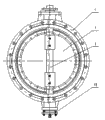
Fig. 1 is structural representation of the present utility model;
Fig. 2 is the side view of Fig. 1;
Fig. 3 is the front view of valve plate;
Fig. 4 is the A-A sectional view of Fig. 3.
Mark is as follows among the figure: valve body 1, valve plate 2, valve rod 3, last spherical plate 4, lower peripheral surface plate 5, elastic ring 6, seal holder ring 7, bearing 8, valve seals 9, gas source connector 10, seal ring 11, vent cap 12.
Embodiment
The utility model is made up of valve body 1, valve plate 2, valve rod 3, valve seals 9, is fixedly connected with bearing 8 on the valve plate 2, and bearing 8 is connected with valve rod 3 by taper pin.
Show among the figure, improvements of the present utility model are that the valve plate 2 of butterfly valve is the double-layer hollow form, is made up of the spherical panel of upper and lower two different curvature radius, be connected with stainless steel elastic ring 6 and seal holder ring 7 between last spherical plate 4 and the lower peripheral surface plate 5, seal ring 11 is housed on the seal holder ring 7.
Show among the figure, last spherical plate 4 is relative with lower peripheral surface plate 5 male and female faces, the sphere centre of last spherical plate 4 and lower peripheral surface plate 5 is on the same straight line of homonymy, elastic ring 6 and seal holder ring 7 are parallel around between the circumference that is connected spherical plate 4 and lower peripheral surface plate 5, last spherical plate 4 is connected with elastic ring 6, elastic ring 6 is connected with seal holder ring 7, and seal holder ring 7 is connected with lower peripheral surface plate 5, forms the cavity of a sealing between last spherical plate 4, lower peripheral surface plate 5, elastic ring 6, the seal holder ring 7.
Show among the figure that seal holder ring 7 and lower peripheral surface plate 5 are connected by bolt, the outer ring of seal holder ring 7 is around being equipped with seal ring 11, and seal ring 11 is corresponding with valve seals 9.After the inflation, lower peripheral surface plate 5 can produce and expand in the valve plate cavity, and the outer ring of seal holder ring 7 vertically moves around the seal ring of installing 11 is outer mutually, closely contacts with valve seals 9, reaches the effect of sealing.
Show among the figure that elastic ring 6 is stainless steel coil, its cross section is semicircular ring, and the two ends of semicircular ring are connected with seal holder ring 7 with last spherical plate 4 respectively.
Show among the figure, in the bearing 8 and in the valve rod 3 vent cap 12 that is connected is arranged, source of the gas connects 10 ends that are installed in valve rod 3, and the vent cap 12 in gas source connector 10 and the valve rod 3 is connected, and the vent caps 12 in the bearing 8 are connected with the valve plate cavity by last spherical plate 4.Pressurized air enters the valve plate cavity by gas source connector 10, vent cap 12, and drive valve plate 2 is opened and be closed.
Working procedure of the present utility model is as follows:
Valve closing action: when valve plate 2 forwards off-position under valve actuator drives, limited by limiting stopper, be parked in pre-sealed position, pressure medium is by 10 pairs of valve plates of gas source connector, 2 inflations (liquid) on the valve rod 3, valve plate 2 expands under the pressure medium effect, lower peripheral surface plate 5 pulling elastic rings 6 drive seal rings 11 vertical displacements, meet with valve seals 9 in sealing pair, the blocking tube track media, finish the valve closing function.When valve plate 2 expands, elastic ring 6 stressed energy storage.
The valve open action: when the valve platform sends the valve open instruction, pressure medium pressure release, the lower peripheral surface plate 5 no pressure support of valve plate 2, elastic ring 6 energy storage discharge, band lower peripheral surface plate 5, seal holder ring 7 and seal ring 11 returns, the pipeline medium conducting, transmission device band valve plate 2 rotates to out the position.Finish valve open.
Claims (4)
1. butterfly valve with gas-flow closure valve plate, comprise valve body (1) in its formation, valve plate (2), valve rod (3), valve seals (9), be fixedly connected with bearing (8) on the valve plate (2), bearing (8) is connected with valve rod (3) by taper pin, it is characterized in that: valve plate (2) is by last spherical plate (4), lower peripheral surface plate (5), elastic ring (6), seal holder ring (7) is formed, last spherical plate (4) and lower peripheral surface plate (5) radius of curvature are in the same side, last spherical plate (4) is relative on the same straight line of homonymy with the sphere centre of sphere of lower peripheral surface plate (5), elastic ring (6) and seal holder ring (7) are parallel around between the circumference that is connected spherical plate (4) and lower peripheral surface plate (5), last spherical plate (4) is connected with elastic ring (6), elastic ring (6) is connected with seal holder ring (7), seal holder ring (7) is connected with lower peripheral surface plate (5), and gas source connector (10) is by the last spherical plate (4) of vent cap (12) with valve plate (2), lower peripheral surface plate (5), elastic ring (6), the cavity that forms between the seal holder ring (7) is connected.
2. the butterfly valve with gas-flow closure valve plate according to claim 1, it is characterized in that: described seal holder ring (7) is connected by bolt with lower peripheral surface plate (5), the outer ring of seal holder ring (7) is around being equipped with seal ring (11), and seal ring (11) is corresponding with valve seals (9).
3. the butterfly valve with gas-flow closure valve plate according to claim 1 and 2, it is characterized in that: in the described bearing (8) and in the valve rod (3) vent cap (12) that is connected is arranged, gas source connector (10) is installed in an end of valve rod (3), vent cap (12) in gas source connector (10) and the valve rod (3) is connected, and the vent cap (12) in the bearing (8) is connected with the valve plate cavity by last spherical plate (4).
4. the butterfly valve with gas-flow closure valve plate according to claim 3, it is characterized in that: described elastic ring (6) is stainless steel coil, and its cross section is semicircular ring, and the two ends of semicircular ring are connected with seal holder ring (7) with last spherical plate (4) respectively.
Priority Applications (1)
| Application Number | Priority Date | Filing Date | Title |
|---|---|---|---|
| CN 201320053685 CN203067801U (en) | 2013-01-31 | 2013-01-31 | Butterfly valve with inflatable sealing valve plate |
Applications Claiming Priority (1)
| Application Number | Priority Date | Filing Date | Title |
|---|---|---|---|
| CN 201320053685 CN203067801U (en) | 2013-01-31 | 2013-01-31 | Butterfly valve with inflatable sealing valve plate |
Publications (1)
| Publication Number | Publication Date |
|---|---|
| CN203067801U true CN203067801U (en) | 2013-07-17 |
Family
ID=48766587
Family Applications (1)
| Application Number | Title | Priority Date | Filing Date |
|---|---|---|---|
| CN 201320053685 Withdrawn - After Issue CN203067801U (en) | 2013-01-31 | 2013-01-31 | Butterfly valve with inflatable sealing valve plate |
Country Status (1)
| Country | Link |
|---|---|
| CN (1) | CN203067801U (en) |
Cited By (2)
| Publication number | Priority date | Publication date | Assignee | Title |
|---|---|---|---|---|
| CN103075526A (en) * | 2013-01-31 | 2013-05-01 | 石家庄市长宏阀门有限公司 | Butterfly valve with inflation seal valve plate |
| CN110332324A (en) * | 2019-05-06 | 2019-10-15 | 中国建筑科学研究院有限公司 | Intelligent control's biological airtight valve |
-
2013
- 2013-01-31 CN CN 201320053685 patent/CN203067801U/en not_active Withdrawn - After Issue
Cited By (2)
| Publication number | Priority date | Publication date | Assignee | Title |
|---|---|---|---|---|
| CN103075526A (en) * | 2013-01-31 | 2013-05-01 | 石家庄市长宏阀门有限公司 | Butterfly valve with inflation seal valve plate |
| CN110332324A (en) * | 2019-05-06 | 2019-10-15 | 中国建筑科学研究院有限公司 | Intelligent control's biological airtight valve |
Similar Documents
| Publication | Publication Date | Title |
|---|---|---|
| CN203836269U (en) | Ultra-low-temperature no-friction top entry type fixing ball valve | |
| CN203067801U (en) | Butterfly valve with inflatable sealing valve plate | |
| CN103075526B (en) | Butterfly valve with inflation seal valve plate | |
| CN201202828Y (en) | Pneumatic diaphragm valve | |
| CN204437296U (en) | Embedded forging Y type is without bonnet stop valve | |
| CN200975505Y (en) | Pneumatic brake valve with boosting unlock function | |
| CN201288846Y (en) | M-shaped pneumatic straight-through diaphragm valve | |
| CN204420200U (en) | Cylinder-rotating three-way diverter valve | |
| CN202195115U (en) | Orbit plug valve capable of being on-line maintained | |
| CN203532800U (en) | High sealing performance valve | |
| CN201302007Y (en) | Corrugated pipe stop valve | |
| CN2916288Y (en) | 3D eccentric two-way metallic hard sealing butterfly valve | |
| CN203214872U (en) | Novel movable sealing device | |
| CN207750519U (en) | Tire formula compensation sealing structure on valve | |
| CN202852035U (en) | Gate valve | |
| CN202790724U (en) | Check valve with guide cylinder | |
| CN206290813U (en) | A kind of pneumatic dog angle pedestal valve | |
| CN206234458U (en) | A kind of anti-lock flue regulating butterfly valve | |
| CN206206638U (en) | A kind of oscillatory valve | |
| CN202441902U (en) | Novel pneumatic butterfly valve | |
| CN2309476Y (en) | Bellows stop valve | |
| CN203214915U (en) | Steel casting of gas turbine | |
| CN202768872U (en) | Manual globe valve | |
| CN2403953Y (en) | Liquid, air pressure self-balance stop valve | |
| CN203258100U (en) | Mounted-type ball valve capable of being dismounted and mounted on line and achieving two-way sealing |
Legal Events
| Date | Code | Title | Description |
|---|---|---|---|
| C14 | Grant of patent or utility model | ||
| GR01 | Patent grant | ||
| AV01 | Patent right actively abandoned |
Granted publication date: 20130717 Effective date of abandoning: 20140813 |
|
| RGAV | Abandon patent right to avoid regrant |