CN203066883U - Air pipe suspension type gas lift reverse circulation drilling rod - Google Patents
Air pipe suspension type gas lift reverse circulation drilling rod Download PDFInfo
- Publication number
- CN203066883U CN203066883U CN 201320054479 CN201320054479U CN203066883U CN 203066883 U CN203066883 U CN 203066883U CN 201320054479 CN201320054479 CN 201320054479 CN 201320054479 U CN201320054479 U CN 201320054479U CN 203066883 U CN203066883 U CN 203066883U
- Authority
- CN
- China
- Prior art keywords
- drilling rod
- single wall
- suspension type
- reverse circulation
- air pipe
- Prior art date
- Legal status (The legal status is an assumption and is not a legal conclusion. Google has not performed a legal analysis and makes no representation as to the accuracy of the status listed.)
- Expired - Fee Related
Links
Images


Abstract
The utility model discloses an air pipe suspension type gas lift reverse circulation drilling rod which solves the problem that the strength of the existing air pipe suspension type gas lift reverse circulation drilling rod is insufficient due to a structural design defect. The air pipe suspension type gas lift reverse circulation drilling rod adopts the technical scheme that the air pipe suspension type gas lift reverse circulation drilling rod comprises a single wall drilling rod and an air pipe positioned in the single wall drilling rod, wherein the single wall drilling rod is formed by threaded connection of a plurality of single wall drilling rod units; each single wall drilling rod unit consists of a pipe body, and a female adapter and a male adapter that are welded at the two ends of the pipe body; particularly, external diameters of the pipe bodies are equal; internal diameters of the pipe bodies are tapered; reinforcement sections with wall thicknesses being increased are arranged at the two ends of the pipe bodies; and transition platforms are arranged among the reinforcement sections and the middle parts of the pipe bodies. According to the air pipe suspension type gas lift reverse circulation drilling rod, structures of the pipe bodies are improved, and sizes of the pipe bodies are optimized, so that the tensile strength and the fatigue strength of the single wall drilling rod are improved effectively; ratios of the external diameters of the female adapters to the internal diameters of the male adapters are increased, and threads in accordance with API (American Petroleum Institute) standards are adopted, so that the strength of the female adapters and the strength of the male adapters are improved; and the interchangeability and the reparability of the threads are ensured.
Description
Technical field
The utility model relates to a kind of drilling rig, specifically a kind of airduct suspension type gaslift reverse circulation drilling bar.
Background technology
Airduct suspension type gaslift reverse circulation drilling bar is a kind of novel drilling rod that is applied to gas lift reverse circulation drilling process, it is made up of single wall drilling rod and airduct, the single wall drilling rod is made up of the single wall drilling rod unit that a plurality of dependence are threaded, each single wall drilling rod unit is made up of body and the female adapter, the male connection that are welded on the body two ends, and airduct hangs in the single wall drilling rod hole.When creeping into, the single wall drilling rod is used for transmitting moment of torsion, rotary drilling, airduct injects single wall drill pipe bore mud for delivery of pressure-air, form mud, Air mixing body, mixture is lower with respect to the mud balance between single wall drilling rod and the hole wall, form negative pressure, upwards flow out through the air water tap from the inside of single wall drilling rod thereby make the outer mud of single wall drilling rod behind the drill bit bottom, carry the rock slag, reach the purpose of efficiently creeping into.Continue to use the single wall jackrod structure of foreign technology always and when long-term the use, find to have following problems: gauge structures such as the body endoporus employing of each single wall drilling rod unit, bigger moment of torsion is born at the body both ends during drilling construction, causes fracture because of strength deficiency easily; A little less than the wall thickness relative thin of female adapter, male connection, intensity is difficult for guaranteeing occurring easily fracture or thread gluing during boring; Nonstandard screw thread is adopted in female adapter, male connection, has caused screw thread reparation and interchangeability to be difficult for guaranteeing.
The utility model content
The utility model is used for solving the defective of above-mentioned prior art, provides a kind of and improves intensity and the airduct suspension type gaslift reverse circulation drilling bar in application life by architecture advances.
It is as follows to address the above problem the technical scheme that adopts:
A kind of airduct suspension type gaslift reverse circulation drilling bar, it is made up of single wall drilling rod and the airduct that is positioned at the single wall drilling rod, the single wall drilling rod is made up of through being threaded a plurality of single wall drilling rod units, each single wall drilling rod unit is made of body and the female adapter, the male connection that are welded on the body two ends, special feature is: described body external diameter is equal diameter, internal diameter of tube body is reducing, is provided with the reinforcement section that wall thickness increases at the body two ends, strengthens being provided with transition bench between section and the body middle part.
Above-mentioned airduct suspension type gaslift reverse circulation drilling bar, the ratio of the wall thickness dimension B of described reinforcement section and body wall thickness dimension b is: B/b=1.8-2.2, the length of described transition bench is the 80-120 millimeter.
Above-mentioned airduct suspension type gaslift reverse circulation drilling bar, the D outer diameter of described female adapter, male connection and the ratio of inner diameter d are D/d=1.8-2.0.
Above-mentioned airduct suspension type gaslift reverse circulation drilling bar, described female adapter is two shoulder taper pipe threads or common taper pipe thread with the type that is threaded of male connection.
The utility model improves because the structure design defective causes the problem of local strength's deficiency at existing airduct suspension type gaslift reverse circulation drilling bar, the transition bench that the reinforcement section that improves intensity is set and avoids stress to concentrate at the weak link place, body two ends of single wall drilling rod unit, by the dimensionally-optimised design to reinforcement section and transition bench, cooperate Technology for Heating Processing, improved tensile strength and the fatigue strength of single wall drilling rod effectively; The utility model has also improved the ratio of female adapter, male connection external diameter and inner diameter values, the screw thread that meets the API standard is adopted in female adapter, male connection, this improves when improving the internal and external screw thread strength of joint, has guaranteed interchangeability and the recoverability of screw thread.
Description of drawings
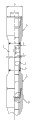
Fig. 1 is structural representation of the present utility model;
Fig. 2 is the single wall drilling rod unit structural representation that adopts common taper pipe thread;
Fig. 3 is Fig. 2 A place partial enlarged view;
Fig. 4 is the single wall drilling rod unit structural representation that adopts two shoulder taper pipe threads;
Fig. 5 is Fig. 4 B place partial enlarged view.
Each parts label is as follows among the figure: 1. single wall drilling rod; 2. airduct; 3. body; 4. female adapter; 5. male connection; 5-1. common taper pipe thread; 5-2. two shoulder taper pipe threads; 6. strengthen section; 7. transition bench.
The specific embodiment
Referring to Fig. 1, the utility model single wall drilling rod 1 and airduct 2 are formed, and airduct 2 hangs in the hole of single wall drilling rod 1.The single wall drilling rod is made up of through being threaded a plurality of single wall drilling rod units, and each single wall drilling rod unit is made of body 3 and the female adapter 4, the male connection 5 that are welded on the body two ends.
Referring to Fig. 1, Fig. 2, Fig. 4, in drilling construction, the body two ends are flimsy weak part, carried out following improvement at this weak part the utility model: the external diameter of body 3 adopts equal diameter, internal diameter of tube body is reducing, be provided with the reinforcement section 6 that wall thickness increases at the body two ends, strengthen section by the increase of wall thickness and corresponding Technology for Heating Processing, play the effect that improves tensile strength and fatigue strength.Increase based on strengthening the section wall thickness, cause that for avoiding size sudden change place stress concentrates, strengthening being provided with transition bench 7 between section and the body middle part, strengthen being connected through transition bench in the middle part of section and the body.Strengthening the wall thickness dimension B of section 6 and the ratio of body wall thickness dimension b is: B/b=1.8-2.2, the length of transition bench 7 is the 80-120 millimeter.
Referring to Fig. 2, Fig. 3, the utility model calculates through the bending strength ratio to drilling rod, outside dimension to female adapter, male connection improves, the D outer diameter of female adapter, male connection and the ratio of its inner diameter d: D/d=1.8-2.0, the D outer diameter of female adapter, male connection and inner diameter d equate respectively.Above-mentioned improvement, the external diameter of the female adapter that scales up, male connection, when having improved the big diameter borehole construction, internal and external threads connecting portion intensity is difficult for guaranteeing, the phenomenon of easy fracture and thread gluing.In addition, the screw thread that meets API standard (American Petroleum Institute authenticates) is adopted at the screw thread position of female adapter, male connection, has guaranteed interchangeability and the recoverability of screw thread.
Referring to Fig. 2-4, described female adapter 4 and the type that is threaded of male connection 5 are two shoulder taper pipe thread 5-2 shown in Figure 5, or common taper pipe thread 5-1 shown in Figure 3.Two shoulder taper pipe thread 5-2 screw threads have two sealing shoulder, and this screw thread can improve sealing performance and the torsional strength of tool joint.
Claims (4)
1. airduct suspension type gaslift reverse circulation drilling bar, it is made up of single wall drilling rod (1) and the airduct (2) that is positioned at the single wall drilling rod, the single wall drilling rod is made up of through being threaded a plurality of single wall drilling rod units, each single wall drilling rod unit is made of body (3) and the female adapter (4), male connection (5) that are welded on the body two ends, it is characterized in that: described body (3) external diameter is equal diameter, internal diameter of tube body is reducing, be provided with the reinforcement section (6) that wall thickness increases at the body two ends, strengthen being provided with transition bench (7) between section and the body middle part.
2. airduct suspension type gaslift reverse circulation drilling bar according to claim 1 is characterized in that: describedly strengthen the wall thickness dimension B of section (6) and the ratio of body wall thickness dimension b is: B/b=1.8-2.2, the length of described transition bench (7) is the 80-120 millimeter.
3. airduct suspension type gaslift reverse circulation drilling bar according to claim 2, it is characterized in that: the D outer diameter of described female adapter, male connection and the ratio of inner diameter d are D/d=1.8-2.0.
4. airduct suspension type gaslift reverse circulation drilling bar according to claim 3 is characterized in that: described female adapter (4) is two shoulder taper pipe threads (5-2) or common taper pipe thread (5-1) with the type that is threaded of male connection (5).
Priority Applications (1)
| Application Number | Priority Date | Filing Date | Title |
|---|---|---|---|
| CN 201320054479 CN203066883U (en) | 2013-01-31 | 2013-01-31 | Air pipe suspension type gas lift reverse circulation drilling rod |
Applications Claiming Priority (1)
| Application Number | Priority Date | Filing Date | Title |
|---|---|---|---|
| CN 201320054479 CN203066883U (en) | 2013-01-31 | 2013-01-31 | Air pipe suspension type gas lift reverse circulation drilling rod |
Publications (1)
| Publication Number | Publication Date |
|---|---|
| CN203066883U true CN203066883U (en) | 2013-07-17 |
Family
ID=48765693
Family Applications (1)
| Application Number | Title | Priority Date | Filing Date |
|---|---|---|---|
| CN 201320054479 Expired - Fee Related CN203066883U (en) | 2013-01-31 | 2013-01-31 | Air pipe suspension type gas lift reverse circulation drilling rod |
Country Status (1)
| Country | Link |
|---|---|
| CN (1) | CN203066883U (en) |
Cited By (2)
| Publication number | Priority date | Publication date | Assignee | Title |
|---|---|---|---|---|
| CN107461158A (en) * | 2017-08-31 | 2017-12-12 | 山西风雷钻具有限公司 | High strength friction welds heavy weight drill pipe |
| US10337249B2 (en) | 2017-02-04 | 2019-07-02 | Jason A Hatfield | Drilling wells with air |
-
2013
- 2013-01-31 CN CN 201320054479 patent/CN203066883U/en not_active Expired - Fee Related
Cited By (2)
| Publication number | Priority date | Publication date | Assignee | Title |
|---|---|---|---|---|
| US10337249B2 (en) | 2017-02-04 | 2019-07-02 | Jason A Hatfield | Drilling wells with air |
| CN107461158A (en) * | 2017-08-31 | 2017-12-12 | 山西风雷钻具有限公司 | High strength friction welds heavy weight drill pipe |
Similar Documents
| Publication | Publication Date | Title |
|---|---|---|
| CN201705226U (en) | Integral type double-shoulder sulfur resistant drill rod | |
| CN202946041U (en) | Zigzag air-sealed oil well pipe thread joint structure | |
| CN202338212U (en) | Continuous oil pipe connector | |
| CN202755907U (en) | Drill pipe structure with big bit port | |
| CN204024505U (en) | High tensile is anti-pushes away directional traversing drill rod special | |
| CN201322148Y (en) | High performance oil pipe hermetic seal threaded connection structure | |
| CN201322147Y (en) | Connection structure for small-clearance collar and casing threads | |
| CN203066883U (en) | Air pipe suspension type gas lift reverse circulation drilling rod | |
| CN202039786U (en) | Connecting structure for high-pressure well completion oil pipe | |
| CN101899953A (en) | Thread joint structure for high-performance oil casing | |
| CN201574696U (en) | Large-caliber fast screwing-up sleeve thread connecting structure | |
| CN2764923Y (en) | Double shoulder hermetic sealing drill pipe joint | |
| CN201751527U (en) | Hermetic seal drill pipe joint with good torsion resistance performance | |
| CN204082029U (en) | A kind of oil bushing threaded connector of high torque resistant high leakproofness | |
| CN201756919U (en) | Threaded connection structure for operation oil pipe | |
| CN204040936U (en) | The female adapter of petroleum pipeline direct linkage type | |
| CN203796182U (en) | Triangular-ribbed drill pipe for coal mine gallery drilling and drilling mud removal | |
| CN203403831U (en) | Direct-connecting oil casing pipe threaded connector | |
| CN203403830U (en) | Aluminum alloy drill pipe structure for wire-line coring drilling | |
| CN101864906A (en) | Bending-resistant oil casing threaded connection structure | |
| CN201763267U (en) | Anti-bending oil sleeve threaded connection structure | |
| CN205936433U (en) | Oil conduit screw connection structure | |
| CN217558271U (en) | Connecting mechanism of elliptical continuous sucker rod | |
| CN202064850U (en) | Double-flange threaded connector | |
| CN204738758U (en) | Special screwed joint is used to HTHP oil gas well |
Legal Events
| Date | Code | Title | Description |
|---|---|---|---|
| C14 | Grant of patent or utility model | ||
| GR01 | Patent grant | ||
| CF01 | Termination of patent right due to non-payment of annual fee |
Granted publication date: 20130717 Termination date: 20160131 |
|
| EXPY | Termination of patent right or utility model |