CN203020505U - Drive mechanism of bicycle and bicycle with the same - Google Patents
Drive mechanism of bicycle and bicycle with the same Download PDFInfo
- Publication number
- CN203020505U CN203020505U CN 201220545429 CN201220545429U CN203020505U CN 203020505 U CN203020505 U CN 203020505U CN 201220545429 CN201220545429 CN 201220545429 CN 201220545429 U CN201220545429 U CN 201220545429U CN 203020505 U CN203020505 U CN 203020505U
- Authority
- CN
- China
- Prior art keywords
- bicycle
- wheel
- flywheels
- transmission device
- trailing wheel
- Prior art date
- Legal status (The legal status is an assumption and is not a legal conclusion. Google has not performed a legal analysis and makes no representation as to the accuracy of the status listed.)
- Expired - Fee Related
Links
Images
Abstract
The utility model discloses a drive mechanism of a bicycle. The bicycle comprises a frame, a rear wheel and a front wheel, wherein the rear wheel and the front wheel are connected to the frame. The drive mechanism comprises two flywheels which are respectively in drive connection with the rear wheel, two driving belts which are respectively in drive connection with the two flywheels, two pedal plates which are respectively connected with the two driving belts, an upper transition wheel system which is in drive connection with the free ends of the two driving belts on the upper sides of the two flywheels, and a lower transition wheel system which is in drive connection with the free ends of the two driving belts on the lower sides of the two flywheels. By means of the technical scheme, the cycling of power output of a bicycle with one rear wheel can be achieved. In addition, the power output by the human body is even and stable, efficiency is high, and the drive mechanism is suitable for a two-wheel bicycle with one rear wheel or a tricycle with one rear wheel.
Description
Technical field
The utility model relates to a kind of transmission device, particularly a kind of transmission device of bicycle and bicycle.
Background technology
application number is that 201010613216.7 utility model patent discloses a kind of bicycle, comprise vehicle frame, two trailing wheels, the axle of two trailing wheels and at least one front-wheel are in transmission connection, upper left the parting on the right side of described axle is not equipped with a flywheel, be left flywheel and right flywheel, be connected with respectively the Left Drive band that matches on described left flywheel and right flywheel and the moving band of turning right, described left and right driving band the upper end connect by upper cable, and be separately installed with Vehicular left pedal and right steps, described left and right driving band the lower end connect by lower cable, described upper cable and lower cable are walked around respectively top sheave and the lower sheave that is arranged on described vehicle frame free to rotate, free wheels straight line pedaling power system when adopting technique scheme, human body can adopt more comfortable sitting posture, and more laborsaving, indefatigability, but, in the technical program, in the technical program, must adopt two trailing wheels, be only applicable to the three-wheel vehicle of two trailing wheels, or four-wheeled.
The utility model content
For addressing the above problem, the purpose of this utility model is to provide a kind of and is applicable to the two-wheeled cycle of single trailing wheel or is the transmission device of bicycle of the tricycle of single trailing wheel equally.
For achieving the above object, the technical solution of the utility model is: a kind of transmission device of bicycle, described bicycle comprise vehicle frame, are connected in trailing wheel and front-wheel on described vehicle frame, and described transmission device comprises:
Two flywheels are in transmission connection respectively on described trailing wheel;
Two driving bands are in transmission connection respectively to described two flywheels;
Two stretchers are connected on described two driving bands;
Upper transition wheel system, the free end of two driving bands of described two the flywheel upsides that are in transmission connection;
And lower transition wheel system, the free end of two driving bands of described two the flywheel downsides that are in transmission connection.
Preferably, described upper (under) the transition wheel system comprise (under) pulley and upper (under) hawser, described upper (under) free end of transition wheel by two driving bands of upper (under) on described two flywheels of hawser connection (under) side.
Preferably, described two stretchers are connected on two driving bands of described two flywheel upsides or are connected on the upper cable of described upper transition wheel both sides.
Preferably, be provided with overriding clutch between described two flywheels and described trailing wheel.
Preferably, be provided with railroad on described vehicle frame, described two stretchers are slidably connected to respectively on described railroad.
Preferably, described two flywheels are two sprocket wheels, and described two driving bands are two driving chains.
Preferably, described two flywheels are two timing wheels, rule band when described two driving bands are two.
Preferably, described trailing wheel is one, and described two flywheels are connected on the flower-drum of described trailing wheel.
The utility model also provides another technical scheme: a kind of bicycle comprises transmission device as above.
Adopt the beneficial effect of the technical program to be: the utility model provides a kind of transmission device of bicycle, pass through the technical program, can realize the moving in circles of power output of wheel bicycle after, and human body outputting power uniform and stable, efficient is higher, is applicable to the bicycle of a trailing wheel or the three-wheel vehicle of a trailing wheel.
Description of drawings
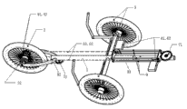
Fig. 1 is the transmission device work schematic diagram of a kind of bicycle of the utility model;
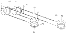
Fig. 2 is the transmission device transmission schematic diagram of a kind of bicycle of the utility model.
Numeral and the represented corresponding component title of letter in figure:
1. vehicle frame 2. trailing wheel 21. trailing wheel flower-drum 3. right sprocket wheel 51. right driving chain 61. Vehicular left pedal 62. right steps 71. top sheave 72. lower sheave 81. upper cable 82. lower cable 9. railroads of Left Drive chain 52. of the left sprocket wheel 42. of front-wheel 41..
The specific embodiment
Below in conjunction with the drawings and specific embodiments, the utility model is described in further detail.
Embodiment 1
Referring to Fig. 1 and Fig. 2, as shown in legend wherein, a kind of transmission device of bicycle, bicycle comprise a vehicle frame 1, are connected in a trailing wheel 2 and two front-wheels 3 on vehicle frame 1, and transmission device comprises:
Two sprocket wheels, namely left sprocket wheel 41 and right sprocket wheel 42, be in transmission connection respectively on trailing wheel 2;
Two driving chains, namely Left Drive chain 51 and right driving chain 52, be in transmission connection respectively to described left and right flywheel 51,52;
Two stretchers, namely Vehicular left pedal 61 and right steps 62, be connected on described left and right driving chain 51,52;
One top sheave 71 connects the free end of the left and right driving chain 51,52 of described left and right sprocket wheel 41,42 upsides by a upper cable 81;
And lower sheave 72, connect the free end of the left and right driving chain 51,52 of described left and right sprocket wheel 41,42 downsides by a lower cable 82.
Left and right stretcher 61,62 is connected on the left and right driving chain 51,52 of left and right sprocket wheel 41,42 upsides.
Be provided with overriding clutch between left and right sprocket wheel 41,42 and trailing wheel 2.
The below introduces principle of work of the present utility model.
When the people of seat of bicycle scrunches Vehicular left pedal 61, the Left Drive chain 51 that is wound on left flywheel 41 drives left sprocket wheel 41 forwards, namely drive trailing wheel flower-drum 21 and trailing wheel 2 rotations, Left Drive chain 51 drives right sprocket wheel 42 counter-rotatings by lower cable 82, and right driving chain 52 drives left flywheel 51 forwards by upper cable 81.
In like manner, when the people of seat of bicycle scrunches right steps 62, the right driving chain 52 that is wound on right sprocket wheel 42 drives right sprocket wheel 42 forwards, namely drive trailing wheel flower-drum 21 and trailing wheel 2 rotations, right driving chain 52 drives left sprocket wheel 42 counter-rotatings by lower cable 82, and Left Drive chain 51 drives right sprocket wheel 42 forwards by upper cable 81.
So move in circles, drive left and right sprocket wheel 41,42 by left and right stretcher 81,82, namely drive trailing wheel flower-drum 21 and trailing wheel 2 rotates, thereby realize the moving in circles of output of power, can either guarantee the power output uniform and stable of human body, and save manpower.
Embodiment 2
Referring to Fig. 1, as shown in legend wherein, all the other are identical with described embodiment 1, and difference is, is provided with railroad 9 on vehicle frame 1, and left and right stretcher 61,62 is connected on railroad 9, makes application of force direction more accurate, and driving efficiency is higher.
All the other are identical with described embodiment 2, and difference is, described two stretchers are connected on the upper cable of described upper transition wheel both sides.
Embodiment 4
All the other are identical with described embodiment 2, and difference is, described two sprocket wheels are two timing wheels, rule band when described two driving chains are two.
Embodiment 5
All the other are identical with described embodiment 2, and difference is, described front-wheel is one.
Adopt the beneficial effect of the technical program to be: the utility model provides a kind of transmission device of bicycle, pass through the technical program, can realize the moving in circles of power output of wheel bicycle after, and human body outputting power uniform and stable, efficient is higher, is applicable to the bicycle of a trailing wheel or the three-wheel vehicle of a trailing wheel.
Above-described is only preferred implementation of the present utility model; should be pointed out that for the person of ordinary skill of the art, under the prerequisite that does not break away from the utility model creation design; can also make some distortion and improvement, these all belong to protection domain of the present utility model.
Claims (9)
1. the transmission device of a bicycle, described bicycle comprises vehicle frame, is connected in trailing wheel and front-wheel on described vehicle frame, it is characterized in that, and described transmission device comprises:
Two flywheels are in transmission connection respectively on described trailing wheel;
Two driving bands are in transmission connection respectively to described two flywheels;
Two stretchers are connected on described two driving bands;
Upper transition wheel system, the free end of two driving bands of described two the flywheel upsides that are in transmission connection;
And lower transition wheel system, the free end of two driving bands of described two the flywheel downsides that are in transmission connection.
2. transmission device according to claim 1, it is characterized in that, described upper (under) the transition wheel system comprise (under) pulley and upper (under) hawser, described upper (under) free end of transition wheel by two driving bands of upper (under) on described two flywheels of hawser connection (under) side.
3. transmission device according to claim 2, is characterized in that, described two stretchers are connected on two driving bands of described two flywheel upsides or are connected on the upper cable of described upper transition wheel both sides.
4. transmission device according to claim 3, is characterized in that, is provided with overriding clutch between described two flywheels and described trailing wheel.
5. transmission device according to claim 4, is characterized in that, is provided with railroad on described vehicle frame, and described two stretchers are slidably connected to respectively on described railroad.
6. transmission device according to claim 5, is characterized in that, described two flywheels are two sprocket wheels, and described two driving bands are two driving chains.
7. transmission device according to claim 5, is characterized in that, described two flywheels are two timing wheels, rule band when described two driving bands are two.
8. according to claim 6 or 7 described transmission devices, is characterized in that, described trailing wheel is one, and described two flywheels are connected on the flower-drum of described trailing wheel.
9. a bicycle, is characterized in that, comprises transmission device as claimed in claim 8.
Priority Applications (1)
| Application Number | Priority Date | Filing Date | Title |
|---|---|---|---|
| CN 201220545429 CN203020505U (en) | 2012-10-24 | 2012-10-24 | Drive mechanism of bicycle and bicycle with the same |
Applications Claiming Priority (1)
| Application Number | Priority Date | Filing Date | Title |
|---|---|---|---|
| CN 201220545429 CN203020505U (en) | 2012-10-24 | 2012-10-24 | Drive mechanism of bicycle and bicycle with the same |
Publications (1)
| Publication Number | Publication Date |
|---|---|
| CN203020505U true CN203020505U (en) | 2013-06-26 |
Family
ID=48644505
Family Applications (1)
| Application Number | Title | Priority Date | Filing Date |
|---|---|---|---|
| CN 201220545429 Expired - Fee Related CN203020505U (en) | 2012-10-24 | 2012-10-24 | Drive mechanism of bicycle and bicycle with the same |
Country Status (1)
| Country | Link |
|---|---|
| CN (1) | CN203020505U (en) |
Cited By (1)
| Publication number | Priority date | Publication date | Assignee | Title |
|---|---|---|---|---|
| CN103770884A (en) * | 2012-10-24 | 2014-05-07 | 张家港市九鼎机械有限公司 | Transmission mechanism of bicycle |
-
2012
- 2012-10-24 CN CN 201220545429 patent/CN203020505U/en not_active Expired - Fee Related
Cited By (1)
| Publication number | Priority date | Publication date | Assignee | Title |
|---|---|---|---|---|
| CN103770884A (en) * | 2012-10-24 | 2014-05-07 | 张家港市九鼎机械有限公司 | Transmission mechanism of bicycle |
Similar Documents
| Publication | Publication Date | Title |
|---|---|---|
| CN203020505U (en) | Drive mechanism of bicycle and bicycle with the same | |
| CN103770884A (en) | Transmission mechanism of bicycle | |
| CN203020501U (en) | Transmission device for bicycle | |
| CN201424108Y (en) | Rowing bicycle | |
| CN202911898U (en) | Reciprocating-motion-type transmission device of bicycle | |
| CN202136497U (en) | Small electric scooter | |
| CN201703502U (en) | Bicycle capable of being folded into cart | |
| CN201580514U (en) | Bicycle body-building apparatus | |
| CN202703835U (en) | Double-person riding bicycle | |
| CN103770896B (en) | A kind of reciprocating motion type driving device of bicycle | |
| CN201169358Y (en) | Hand booster of jinriksha | |
| CN2646021Y (en) | Front-rear wheel double drive electric bicycle | |
| CN204473054U (en) | Two-wheeled bicycle | |
| CN201376645Y (en) | Dual-drive bicycle without driving by chains | |
| CN204150198U (en) | A kind of body-building scooter | |
| CN201405996Y (en) | Hand-operated child tricycle | |
| CN202089163U (en) | Two-person pedal bicycle | |
| CN208069906U (en) | A kind of labour-saving bicycle | |
| CN203172829U (en) | Exercise bicycle | |
| CN203864869U (en) | Lying bicycle ridden by two riders corporately | |
| CN201999160U (en) | Bicycle | |
| CN202641975U (en) | Rear-steering tricycle | |
| CN203581233U (en) | Bicycle for rehabilitation trip | |
| CN201961493U (en) | Low-carbon alloy road bicycle | |
| CN207152958U (en) | Can electrification energy storage Exercycle |
Legal Events
| Date | Code | Title | Description |
|---|---|---|---|
| C14 | Grant of patent or utility model | ||
| GR01 | Patent grant | ||
| C17 | Cessation of patent right | ||
| CF01 | Termination of patent right due to non-payment of annual fee |
Granted publication date: 20130626 Termination date: 20131024 |