CN203003229U - Multi-station numerical control milling machine for pliers - Google Patents
Multi-station numerical control milling machine for pliers Download PDFInfo
- Publication number
- CN203003229U CN203003229U CN 201220354701 CN201220354701U CN203003229U CN 203003229 U CN203003229 U CN 203003229U CN 201220354701 CN201220354701 CN 201220354701 CN 201220354701 U CN201220354701 U CN 201220354701U CN 203003229 U CN203003229 U CN 203003229U
- Authority
- CN
- China
- Prior art keywords
- milling
- spindle box
- main spindle
- pliers
- slide
- Prior art date
- Legal status (The legal status is an assumption and is not a legal conclusion. Google has not performed a legal analysis and makes no representation as to the accuracy of the status listed.)
- Expired - Lifetime
Links
Images


Abstract
The utility model relates to a multi-station numerical control milling machine for pliers. A structure of the utility model resides in that: a left vertical milling headstock is rotatably connected with a left vertical shaft milling cutter, is connected with a left rotating sliding seat, and moveably connected to a guide rail of the left rotating sliding seat, a work bench is connected with a cross sliding seat on the guide rail, the cross sliding seat is arranged on a guide rail of a machine body, a right vertical milling headstock is rotatably connected with a right vertical shaft milling cutter, is connected with a right rotating sliding seat, and moveably connected to a guide rail of the right rotating sliding seat, a side horizontal milling forming cutter is rotatably connected with a side horizontal milling headstock, and the side horizontal milling headstock is connected with a left post on a guide rail. The multi-station numerical control milling machine for pliers resolves the defects of low labor efficiency, long time consumption and not easy control of the product quality because that three elements and a forming surface on a blade of the pliers need four processes and four labors. The labor productivity is raised more than one time: once clamping for a workpiece, four processes and each process elements are all controlled by numerical control, processing precision of the workpiece is high, and quality can be guaranteed.
Description
Technical field
The utility model relates to a kind of mechanical processing machine, particularly a kind of multistation pliers CNC milling machine.
Background technology
Pliers is a kind of use occasion hand tools very widely, and the part of the cutting edge on it and forming surface are the groundwork key elements of pliers.Pincer cutting edge generally is comprised of three key elements, is divided into outer cutting edge, inner cutter hole and near coal-mine; The machined parameters of outer cutting edge, inner cutter hole is all relevant with the size of forming surface.
Before the present utility model is made, in the process of making pliers, three key elements of this on pincer cutting edge and forming surface are completed by four procedures, four person-times respectively, this must cause the workpiece repeated clamping, and operation needs turnover, this just causes one to be that efficiency is low, time is all expended on clamping workpiece, the 2nd, due to the repetition of workpiece up and down clamping, product quality is wayward, unstable, and these defectives make the pliers in use can not desirable occasion, and are particularly especially true when processing special case.
Summary of the invention
The purpose of this utility model just is to overcome defects, designs a kind of multistation pliers CNC milling machine.
The technical solution of the utility model is:
Multistation pliers CNC milling machine, its technical characteristics are that left vertical shaft milling cutter connects with left vertical milling main spindle box by left vertical milling main shaft, and are rotationally connected with left vertical milling main spindle box; Left vertical milling main spindle box is connected with the anticlockwise slide by ball screw and nut, and is movably connected on the anticlockwise carriage rail, and the anticlockwise slide is connected with left column; Workbench is connected with cross slide seat by ball screw and nut, and is movably connected on the cross slide seat guide rail; Cross slide seat is connected with lathe bed by ball screw and nut, and is movably connected on bed ways; Right vertical shaft milling cutter is connected with right vertical milling main spindle box by right vertical milling main shaft, and is rotationally connected with right vertical milling main spindle box; Right vertical milling main spindle box is connected with the right rotation slide by ball screw and nut, and is movably connected on the right rotation carriage rail, and the right rotation slide is connected with right column; Lie on one's side and mill forming cutter and mill main shaft by lying on one's side and mill main spindle box and be connected with lying on one's side, and mill main spindle box and be rotationally connected with lying on one's side; Lie on one's side and mill main spindle box and be connected with left column, and be movably connected on the left column side rails.
The processing of the utility model body cutting edge and forming surface four procedures, labor productivity is enhanced about more than once: the workpiece clamped one time, complete four procedures processing and each machining element is all controlled by numerical control, Workpiece Machining Accuracy is reliable, and quality is guaranteed.
Other advantages of the present utility model and effect will go on to say below.
Description of drawings
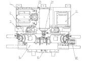
Fig. 1---the utility model front view.
Fig. 2---the utility model top view.
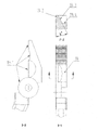
Fig. 3---the utility model left caliper structural representation, wherein, 3-1 is the left caliper front view, and 3-2 is the left caliper schematical top view, and 3-3 is the 3-1 cutaway view.
Fig. 4---the utility model right caliper body structural representation, wherein, 4-1 is the right caliper body front view, and 4-2 is the right caliper body schematical top view, and 4-3 is the 4-1 cutaway view.
Fig. 5---the left and right caliper forming surface of the utility model process schematic diagram, wherein, 5-1 is left and right caliper schematic diagram, and 5-2 is the forming surface schematic diagram, and 5-3 is left and right caliper processing rotation schematic diagram.
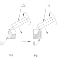
The outer cutting edge of Fig. 6---the utility model left caliper and right caliper body inner cutter hole, near coal-mine process schematic diagram, wherein, 6-1 is the outer cutting edge schematic diagram of left caliper, 6-2 is right caliper body inner cutter hole, near coal-mine schematic diagram.
The outer cutting edge of Fig. 7---the utility model right caliper body and left caliper inner cutter hole, near coal-mine process schematic diagram, wherein, 7-1 is the outer cutting edge schematic diagram of right caliper body, 7-2 left caliper inner cutter hole, near coal-mine schematic diagram.
In figure, each label represents:
left column 1, left vertical milling main spindle box 2, anticlockwise slide 3, left vertical shaft milling cutter 4, clamp body 5, workbench 6, cross slide seat 7, Y-direction servomotor 8, lathe bed 9, X-direction servomotor 10, right column 11, right rotation slide 12, right vertical milling main spindle box 13, right vertical shaft milling cutter 14, right vertical milling spindle motor 15, right vertical milling servomotor 16, lie on one's side and mill main spindle box 17, right caliper body 18, right caliper body forming surface 18-1, the outer cutting edge 18-2 of right caliper body, right caliper body inner cutter hole 18-3, the near coal-mine 18-4 of right caliper body, left caliper 19, left caliper forming surface 19-1, the outer cutting edge 19-2 of left caliper, left caliper inner cutter hole 19-3, the near coal-mine 19-4 of left caliper, lie on one's side and mill servomotor 20, left vertical milling servomotor 21, left vertical milling spindle motor 22, left column side rails 23, lie on one's side and mill forming cutter 24.
The specific embodiment
As Fig. 1, Fig. 2, Fig. 3, Fig. 4, Fig. 5, Fig. 6, shown in Figure 7:
Left vertical shaft milling cutter 4 connects with left vertical milling main spindle box 2 by left vertical milling main shaft (omit in figure, do not draw), and rotation on left vertical milling main spindle box 2; Left vertical milling main spindle box 2 (omits in figure by ball screw and nut, draw) with the guide rail of anticlockwise slide 3 on be flexibly connected, and driven by left vertical milling servomotor 21, and anticlockwise slide 3 is connected with left column 1 by bolt, there is setting angle a between anticlockwise slide 3 and left column 1, this setting angle a can adjust by rotation anticlockwise slide 3, and left column 1 is fixed on lathe bed 9.
Workbench 6 is actively coupled by the guide rail on ball screw and nut (omit in figure, draw) and cross slide seat 7, and is driven by X-direction servomotor 10, can do transverse movement; Cross slide seat 7 is actively coupled by the guide rail on ball screw and nut (omit in figure, draw) and lathe bed 9, and is driven by Y-direction servomotor 8, can do lengthwise movement.
Right vertical shaft milling cutter 14 is connected with right vertical milling main spindle box 13 by right vertical milling main shaft (omit in figure, do not draw), and rotation on right vertical milling main spindle box 13; Right vertical milling main spindle box 13 (omits in figure by ball screw and nut, draw) be connected with guide rail on right rotation slide 12, and driven by right vertical milling servomotor 16, and right rotation slide 12 is connected with right column 11 by bolt, there is setting angle b between right rotation slide 12 and right column 11, this setting angle b can adjust by rotation right rotation slide 12, and right column 11 is fixed on lathe bed 9.
Lie on one's side and mill forming cutter 24 and mill main shaft (omit in figure, draw) by lying on one's side and mill main spindle box 17 and connect with lying on one's side, and rotate lying on one's side to mill on main spindle box 17; Lie on one's side and mill main spindle box 17 and connects with left column 1 by ball screw and nut (omit in figure, draw), and mill servomotor 20 drivings by lying on one's side, move on left column side rails 23.
On clamp body 5 left and right two parts respectively the clamping workpiece to be machined be left caliper 19 and right caliper body 18, clamp body 5 is fixed on workbench 6.
Left vertical milling main spindle box 2, right vertical milling main spindle box 13 are symmetrically distributed in to lie on one's side and mill main spindle box 17 both sides; Anticlockwise slide 3 installed surfaces and left column side rails 23 are set on left column 1; Left vertical milling main spindle box 2, anticlockwise slide 3 connects, and is movably connected on anticlockwise slide 3 guide rails, lies on one's side to mill main spindle box 17 and connect with left column 1, and is movably connected on left column side rails 23.
Application process explanation of the present invention:
Be the angle of left caliper 19 and right caliper body 18 inner cutter holes, outer cutting edge according to processing work, adjust in advance anticlockwise slide 3, right rotation slide 12 setting angle a and the setting angle b on left column 1, right column 11.
Be left caliper 19 and right caliper body 18 clamping also clamping on clamp body 5 is left and right respectively with workpiece to be machined, before and after Y-direction servomotor 8 drives cross slide seat 7 works, (vertically) is mobile, it is mobile that workbench 6 drives work left and right (laterally) by X-direction servomotor 10, the milling position of main spindle box 17 is milled in fast feed to lying on one's side, mill lying on one's side on main spindle box 17 by lying on one's side and mill forming cutter 24 and complete successively left caliper forming surface 19-1 and right caliper body forming surface 18-1 milling; Mill completely, to the milling position of left vertical milling main spindle box 2, left vertical milling main spindle box 2 moves down workbench 6 with left caliper 19 rapid traverses on clamp body 5, and the outer cutting edge 19-2 of the first milling left caliper of left vertical shaft milling cutter 4 is to the position of setting; Mill complete, left vertical milling main spindle box 2 move up (main shaft does not stop), workbench 6 is with the milling position of right caliper body 18 rapid traverses on clamp body 5 to left vertical milling main spindle box 2, left vertical milling main spindle box 2 moves down fast, the suitable milling right caliper body inner cutter hole 18-3 again of left vertical shaft milling cutter 4 is to the position of setting, left vertical milling main spindle box 2 stops mobile (main shaft does not stop), and workbench 6 feeding of working left is by the left vertical shaft milling cutter 4 near coal-mine 18-4 of milling right caliper body; Mill completely, to the milling position of right vertical milling main spindle box 13, right vertical milling main spindle box 13 moves down workbench 6 with right caliper body 18 rapid traverses on clamp body 5, and the outer cutting edge 18-2 of the first milling right caliper body of right vertical shaft milling cutter 14 is to the position of setting; Mill complete, right vertical milling main spindle box 13 move up (main shaft does not stop), workbench 7 is with the milling position of left caliper 19 rapid traverses on clamp body 5 to right vertical milling main spindle box 13, right vertical milling main spindle box 13 moves down fast, right vertical shaft milling cutter 14 milling left caliper inner cutter hole 19-3 again arrives the position of setting, right vertical milling main spindle box 13 stops mobile (main shaft does not stop), and workbench 6 feeding of working to the right is by the right vertical shaft milling cutter 14 near coal-mine 19-4 of milling left caliper; Mill completely, workbench 6 falls back on the centre position left soon, and clamping workpiece enters next circulation.
During practical operation, the inner cutter hole that left vertical shaft milling cutter 4 also can first milling left caliper 19 and the outer cutting edge of the near coal-mine right caliper body of milling again 18, the inner cutter hole of the corresponding first milling right caliper body 18 of right vertical shaft milling cutter 14 and near coal-mine, the outer cutting edge of milling left caliper 19.
Analyzing of applying effects:
Three key elements that the present invention processes pliers: forming surface, outer cutting edge and inner cutter hole machine on a machine tool simultaneously by clamped one time, have guaranteed the machining accuracy of three key elements of pliers from technical equipment.
The outer cutting edge that the utility model adopts left vertical milling main spindle box can first mill out left caliper mills out the inner cutter hole of right caliper body and near coal-mine again, and the outer cutting edge that corresponding right vertical milling main spindle box mills out right caliper body mills out the inner cutter hole of left caliper and near coal-mine again; Left vertical shaft milling cutter also can first milling left caliper inner cutter hole and the near coal-mine outer cutting edge that mills out again right caliper body, the inner cutter hole of the corresponding first milling right caliper body of right vertical shaft milling cutter and near coal-mine, then mill out the outer cutting edge of left caliper.
When the utility model adopts left vertical milling main spindle box 2, right vertical milling main spindle box 13 milling inner cutter holes dexterously to desired location, stop mobile, then by workbench 6 respectively left, movement to the right, mill out near coal-mine; Like this, save a procedure and inner cutter hole and near coal-mine milling transitions smooth, the milling quality has the raising of matter.Drilling machine boring or milling machine hole milling are adopted near coal-mine processing usually to pliers compared to existing technology, have omitted this procedure.
The utility model with clamping workpiece after on fixture, complete forming surface, the inside and outside cutting edge of pliers and near coal-mine four road independent process Milling Process, whole process only needs people's operation, adopt compared to existing technology four lathes to divide four procedures, completed by four people's operations, efficiency significantly improves, and labour intensity obviously descends.
The utility model can satisfy the processing request of different inner cutter hole angle α ' and b ' easily by adjusting the adjustment of setting angle α and b on left column 1, right column 11 of anticlockwise slide 3, right rotation slide 12.The inner cutter hole angle is just fixing when jig Design compared to existing technology, change the inner cutter hole angle and must change fixture.
The utility model can be enhanced productivity two times compared to prior art, and the workpiece crudy has essence to improve.
The scope that the utility model is asked for protection is not limited to description of the present embodiment.
Claims (6)
1. multistation pliers CNC milling machine, is characterized in that left vertical shaft milling cutter connects with left vertical milling main spindle box by left vertical milling main shaft, and be rotationally connected with left vertical milling main spindle box; Left vertical milling main spindle box is connected with the anticlockwise slide by ball screw and nut, and is movably connected on the anticlockwise carriage rail, and the anticlockwise slide is connected with left column; Workbench is connected with cross slide seat by ball screw and nut, and is movably connected on the cross slide seat guide rail; Cross slide seat is connected with lathe bed by ball screw and nut, and is movably connected on bed ways; Right vertical shaft milling cutter is connected with right vertical milling main spindle box by right vertical milling main shaft, and is rotationally connected with right vertical milling main spindle box; Right vertical milling main spindle box is connected with the right rotation slide by ball screw and nut, and is movably connected on the right rotation carriage rail, and the right rotation slide is connected with right column; Lie on one's side and mill forming cutter and mill main shaft by lying on one's side and mill main spindle box and be connected with lying on one's side, and mill main spindle box and be rotationally connected with lying on one's side; Lie on one's side and mill main spindle box and be connected with left column, and be movably connected on the left column side rails.
2. multistation pliers CNC milling machine according to claim 1, is characterized in that the setting angle a of anticlockwise slide on left column is by the adjustment of anticlockwise slide.
3. multistation pliers CNC milling machine according to claim 1, is characterized in that the setting angle b of right rotation slide on right column is by the adjustment of right rotation slide.
4. multistation pliers CNC milling machine according to claim 1 is characterized in that left vertical milling main spindle box, right vertical milling main spindle box are symmetrically distributed in the sleeping main spindle box both sides of milling.
5. multistation pliers CNC milling machine according to claim 1, is characterized in that arranging on left column anticlockwise slide installed surface and left column side rails.
6. multistation pliers CNC milling machine according to claim 1 is characterized in that left vertical milling main spindle box anticlockwise slide connects, and is movably connected on the anticlockwise carriage rail, lies on one's side to mill main spindle box and connect with left column, and is movably connected on the left column side rails.
Priority Applications (1)
| Application Number | Priority Date | Filing Date | Title |
|---|---|---|---|
| CN 201220354701 CN203003229U (en) | 2012-07-17 | 2012-07-17 | Multi-station numerical control milling machine for pliers |
Applications Claiming Priority (1)
| Application Number | Priority Date | Filing Date | Title |
|---|---|---|---|
| CN 201220354701 CN203003229U (en) | 2012-07-17 | 2012-07-17 | Multi-station numerical control milling machine for pliers |
Publications (1)
| Publication Number | Publication Date |
|---|---|
| CN203003229U true CN203003229U (en) | 2013-06-19 |
Family
ID=48594862
Family Applications (1)
| Application Number | Title | Priority Date | Filing Date |
|---|---|---|---|
| CN 201220354701 Expired - Lifetime CN203003229U (en) | 2012-07-17 | 2012-07-17 | Multi-station numerical control milling machine for pliers |
Country Status (1)
| Country | Link |
|---|---|
| CN (1) | CN203003229U (en) |
Cited By (2)
| Publication number | Priority date | Publication date | Assignee | Title |
|---|---|---|---|---|
| CN102909415A (en) * | 2012-07-17 | 2013-02-06 | 南京宁庆数控机床制造有限公司 | Multi-station plier numerical control milling machine |
| CN103350350A (en) * | 2013-07-19 | 2013-10-16 | 张家港玉成精机有限公司 | Lateral vertical plate capable of adjusting center of gravity automatically |
-
2012
- 2012-07-17 CN CN 201220354701 patent/CN203003229U/en not_active Expired - Lifetime
Cited By (3)
| Publication number | Priority date | Publication date | Assignee | Title |
|---|---|---|---|---|
| CN102909415A (en) * | 2012-07-17 | 2013-02-06 | 南京宁庆数控机床制造有限公司 | Multi-station plier numerical control milling machine |
| CN103350350A (en) * | 2013-07-19 | 2013-10-16 | 张家港玉成精机有限公司 | Lateral vertical plate capable of adjusting center of gravity automatically |
| CN103350350B (en) * | 2013-07-19 | 2015-10-07 | 张家港玉成精机股份有限公司 | A kind of cant board of automatic adjustment center of gravity |
Similar Documents
| Publication | Publication Date | Title |
|---|---|---|
| CN202780719U (en) | Five-shaft numerically controlled engraving and milling machine | |
| CN202292095U (en) | Multi-station numerical control compound machine tool for adjustable wrenches | |
| CN102490012B (en) | Multi-station adjustable wrench numerical control combined machining machine tool | |
| CN102909415A (en) | Multi-station plier numerical control milling machine | |
| CN204912965U (en) | Horizontal lathe of screw thread hole is milled simultaneously at large -scale cylinder work piece both ends | |
| CN102699771A (en) | Horizontal type numerical control five axis drilling, milling and tapping special machine | |
| CN201815863U (en) | Boring, drilling and milling three-station combined machine tool | |
| CN102205437B (en) | Four-head four-station numerically controlled milling machine for clamp blade edge | |
| CN103042390A (en) | Six-shaft multi-stage numerical control drilling milling machine tool | |
| CN203304885U (en) | Multiple-workpiece processing device of drilling and tapping machine tool | |
| CN102001027A (en) | Four-axis four-linkage vertical machining centre | |
| CN102452004A (en) | Multifunctional intelligent vertical type numerical control machine tool | |
| CN201848699U (en) | Four-shaft four-connected moving vertical machining center | |
| CN103264281A (en) | Lathing, grinding, boring and milling integrated large-size composite horizontal type tool | |
| CN207139252U (en) | A kind of vertical end face milling & centering machine | |
| CN201579467U (en) | Gantry numerical control milling machine with rotational worktable | |
| CN205599958U (en) | Numerical control multistation multiaxis combination drilling machine | |
| CN205888539U (en) | Turnning and milling boring is attacked and is bored mill bed | |
| CN201913459U (en) | Intelligent multifunctional vertical numerical control machine tool | |
| CN203245400U (en) | Intelligent three-dimensional multiple-spindle single action and joint action adjustable numerical-control drilling and boring system | |
| CN202162413U (en) | Numerical control high-speed hole puncher | |
| CN203003229U (en) | Multi-station numerical control milling machine for pliers | |
| CN203141235U (en) | Inclined lathe bed turning center | |
| CN202207822U (en) | Four-head four-station pincer cutting edge numerical control milling machine | |
| CN202428008U (en) | Numeric control milling machine for spindle excircle raceways |
Legal Events
| Date | Code | Title | Description |
|---|---|---|---|
| C14 | Grant of patent or utility model | ||
| GR01 | Patent grant | ||
| CX01 | Expiry of patent term |
Granted publication date: 20130619 |
|
| CX01 | Expiry of patent term |