CN202975222U - Integrated tester for secondary circuit of current transformer - Google Patents
Integrated tester for secondary circuit of current transformer Download PDFInfo
- Publication number
- CN202975222U CN202975222U CN 201220636719 CN201220636719U CN202975222U CN 202975222 U CN202975222 U CN 202975222U CN 201220636719 CN201220636719 CN 201220636719 CN 201220636719 U CN201220636719 U CN 201220636719U CN 202975222 U CN202975222 U CN 202975222U
- Authority
- CN
- China
- Prior art keywords
- current
- ammeter
- test
- current transformer
- circuit
- Prior art date
- Legal status (The legal status is an assumption and is not a legal conclusion. Google has not performed a legal analysis and makes no representation as to the accuracy of the status listed.)
- Expired - Fee Related
Links
- 238000012360 testing method Methods 0.000 claims abstract description 64
- 238000004804 winding Methods 0.000 claims description 7
- 230000001681 protective effect Effects 0.000 description 4
- 238000010586 diagram Methods 0.000 description 2
- 238000012423 maintenance Methods 0.000 description 2
- 230000015572 biosynthetic process Effects 0.000 description 1
- 230000007812 deficiency Effects 0.000 description 1
- 238000005516 engineering process Methods 0.000 description 1
- 238000005259 measurement Methods 0.000 description 1
- 238000000819 phase cycle Methods 0.000 description 1
- 238000010998 test method Methods 0.000 description 1
Images
Landscapes
- Testing Electric Properties And Detecting Electric Faults (AREA)
Abstract
The utility model discloses an integrated tester for a secondary circuit of a current transformer, belonging to the technical field of testing. The technical scheme is that, the tester comprises a battery pack, a current passage test circuit and a point polarity test circuit, wherein the current passage test circuit comprises an inverter, an alternating-current ammeter, a current passage test switch and a current-limiting resistor, a direct-current input terminal of the inverter is connected to the battery pack through the current passage test switch, and an alternating current output on an alternating side of the inverter is fed into the secondary circuit of the current transformer to be tested via the alternating-current ammeter and the current-limiting resistor. The integrated tester provided by the utility model has the advantages of complete functions, simple operation, light weight and convenience in carrying and management, providing great reduction in labor intensity of the test personnel and improvement in working efficiency of the current transformer test.
Description
Technical field
The utility model relates to a kind of device for current transformer being carried out point-polarity test and secondary circuit through-flow test, belongs to technical field of measurement and test.
Background technology
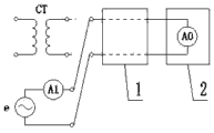
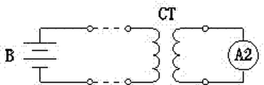
The secondary loop of mutual inductor through-flow test is to utilize additional power source to pass into the electric current (referring to Fig. 1) of setting in the secondary circuit of current transformer; then relatively whether the electric current that collects of protective device is consistent with the electric current that passes into; and whether correct with this secondary circuit wiring of verifying mutual inductor, namely whether there are open circuit, shunting or phase sequence mistake in Fig. 1 in terminal box 1.The point-polarity test is to utilize battery to pass in short-term DC current (referring to Fig. 2) in winding of current transformer, observes simultaneously the deflection situation of the ammeter pointer in secondary circuit, judges the polarity of Secondary Winding with this.Although above two kinds of tests are usually carried out at one time, present two kinds of test units of adopting of test are independent of each other, have so just increased the kind of test apparatus, to instrument carry, deposit and management is made troubles.
At present; the instrument that the secondary loop of mutual inductor through-flow test adopts is the reaying protection test instrument; although this instrument measuring accuracy high (considerably beyond the accuracy requirement of general through-flow test); but its weight too large (40Kg nearly) and need to connect the maintenance power supply; greatly increase the labour intensity of testing crew, reduced the work efficiency of through-flow test.In addition, existing point-polarity test method only accesses reometer in the secondary circuit of current transformer, when causing not deflection of ammeter pointer due to line fault, testing crew is difficult to primary circuit or the secondary circuit that failure judgement occurs in current transformer, is unfavorable for the quick eliminating of fault.
Summary of the invention
The purpose of this utility model is to overcome the deficiencies in the prior art, a kind of portable type current transformer secondary circuit comprehensive test apparatus is provided, and to reduce the labour intensity of testing crew, improves the work efficiency of current transformer test.
The purpose of this utility model realizes with following technical proposals:
A kind of secondary loop of mutual inductor comprehensive test apparatus, formation comprises electric battery, through-flow test circuit and point-polarity hookup, described through-flow test circuit comprises inverter, alternating current ammeter, through-flow test switch and current-limiting resistance, the direct-flow input end of described inverter connects electric battery through the through-flow test switch, and the alternating current of its AC output injects the secondary circuit of tested current transformer through alternating current ammeter and current-limiting resistance.
Above-mentioned secondary loop of mutual inductor comprehensive test apparatus, described point-polarity hookup comprises primary side DC ammeter, point-polarity test switch and secondary side DC ammeter, the primary side DC ammeter is connected in series with a winding of tested current transformer the output voltage that connects electric battery by the point-polarity test switch, and the two ends of secondary side DC ammeter are connected with the two ends of the Secondary Winding of tested current transformer respectively.
The utility model integrates through-flow test circuit and point-polarity hookup, and two hookups have not only reduced the kind of current transformer test apparatus by battery-powered, and greatly reduces the weight of test apparatus.In addition, this test instrument does not need to connect the maintenance power supply, has simplified test operation, has saved test period.Two reometers are set in the point-polarity hookup, are conducive to testing crew fast finding line fault.
The utility model is multiple functional, simple to operate, lightweight, is easy to carry and manages, and can greatly reduce the labour intensity of testing crew, improves the work efficiency of current transformer test.
Description of drawings
The utility model is described in further detail below in conjunction with accompanying drawing.
Fig. 1 is secondary loop of mutual inductor through-flow test schematic diagram;
Fig. 2 is point-polarity test principle figure;
Fig. 3 is electrical schematic diagram of the present utility model.
In figure, each label is: 1, terminal box; 2, protective device; CT, current transformer; DC/AC, inverter; E, AC power; B, electric battery; Reometer in A0, protective device; A1, alternating current ammeter; A2, secondary side DC ammeter; A3, primary side DC ammeter; R, current-limiting resistance; K1, through-flow test switch; K2, point-polarity test switch.
Embodiment
Referring to Fig. 3, the utility model is comprised of electric battery B, inverter DC/AC, alternating current ammeter A1, primary side DC ammeter A3, secondary side DC ammeter A2 and current-limiting resistance R.Inverter DC/AC, alternating current ammeter A1 and current-limiting resistance R consist of the through-flow test circuit, and primary side DC ammeter A3 and secondary side DC ammeter A2 consist of the point-polarity hookup.Two hookups all adopt electric battery B power supply.
The alternating voltage of inverter DC/AC output 10V, the resistance of current-limiting resistance R is 10 ohm, so just with current limit about 1A.When carrying out through-flow test, tested Current Transmit and terminal box 1 are disconnected; the through-flow test circuit is connected (the through-flow test circuit is serially connected in the secondary circuit of Current Transmit) with current transformer connection post in terminal box 1; closed through-flow test K switch 1; relatively the reometer A0 in protective device and the measured value of alternating current ammeter A1, just can complete through-flow work.
When carrying out the point-polarity test, by Fig. 3, secondary side DC ammeter A2, primary side DC ammeter A3, point-polarity test switch K2 and tested Current Transmit are connected, closing point polarity test K switch 2, judge Secondary Winding polarity by the needle deflection direction of observing secondary side DC ammeter A2 in short-term.If the not deflection of pointer of secondary side DC ammeter A2, and the needle deflection of primary side DC ammeter A3 illustrates that there is open circuit fault in secondary circuit.If the not deflection of pointer of primary side DC ammeter A3 illustrates that fault is in the primary circuit of current transformer.
Claims (2)
1. secondary loop of mutual inductor comprehensive test apparatus, it is characterized in that, it comprises electric battery (B), through-flow test circuit and point-polarity hookup, described through-flow test circuit comprises inverter (DC/AC), alternating current ammeter (A1), through-flow test switch (K1) and current-limiting resistance (R), the direct-flow input end of described inverter (DC/AC) connects electric battery (B) through through-flow test switch (K1), and the alternating current of its AC output injects the secondary circuit of tested current transformer through alternating current ammeter (A1) and current-limiting resistance (R).
2. secondary loop of mutual inductor comprehensive test apparatus according to claim 1, it is characterized in that, described point-polarity hookup comprises primary side DC ammeter (A3), point-polarity test switch (K2) and secondary side DC ammeter (A2), primary side DC ammeter (A3) is connected in series with a winding of tested current transformer (CT) output voltage that meets electric battery (B) by point-polarity test switch (K2), and the two ends of secondary side DC ammeter (A2) are connected with the two ends of the Secondary Winding of tested current transformer (CT) respectively.
Priority Applications (1)
| Application Number | Priority Date | Filing Date | Title |
|---|---|---|---|
| CN 201220636719 CN202975222U (en) | 2012-11-28 | 2012-11-28 | Integrated tester for secondary circuit of current transformer |
Applications Claiming Priority (1)
| Application Number | Priority Date | Filing Date | Title |
|---|---|---|---|
| CN 201220636719 CN202975222U (en) | 2012-11-28 | 2012-11-28 | Integrated tester for secondary circuit of current transformer |
Publications (1)
| Publication Number | Publication Date |
|---|---|
| CN202975222U true CN202975222U (en) | 2013-06-05 |
Family
ID=48516280
Family Applications (1)
| Application Number | Title | Priority Date | Filing Date |
|---|---|---|---|
| CN 201220636719 Expired - Fee Related CN202975222U (en) | 2012-11-28 | 2012-11-28 | Integrated tester for secondary circuit of current transformer |
Country Status (1)
| Country | Link |
|---|---|
| CN (1) | CN202975222U (en) |
Cited By (5)
| Publication number | Priority date | Publication date | Assignee | Title |
|---|---|---|---|---|
| CN103605001A (en) * | 2013-12-06 | 2014-02-26 | 国家电网公司 | Charged-state current secondary circuit test coupling device |
| CN104749480A (en) * | 2015-03-08 | 2015-07-01 | 国家电网公司 | Whole-set secondary circuit polarity testing device used for relay protection |
| CN107037307A (en) * | 2017-03-30 | 2017-08-11 | 西安热工研究院有限公司 | A kind of secondary through-flow method of power plant main system c-type |
| CN112415460A (en) * | 2020-09-07 | 2021-02-26 | 青岛鼎信通讯股份有限公司 | Current transformer fault self-diagnosis system and method |
| CN113109754A (en) * | 2021-04-08 | 2021-07-13 | 国网宁夏电力有限公司 | Method for detecting integrity of primary and secondary loops of current transformer |
-
2012
- 2012-11-28 CN CN 201220636719 patent/CN202975222U/en not_active Expired - Fee Related
Cited By (7)
| Publication number | Priority date | Publication date | Assignee | Title |
|---|---|---|---|---|
| CN103605001A (en) * | 2013-12-06 | 2014-02-26 | 国家电网公司 | Charged-state current secondary circuit test coupling device |
| CN104749480A (en) * | 2015-03-08 | 2015-07-01 | 国家电网公司 | Whole-set secondary circuit polarity testing device used for relay protection |
| CN104749480B (en) * | 2015-03-08 | 2017-06-30 | 国网山东省电力公司枣庄供电公司 | One kind is used for relay protection secondary circuit whole group polarity test device |
| CN107037307A (en) * | 2017-03-30 | 2017-08-11 | 西安热工研究院有限公司 | A kind of secondary through-flow method of power plant main system c-type |
| CN107037307B (en) * | 2017-03-30 | 2019-06-04 | 西安热工研究院有限公司 | A kind of secondary through-flow method of power plant main system c-type |
| CN112415460A (en) * | 2020-09-07 | 2021-02-26 | 青岛鼎信通讯股份有限公司 | Current transformer fault self-diagnosis system and method |
| CN113109754A (en) * | 2021-04-08 | 2021-07-13 | 国网宁夏电力有限公司 | Method for detecting integrity of primary and secondary loops of current transformer |
Similar Documents
| Publication | Publication Date | Title |
|---|---|---|
| CN103454554B (en) | Polarity tester for current transformer | |
| CN202975222U (en) | Integrated tester for secondary circuit of current transformer | |
| CN203502540U (en) | Current transformer polarity tester | |
| CN203838286U (en) | Current transformer polarity tester | |
| CN201628747U (en) | On-line detection device for insulation resistance of suspension insulator | |
| CN204925293U (en) | Power line error detection device | |
| CN105487039A (en) | Conjunction box without power loss during replacement | |
| CN207730852U (en) | A kind of charging pile detecting system of electric vehicle | |
| CN103777077B (en) | Wireless pincerlike phase detection device | |
| CN109212357A (en) | A kind of portable SVG power module test tooling | |
| CN201749136U (en) | In-situ quick checking, analyzing and judging device with electricity stealing prevention | |
| CN107677915A (en) | Use mutual inductor polarity measurement apparatus and its measuring method in Portable metering scene | |
| CN207440181U (en) | A kind of dynamic resistance of high-voltage circuit breaker measuring system | |
| CN209055613U (en) | A kind of earth detector suitable for different form stringing | |
| CN201130227Y (en) | Portable DC earthing seeking instrument | |
| CN202421409U (en) | Portable polarity tester for mutual inductors | |
| CN202815146U (en) | Polarity detector for mutual inductor | |
| CN105891664A (en) | Multi-path analog loop and polarity calibration instrument | |
| CN204832408U (en) | Portable current transformer secondary circuit tester of working a telephone switchboard | |
| CN209432939U (en) | A kind of high-power transformer second protection polarity test device | |
| CN204832412U (en) | Novel combined instrument transformer polarity test appearance | |
| CN206892308U (en) | A kind of novel power supply screen monitors single-board testing platform | |
| CN102121976A (en) | Portable polarity calibration device for mutual inductor | |
| CN202421408U (en) | Current transformer polarity test device | |
| CN211826149U (en) | Test platform for train equipment power supply device |
Legal Events
| Date | Code | Title | Description |
|---|---|---|---|
| C14 | Grant of patent or utility model | ||
| GR01 | Patent grant | ||
| CF01 | Termination of patent right due to non-payment of annual fee | ||
| CF01 | Termination of patent right due to non-payment of annual fee |
Granted publication date: 20130605 Termination date: 20171128 |