CN202953783U - Special device for installing air hose - Google Patents
Special device for installing air hose Download PDFInfo
- Publication number
- CN202953783U CN202953783U CN 201220669411 CN201220669411U CN202953783U CN 202953783 U CN202953783 U CN 202953783U CN 201220669411 CN201220669411 CN 201220669411 CN 201220669411 U CN201220669411 U CN 201220669411U CN 202953783 U CN202953783 U CN 202953783U
- Authority
- CN
- China
- Prior art keywords
- airduct
- expansion bracket
- base
- saddle
- special purpose
- Prior art date
- Legal status (The legal status is an assumption and is not a legal conclusion. Google has not performed a legal analysis and makes no representation as to the accuracy of the status listed.)
- Expired - Fee Related
Links
Images
Abstract
The utility model discloses a special device for installing an air hose. The special device comprises two elevators with the same specification, wherein each elevator comprises a base, an expansion bracket and a plunger-type cylinder, wherein the expansion bracket is movably connected to the base, the plunger-type cylinder is arranged on the base, the upper end of the plunger-type cylinder is connected with a connecting pin of the expansion bracket, a support platform is fixed on the top of the expansion bracket, the two sides of the support platform are fixedly connected with baffle plates, and a micro-adjustment device is arranged on the upper surface of the support platform. The special device has no damage to the air hose self and civil engineering structure, has high safety, can be successfully mounted by a few installation personnel and greatly improves the construction efficiency.
Description
Technical field
The utility model relates to the ventilation system engineering, is specifically related to a kind of special purpose device that airduct is installed.
Background technology
Airduct is exactly the plumbing system of carrying and distributing for air.The installation of airduct at present adopts the mode of lifting usually, at first will load onto hoisting ring in the two ends of airduct, then chain sling is hung on hoisting ring, and every termination holds up airduct with a cross-arm, finally airduct is sling.The method also has destructive effect to civil engineering structure; if secondly in lifting process, exert oneself the inhomogeneous meeting destruction certain to the structure generation of airduct; and the phenomenon that airduct breaks away from often can occur; adopting lifting that airduct is installed needs more hoisting personnel to be operated, and the level of operating personal is had relatively high expectations.Therefore current airduct is installed because do not have special purpose device to cause inefficiency, and danger coefficient is large.
Summary of the invention
The utility model technical issues that need to address are to provide a kind of special purpose device that airduct is installed, and easy and simple to handle, safety performance is high, have greatly improved work efficiency.
The utility model is achieved through the following technical solutions:
A kind of special purpose device that airduct is installed, comprise two elevators that specification is identical, and described elevator comprises base, is movably connected on the expansion bracket on base, and be arranged at the plunger case on base, and the upper end of described plunger case is connected with the connecting pin of expansion bracket; The expansion bracket top of described elevator is fixed with saddle, and the both sides of described saddle are fixedly connected with baffle plate, and described saddle upper surface is provided with micromatic setting.
The further improvement project of the utility model is, described micromatic setting is the some cylinders that are parallel to described baffle plate, the latter half of described cylinder sinks in the circular groove that described saddle upper surface is provided with, and the anchor shaft of described cylinder is fixed on the two ends in arc groove.
The utility model further improvement project is that described baffle plate 3 is connected with saddle 2 use bolts.
The utility model further improvement project is that the base of described elevator has road wheel.
The utility model further improvement project is that described elevator is provided with overload protective device.
The utility model further improvement project is that the circuit of the lifting power plant of two elevators is parallel to same control unit.
The utility model compared with prior art has the following advantages:
One, application of the present utility model; can not damage airduct itself and civil engineering structure; between two saddles, cross-arm is installed during installation; airduct can complete assembling on cross-arm; when airduct is delivered to assigned address, this cross-arm is connected with preassembled airduct suspension rod, in the process of lifting, airduct has baffle plate and cross-arm protection; also be provided with overload protective device on elevator, improved and installed whole safety performance.
Two, the utility model is flexible for installation, can the mobile lift adjustment when installation position is equipped with relatively large deviation, and minor deviations can be regulated by the cylinder on saddle.
Three, the utility model is simple to operate, and the circuit of the lifting power plant of two elevators is parallel to same control unit, and few installation personnel just can complete installation, has greatly improved operating efficiency.
The accompanying drawing explanation
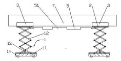
Fig. 1 is that the utility model master looks schematic diagram.
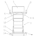
Fig. 2 is the utility model schematic side view.
The specific embodiment
As shown in Figure 1, 2, a kind of special purpose device that airduct is installed, comprise two elevators 1 that specification is identical, described elevator 1 comprises base 11, be movably connected on the expansion bracket 12 on base, and being arranged at the plunger case 13 on base 11, the upper end of described plunger case 13 is connected with the connecting pin of expansion bracket 12; The base 7 of elevator 1 also is provided with road wheel, and the circuit that machine 1 is provided with the lifting power plant of two elevators 1 of overload protective device is parallel to same control unit.Operating personal only need just can complete the control to two elevators 1 by a controller.Expansion bracket 12 tops of elevator 1 are fixed with saddle 2, and the both sides of described saddle 2 are fixedly connected with baffle plate 3.When airduct 7 is installed; the cross-arm of airduct 75 two ends are carried on a shoulder pole between the saddle 2 of two elevators 1; baffle plate 3 is connected with saddle 2 use bolts, takes bolt apart and puts down baffle plate, allows the assembly of airduct 7 be assembled on cross-arm; after installation; load onto baffle plate 3, whole airduct 7 is held up by saddle 2, under the control of elevator 1; airduct 7 is delivered to installation site, and now baffle plate 3,5 pairs of airducts 7 of cross-arm play a protective role.Elevator 1 is provided with overload protective device in addition, when airduct is overweight, can report to the police, and has improved the safety in whole work progress.
Still as shown in Figure 1, 2, the micromatic setting 4 of described saddle 2 upper surfaces is two cylinders 6 that are parallel to baffle plate 3, and the latter half of cylinder 6 sinks in the circular groove that saddle 2 upper surfaces are provided with, and the anchor shaft of cylinder 6 is fixed on the two ends in arc groove.After airduct 7 is delivered to setting height(from bottom), elevator 1 can not be realized the displacement adjusting that level attitude is trickle, now promote the main body of airduct 7, effect lower air conduit 7 at roller 6 can complete fine adjustments in the horizontal direction, and after adjusting position, the bottom surface of cross-arm 5 is provided with the cross-arm that is permanently fixed that groove 51 is placed airduct 7, cross-arm 5 is connected with preassembled airduct suspension rod, finally fix airduct 7, fall the expansion bracket 12 of elevator 1, complete installation.
Claims (6)
1. the special purpose device that airduct is installed, comprise two elevators (1) that specification is identical, it is characterized in that: described elevator (1) comprises base (11), be movably connected on the expansion bracket (12) on base, and being arranged at the plunger case (13) on base (11), the upper end of described plunger case (13) is connected with the connecting pin of expansion bracket (12); Expansion bracket (12) top of described elevator (1) is fixed with saddle (2), and the both sides of described saddle (2) are fixedly connected with baffle plate (3), and described saddle (2) upper surface is provided with micromatic setting (4).
2. a kind of special purpose device that airduct is installed as claimed in claim 1, it is characterized in that: described micromatic setting (4) is for being parallel to some cylinders (6) of described baffle plate (3), the latter half of described cylinder (6) sinks in the circular groove that described saddle (2) upper surface is provided with, and the anchor shaft of described cylinder (6) is fixed on the two ends in arc groove.
3. a kind of special purpose device that airduct is installed as claimed in claim 1, it is characterized in that: described baffle plate (3) is connected with bolt with saddle (2).
4. a kind of special purpose device that airduct is installed as claimed in claim 1, it is characterized in that: the base (11) of described elevator (1) has road wheel (14).
5. a kind of special purpose device that airduct is installed as claimed in claim 1, it is characterized in that: described elevator (1) is provided with overload protective device.
6. a kind of special purpose device that airduct is installed as claimed in claim 1, it is characterized in that: the circuit of the lifting power plant of two elevators (1) is parallel to same control unit.
Priority Applications (1)
| Application Number | Priority Date | Filing Date | Title |
|---|---|---|---|
| CN 201220669411 CN202953783U (en) | 2012-12-07 | 2012-12-07 | Special device for installing air hose |
Applications Claiming Priority (1)
| Application Number | Priority Date | Filing Date | Title |
|---|---|---|---|
| CN 201220669411 CN202953783U (en) | 2012-12-07 | 2012-12-07 | Special device for installing air hose |
Publications (1)
| Publication Number | Publication Date |
|---|---|
| CN202953783U true CN202953783U (en) | 2013-05-29 |
Family
ID=48459365
Family Applications (1)
| Application Number | Title | Priority Date | Filing Date |
|---|---|---|---|
| CN 201220669411 Expired - Fee Related CN202953783U (en) | 2012-12-07 | 2012-12-07 | Special device for installing air hose |
Country Status (1)
| Country | Link |
|---|---|
| CN (1) | CN202953783U (en) |
Cited By (1)
| Publication number | Priority date | Publication date | Assignee | Title |
|---|---|---|---|---|
| CN102996897A (en) * | 2012-12-07 | 2013-03-27 | 中铁十九局集团电务工程有限公司 | Special device for installing air hose |
-
2012
- 2012-12-07 CN CN 201220669411 patent/CN202953783U/en not_active Expired - Fee Related
Cited By (1)
| Publication number | Priority date | Publication date | Assignee | Title |
|---|---|---|---|---|
| CN102996897A (en) * | 2012-12-07 | 2013-03-27 | 中铁十九局集团电务工程有限公司 | Special device for installing air hose |
Similar Documents
| Publication | Publication Date | Title |
|---|---|---|
| CN204030347U (en) | A kind of ring main unit integration is from bogey | |
| CN102383748A (en) | Novel injection head turning device | |
| CN104477788A (en) | Spanning self-climbing type translational crane of wind power generation tower | |
| CN102996897A (en) | Special device for installing air hose | |
| CN103953200B (en) | Wallboard mounting machine | |
| CN206827835U (en) | A kind of combination unit for power transmission and transformation installation | |
| CN204858400U (en) | Slope shaft tower unscrambler | |
| CN203031575U (en) | Hydroelectric power plant guide vane servomotor push-pull rod overhaul bearing tackle | |
| CN201756399U (en) | Lifting device | |
| CN202564866U (en) | Supporting frame used for high-voltage cable pothead manufacture | |
| CN202953783U (en) | Special device for installing air hose | |
| CN203846787U (en) | Wallboard assembling machine | |
| CN105016220A (en) | Holding rod joint adding device | |
| CN202214125U (en) | Crane girder combined hoisting device with auxiliary truss | |
| CN203438155U (en) | Saddle seat for installing and supporting large-sized ball mill barrel | |
| CN203767849U (en) | Lifting tool for disassembling stainless steel leveling machine servo oil cylinder | |
| CN204752009U (en) | Maintenance is with having rotated gallows | |
| CN210013125U (en) | Stretch-draw regularization operation platform | |
| CN203319620U (en) | Portable jack | |
| CN109194046B (en) | Special combined tool for taking out motor rotor | |
| CN203361596U (en) | Auxiliary support of integrated lifting operation platform | |
| CN206267536U (en) | A kind of steel column material distributing machine | |
| CN105506204A (en) | Disassembly and assembly mechanical hand for blast furnace air hose maintenance | |
| CN203571222U (en) | Ladder-type cable bridge | |
| CN203441093U (en) | Portal lifting device for building construction |
Legal Events
| Date | Code | Title | Description |
|---|---|---|---|
| C14 | Grant of patent or utility model | ||
| GR01 | Patent grant | ||
| CF01 | Termination of patent right due to non-payment of annual fee |
Granted publication date: 20130529 Termination date: 20201207 |
|
| CF01 | Termination of patent right due to non-payment of annual fee |